

ProductPRODUCT
Featured products
Contact Us
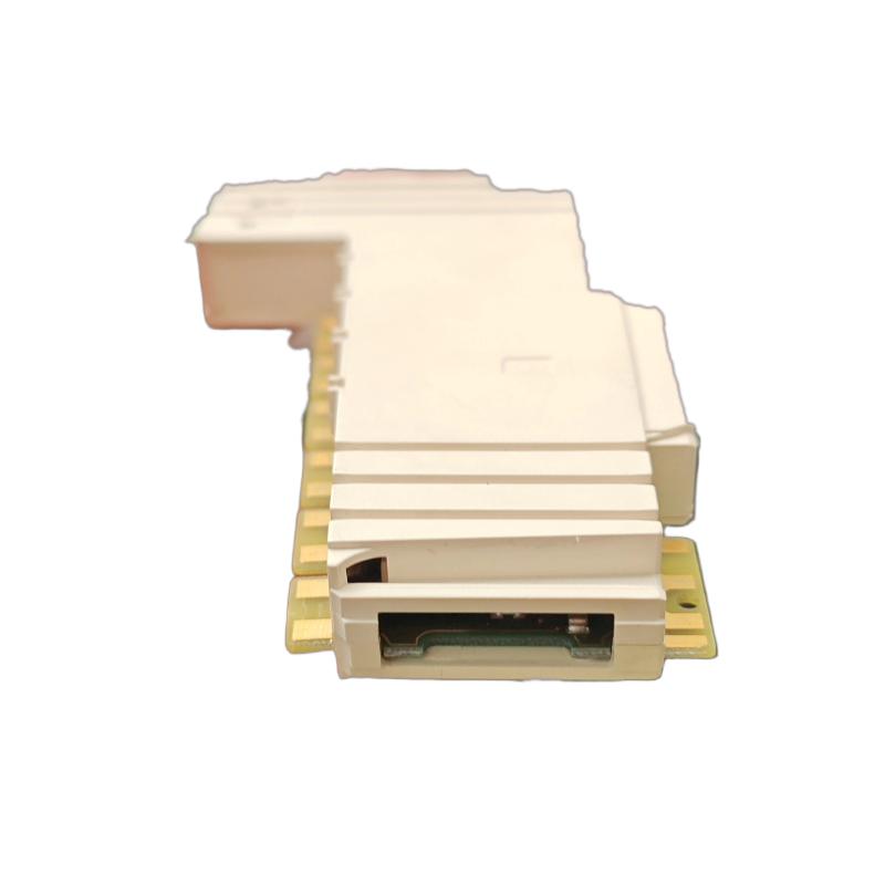
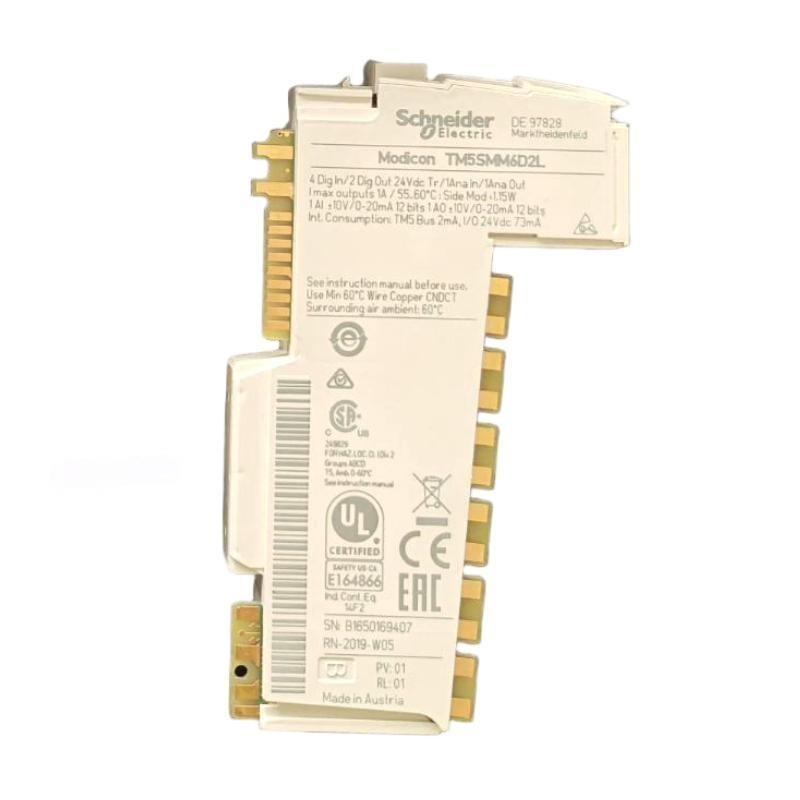
- Schneider
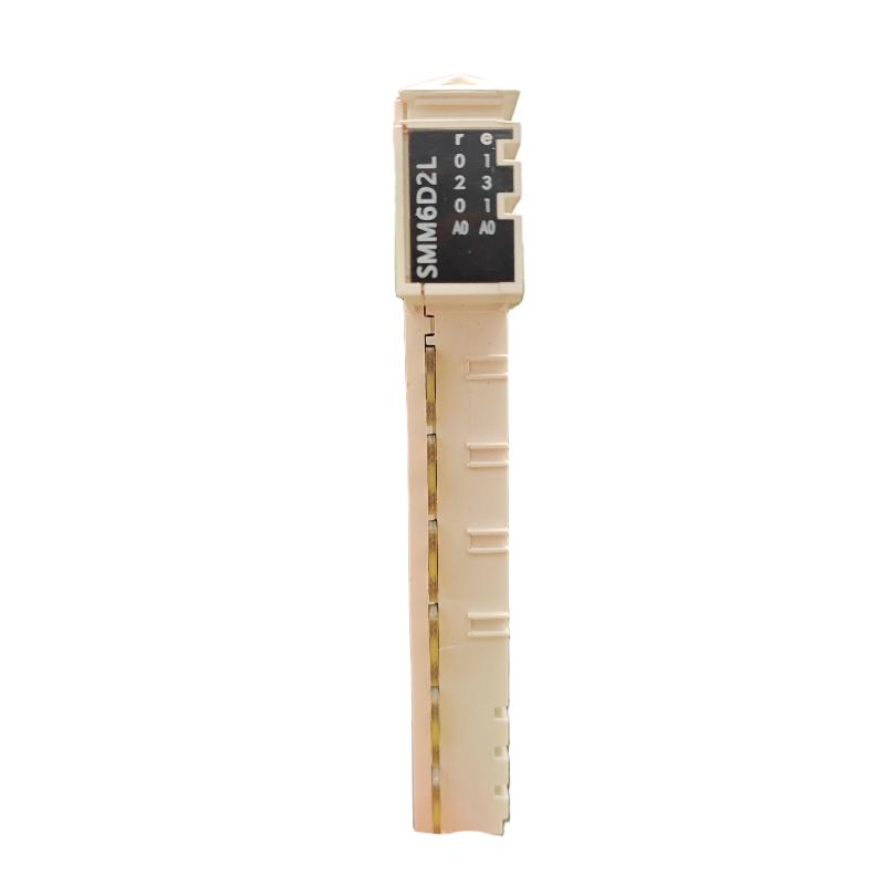
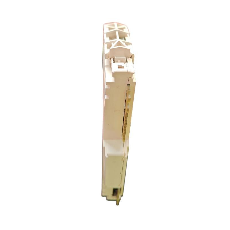
- TM5SMM6D2L
- Analog Hybrid I/O Module
- France
- 99 × 12.5 × 75 mm
- 0.025 kg
- Xiamen, China
- New & In Stock
- T/T, PayPal, Western Union
- 1 Year
- 1-3 Working Days
- DHL, UPS, TNT, FedEx and EMS.
- 24-Hour Service
- COO
- 3
Our advantage

Global Logistics
We have a 10-year logistics and express cooperation agreement, so our products can be shipped to any place in the world.

Brand new and original
Our products are imported in bulk from the place of origin. Because of the cooperative relationship, our products are all original and 100% new.

24-hour service
We provide 7*24 hours service to our customers. We will be there whenever you need us.

Price advantage
All our products are priced very favorably because we have our own warehouse and supply.
| Company Information | |||
| [email protected] | |||
| Mobile | +8615980777398 | ||
| +8615980777398 | |||
| 15980777398 |
1. Product Overview
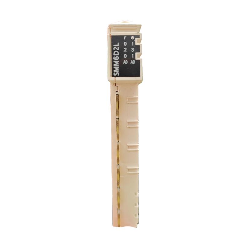
The Schneider Electric TM5SMM6D2L Analog Hybrid I/O Module is a mixed input/output module in the Modicon TM5 modular automation system. It combines digital and analog signal processing in one compact unit, helping machine builders integrate multiple field devices while reducing the number of separate I/O modules required.
The module provides four digital inputs, two digital transistor outputs, one analog input, and one analog output. The analog input supports voltage and current signals, while the analog output supports voltage and current control signals within the module’s specified ranges. This combination makes the TM5SMM6D2L suitable for industrial machines that require both discrete status monitoring and continuous process control.
Typical applications include packaging machinery, material handling systems, automated assembly equipment, production lines, and general machine-control systems. Digital inputs can monitor switches and sensor states, digital outputs can command compatible actuators, analog inputs can acquire process measurements, and analog outputs can provide reference signals to compatible control devices.
With dimensions of 99 × 12.5 × 75 mm and a weight of 0.025 kg, the module is designed for compact installation within a compatible Modicon TM5 I/O assembly.
2. Technical Specifications
| Parameter | Specification |
|---|---|
| Brand | Schneider Electric |
| Model Number | TM5SMM6D2L |
| Product Type | Analog Hybrid I/O Module |
| Product Range | Modicon TM5 |
| Digital Inputs | 4 |
| Digital Input Voltage | 24 V DC |
| Digital Input Current | 3.3 mA per input |
| Digital Outputs | 2 |
| Digital Output Type | Transistor |
| Digital Output Voltage | 24 V DC |
| Digital Output Current | Up to 0.5 A per output |
| Analog Inputs | 1 |
| Analog Input Signal | ±10 V DC or 0–20 mA / 4–20 mA |
| Analog Outputs | 1 |
| Analog Output Signal | ±10 V DC or 0–20 mA |
| Analog Input Resolution | 12 bits + sign for voltage; 12 bits for current |
| Analog Output Resolution | 12 bits + sign for voltage; 12 bits for current |
| Nominal Supply Voltage | 24 V DC |
| Supply Voltage Range | 20.4–28.8 V DC |
| Compatible Controller Families | Modicon M258 and LMC058, subject to system configuration |
| Compatible Bus Base | TM5ACBM11 or TM5ACBM15 |
| Compatible Terminal Block | TM5ACTB12 |
| Dimensions | 99 × 12.5 × 75 mm |
| Weight | 0.025 kg |
| Typical Applications | Machine control, packaging, assembly, material handling |
The specifications listed above describe the module’s principal I/O characteristics. Actual performance and compatibility depend on the system configuration, field wiring, engineering software, and installation conditions.
3. Function and Working Principle
The TM5SMM6D2L combines digital input, digital output, analog input, and analog output functions in a single electronic module. Each channel type performs a different role in the control system.
3.1 Digital Input Processing
The four digital inputs accept compatible 24 V DC signals from field devices such as proximity sensors, photoelectric sensors, limit switches, and push buttons.
When an input signal reaches the appropriate switching threshold, the module registers its state and makes the corresponding digital value available to the controller. The controller program can use these signals to initiate machine sequences, confirm operating conditions, detect component positions, or respond to operator commands.
Correct input wiring and suitable signal filtering are important for reliable detection, especially in applications with electrical interference or mechanical contact bounce.
3.2 Digital Output Control
The two digital outputs use transistor switching to control compatible 24 V DC loads. Depending on the application, these outputs may operate indicator devices, interface relays, solenoid valves, or other suitable actuators.
The maximum rated output current is 0.5 A per channel. The connected load must remain within the module’s electrical limits, including any applicable common-current and transient constraints.
Loads that exceed the module’s ratings should not be connected directly. Where necessary, use a properly rated external interface device.
3.3 Analog Input Acquisition
The analog input receives a voltage or current signal from a compatible transmitter or measuring device. Supported input ranges include:
- Voltage: −10 to +10 V DC
- Current: 0–20 mA
- Current: 4–20 mA
The module converts the input signal into a digital value that can be processed by the controller. The controller program can then scale the value into an engineering unit, such as temperature, pressure, speed, position, or flow, depending on the connected instrument.
The configured signal type must match the physical wiring. An incorrect voltage/current configuration can damage the module, so the channel configuration and field connection must be checked before power is applied.
3.4 Analog Output Generation
The analog output provides a continuous control signal for a compatible external device. It supports a voltage range of −10 to +10 V DC or a current range of 0–20 mA, according to the selected configuration.
For example, a controller may calculate a speed reference and send it through the analog output to a compatible drive. Other applications may use the output to provide a setpoint to a process controller or other analog-controlled equipment.
The receiving device’s input type and electrical requirements must match the output configuration.
3.5 Controller Communication
The module operates as part of the Modicon TM5 I/O system. The controller exchanges I/O data with the module through the system bus, allowing digital states and analog values to be incorporated into the control program.
In the engineering software, the I/O mapping configuration associates module channels with program variables. Correct mapping and scaling are essential to ensure that the controller interprets the signals as intended.
4. Role in Industrial Automation Systems
Compact Mixed-Signal Integration
Combining four digital inputs, two digital outputs, one analog input, and one analog output enables the TM5SMM6D2L to support applications that require several types of field signals in a limited installation space.
Process Monitoring
The analog input can acquire measurements from compatible transmitters, while digital inputs monitor machine states and discrete sensor signals. Together, these signals give the controller information about both process conditions and equipment status.
Actuator Control
The digital outputs can command compatible 24 V DC devices, while the analog output can provide a variable reference signal to an appropriate receiving device. This supports control applications that combine discrete actions with continuously adjustable process values.
Machine Sequencing
Digital input states can be used to confirm machine positions, part presence, guard-switch status, or sequence completion. The controller can combine these conditions with analog measurements to execute the required machine logic.
Flexible I/O Configuration
The module can be incorporated into a compatible Modicon TM5 system alongside other supported I/O modules. This allows system integrators to select an I/O arrangement based on the required number and types of field signals.
5. Industrial Applications
5.1 Packaging Machinery
Packaging machines often use discrete sensors to detect products and confirm machine positions while also monitoring analog process variables. The TM5SMM6D2L can support these functions through its combination of digital and analog channels.
For example, digital inputs may detect product presence, digital outputs may command compatible pneumatic interfaces, the analog input may acquire a process measurement, and the analog output may provide a reference signal to a compatible drive or controller.
5.2 Material Handling Systems
Conveyors, transfer stations, and automated handling equipment require input signals from sensors and output signals for actuators. The module’s digital channels can support these tasks, while its analog channels can interface with compatible measuring devices or variable-reference inputs.
5.3 Automated Assembly Equipment
Assembly machines may need to verify component positions, monitor process measurements, and control actuator sequences. The module can connect selected sensors and devices to a compatible controller, subject to the application’s electrical and timing requirements.
5.4 Process Equipment
Small process-control systems may use analog signals to monitor pressure, temperature, flow, or other variables while digital signals indicate valve states, interlocks, or equipment conditions.
The TM5SMM6D2L can support these functions when the field instruments produce signals within its supported electrical ranges.
5.5 Machine Tools and Special-Purpose Machinery
Special-purpose machinery often combines digital position sensors with analog reference signals. The module may be used for non-safety-related machine I/O where the signal types, output ratings, and controller configuration are suitable.
5.6 Production-Line Monitoring
The module can help collect discrete equipment states and analog measurements for control logic, alarms, and production monitoring. Any data logging, supervisory communication, or network integration depends on the capabilities of the controller and the wider automation system.
6. Installation and System Integration
Correct installation is essential for reliable operation. The module must be installed within a compatible TM5 configuration and wired according to the channel type and electrical ratings.
6.1 Verify System Compatibility
Before installation, confirm that the TM5SMM6D2L is supported by the controller, firmware, engineering software, and I/O configuration used in the application.
The module is associated with compatible Modicon M258 and LMC058 controller configurations. Verify the complete system requirements before purchasing a replacement or adding the module to an existing installation.
6.2 Install the Bus Base and Terminal Block
The module uses a compatible TM5 bus base, such as the TM5ACBM11 or TM5ACBM15, and the TM5ACTB12 terminal block.
Check the exact hardware combination and assembly instructions before mounting. Ensure that the module is seated correctly and that all mechanical connections are secure.
6.3 Check the Power Supply
The nominal supply voltage is 24 V DC, with a specified operating range of 20.4–28.8 V DC.
Verify supply polarity, voltage stability, grounding, and available power capacity. The power supply must be suitable for the complete I/O system, not just the individual module.
6.4 Wire the Digital Inputs
Connect compatible 24 V DC sensors and switches to the digital input channels according to the manufacturer’s wiring diagram.
Check the input logic and field-device output type before connecting the signals. Confirm that the input voltage falls within the permitted range and that the common wiring is correct.
6.5 Wire the Digital Outputs
Connect the two transistor outputs only to loads compatible with the module’s voltage and current ratings.
Before commissioning, calculate the load current and check any inrush or transient current. If a load exceeds the permitted rating or requires a different switching arrangement, use a suitable external interface.
6.6 Configure the Analog Input
Determine whether the connected instrument produces a voltage signal or a current signal. Configure the analog channel accordingly, and ensure that the physical wiring matches the software configuration.
For a voltage input, verify the signal range and common reference. For a current input, verify the current loop, wiring polarity, and the receiving channel’s configured range.
Important: Do not connect a signal wired for voltage measurement while configuring the channel for current measurement, or vice versa. A mismatch can permanently damage the module.
6.7 Configure the Analog Output
Select the appropriate voltage or current output mode according to the receiving device’s requirements. Verify the wiring, output range, and load requirements before enabling the output.
Use a meter or another suitable test instrument to confirm that the output responds correctly to the controller command.
6.8 Configure I/O Mapping
In the supported engineering software, add the module to the correct I/O configuration and assign meaningful variable names to the digital and analog channels.
Check that the program reads the intended input variables and writes to the correct output variables. For analog channels, confirm scaling, engineering units, and expected operating limits.
6.9 Commission the System
After installation:
- Verify the module’s physical installation and terminal connections.
- Check the 24 V DC supply voltage.
- Confirm that the controller recognizes the module.
- Test each digital input using its connected field device.
- Test each digital output using a suitable load.
- Verify the analog input using a known reference signal.
- Test the analog output using an appropriate measurement instrument.
- Review diagnostics and confirm that the machine operates as expected.
Document the final configuration and test results for maintenance and future replacement.
7. Troubleshooting Common Problems
Problem 1: The Controller Does Not Recognize the Module
Possible causes:
- Incorrect module placement or assembly.
- Bus-base or terminal-block connection problems.
- Unsupported controller or firmware configuration.
- Incorrect I/O configuration.
Recommended checks:
- Confirm that the module is installed correctly.
- Inspect the bus base and terminal block.
- Review controller diagnostics and configuration messages.
- Verify software and firmware compatibility.
- Restart the system only after checking that it is safe to do so.
Problem 2: Digital Inputs Do Not Change State
Possible causes:
- Missing 24 V DC supply.
- Incorrect input wiring or common connection.
- Incompatible sensor output type.
- Input filtering or application logic preventing the expected response.
Recommended checks:
- Measure the field signal using an appropriate instrument.
- Check the sensor’s supply and output.
- Verify wiring polarity and common connections.
- Review the configured input filter.
- Confirm the input variable and address in the controller program.
Problem 3: Digital Outputs Do Not Operate the Connected Load
Possible causes:
- Incorrect output wiring.
- Load current exceeding the permitted rating.
- Missing field power.
- Incorrect program logic or output mapping.
- Damaged load or external wiring.
Recommended checks:
- Verify the output command in the controller program.
- Check the module status and supply voltage.
- Inspect the load and field wiring.
- Confirm that the load is compatible with a transistor output.
- Measure the output under an appropriate test condition.
Do not exceed the specified current rating or bypass protective measures during testing.
Problem 4: Analog Input Values Are Incorrect
Possible causes:
- Incorrect voltage/current configuration.
- Signal wiring or polarity errors.
- Incorrect engineering-unit scaling.
- Electrical interference.
- A faulty transmitter or unstable reference signal.
Recommended checks:
- Identify the actual output type of the connected instrument.
- Verify that the channel is configured for the same signal type.
- Measure the input signal independently.
- Review scaling and conversion calculations.
- Check cable routing, shielding, and grounding.
Problem 5: Analog Output Does Not Match the Command
Possible causes:
- Incorrect output mode.
- Wrong output variable or mapping.
- Load incompatibility.
- Wiring errors.
- Incorrect scaling in the control program.
Recommended checks:
- Verify the configured output type and range.
- Check the controller’s output value.
- Measure the electrical signal at the module terminals.
- Compare the measured signal with the receiving device’s expected input.
- Inspect wiring and load conditions before replacing the module.
Problem 6: Analog Signals Are Noisy or Unstable
Possible causes:
- Electrical interference from motors or switching equipment.
- Poor cable shielding or routing.
- Grounding problems.
- Loose terminal connections.
- Unstable field-instrument output.
Recommended checks:
- Separate analog signal cables from high-power wiring.
- Use suitable shielded cable where required.
- Verify grounding and shield termination according to the installation instructions.
- Inspect terminals and connectors.
- Test the signal source independently.
8. Compatible System Components
| Component | Model or Category | Purpose |
|---|---|---|
| Mixed I/O module | TM5SMM6D2L | Provides digital and analog I/O |
| Bus base | TM5ACBM11 | Supports the module’s TM5 bus connection |
| Bus base with address-setting capability | TM5ACBM15 | Alternative bus-base option where supported |
| Terminal block | TM5ACTB12 | Provides field wiring connections |
| Logic controller | Modicon M258 | Compatible controller family, subject to configuration |
| Motion controller | Modicon LMC058 | Compatible controller family, subject to configuration |
| Digital sensors | 24 V DC-compatible sensors | Provide discrete input signals |
| Digital actuators | Compatible 24 V DC loads | Receive transistor output commands |
| Analog transmitters | Voltage or current output type | Provide process measurement signals |
| Analog-controlled devices | Compatible voltage/current input devices | Receive the module’s analog output |
Compatibility should be checked against the complete system configuration, including the controller model, firmware, bus base, terminal block, field devices, and engineering software.
9. Replacement and Alternative Selection
When selecting a replacement for the TM5SMM6D2L, matching the physical dimensions alone is not sufficient. The replacement must support the required combination of digital and analog functions.
| Selection Factor | Verification Requirement |
|---|---|
| Digital input count | Four required digital input channels |
| Digital output count | Two required transistor output channels |
| Digital signal level | Compatible 24 V DC input/output system |
| Analog input | Support for the required voltage or current signal |
| Analog output | Support for the required voltage or current reference signal |
| Output capacity | Suitable current rating for the connected load |
| Controller compatibility | Supported by the installed controller and firmware |
| Mechanical configuration | Compatible bus base and terminal block |
| Software integration | Supported I/O mapping and configuration |
| Dimensions and weight | Confirm the physical fit and handling requirements |
A different TM5 module may provide only digital I/O, only analog I/O, or a different channel arrangement. Such a module should not be treated as a direct replacement unless it satisfies the application’s complete I/O requirements.
For maintenance and spare-parts procurement, using the exact model number is generally the clearest starting point. Confirm the full part number and system compatibility before installing a substitute.
10. Key Advantages
Multiple I/O Types in One Module
The combination of four digital inputs, two digital outputs, one analog input, and one analog output supports applications that require mixed signal handling.
Compact Installation
The 99 × 12.5 × 75 mm form factor helps conserve space within compatible control cabinets and modular I/O assemblies.
Integration with Modicon TM5
The module is designed for the Modicon TM5 platform and can be used with supported controller configurations to exchange I/O data through the system architecture.
Flexible Analog Signal Handling
The analog channels support common industrial voltage and current ranges, enabling connection to compatible measuring instruments and control devices.
Reduced Module Count
For applications that need a small combination of discrete and analog channels, a mixed I/O module can reduce the need for separate modules, depending on the overall system design.
Practical for Machine Control
The module can support sensor monitoring, actuator commands, process measurement, and analog reference generation within a compatible automation application.
11. Technical FAQs
Q1: What is the Schneider TM5SMM6D2L used for?
It is a mixed I/O module for the Modicon TM5 system, providing four digital inputs, two digital transistor outputs, one analog input, and one analog output.
Q2: What analog input signals does it support?
The analog input supports −10 to +10 V DC, 0–20 mA, and 4–20 mA signals, subject to the selected channel configuration.
Q3: What analog output signals does it support?
The analog output supports −10 to +10 V DC or 0–20 mA, depending on the configured output mode.
Q4: What is the digital output current rating?
The digital transistor outputs are rated for up to 0.5 A per output. The complete load arrangement must also comply with the module’s common-current and other electrical limits.
Q5: Which controllers can use this module?
The module is compatible with Modicon M258 and LMC058 controller families in supported configurations. Verify the specific controller, firmware, software, and system architecture before installation.
Q6: What are the dimensions and weight?
The specified dimensions are 99 × 12.5 × 75 mm, and the weight is 0.025 kg.
Q7: Can the analog input be configured for voltage or current?
Yes. The analog input supports voltage and current signal types. The physical wiring must match the selected software configuration to avoid damaging the module.
Q8: Which bus base and terminal block are associated with this module?
The associated hardware includes the TM5ACBM11 or TM5ACBM15 bus base and the TM5ACTB12 terminal block. Confirm the exact configuration before installation.
Q9: Why might the analog output be incorrect?
Possible causes include an incorrect output mode, incorrect program scaling, wiring faults, an incompatible receiving device, or incorrect I/O mapping. Check the configured range and measure the output signal independently.
Q10: Is the TM5SMM6D2L suitable for every industrial application?
No. Its suitability depends on the required I/O count, signal types, output current, controller compatibility, environmental conditions, and system requirements. Safety-related functions require appropriately rated and validated safety equipment.
12. Conclusion
The Schneider TM5SMM6D2L Analog Hybrid I/O Module is a compact mixed-signal component for compatible Modicon TM5 automation systems. By combining four digital inputs, two digital transistor outputs, one analog input, and one analog output, it can support a variety of machine-control and process-monitoring requirements.
Its voltage and current signal capabilities make it useful for applications that combine discrete sensor monitoring with analog measurement or reference control. For successful integration, engineers should verify the controller configuration, bus base, terminal block, power supply, field wiring, and software settings.
For equipment maintenance, system integration, and spare-parts replacement, the exact model number and electrical specifications should be checked before installation. Proper wiring, configuration, and commissioning help maintain reliable operation and reduce avoidable faults in industrial automation systems.