

ProductPRODUCT
Featured products
Contact Us
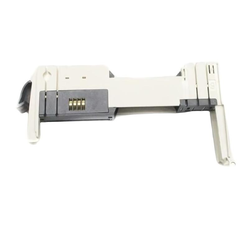
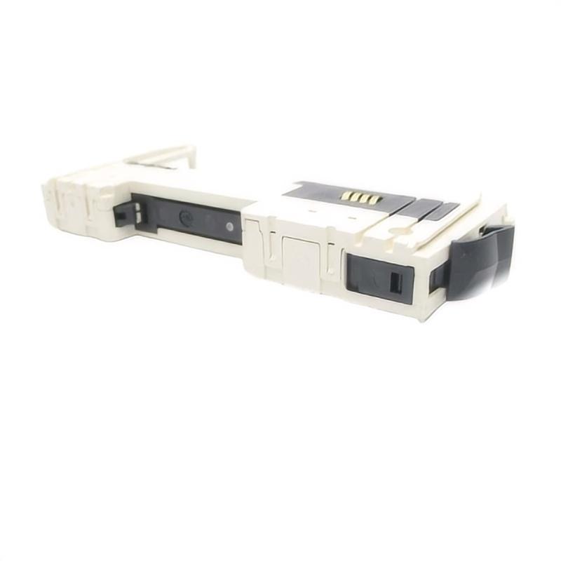
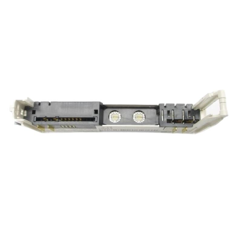
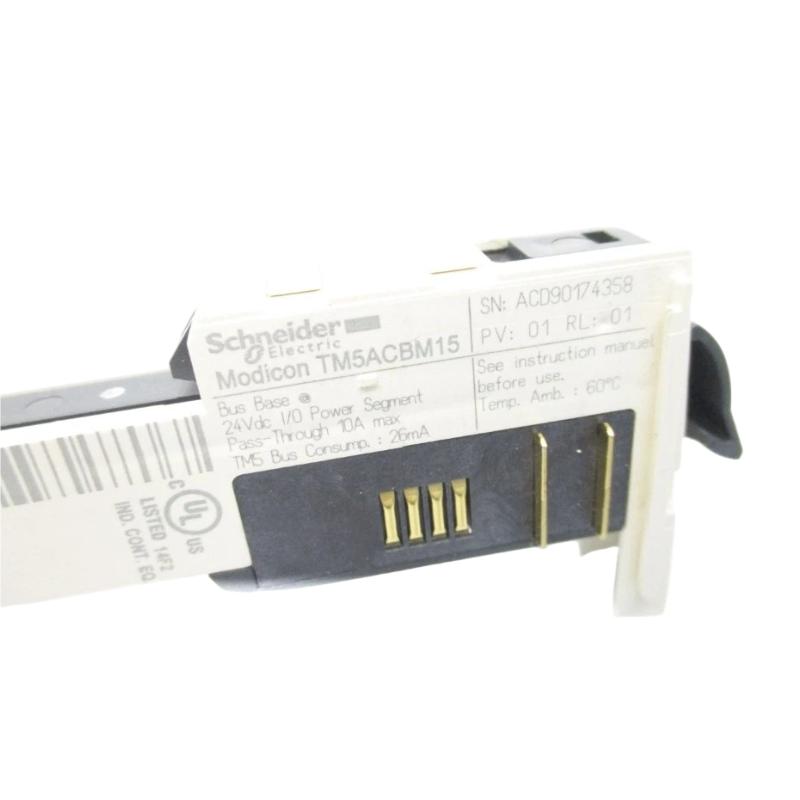
- Schneider
- TM5ACBM15
- Bus Base Module
- France
- 99 × 38 × 75 mm
- 0.08 kg
- Xiamen, China
- New & In Stock
- T/T, PayPal, Western Union
- 1 Year
- 1-3 Working Days
- DHL, UPS, TNT, FedEx and EMS.
- 24-Hour Service
- COO
- 5
Our advantage

Global Logistics
We have a 10-year logistics and express cooperation agreement, so our products can be shipped to any place in the world.

Brand new and original
Our products are imported in bulk from the place of origin. Because of the cooperative relationship, our products are all original and 100% new.

24-hour service
We provide 7*24 hours service to our customers. We will be there whenever you need us.

Price advantage
All our products are priced very favorably because we have our own warehouse and supply.
| Company Information | |||
| [email protected] | |||
| Mobile | +8615980777398 | ||
| +8615980777398 | |||
| 15980777398 |
Product Overview
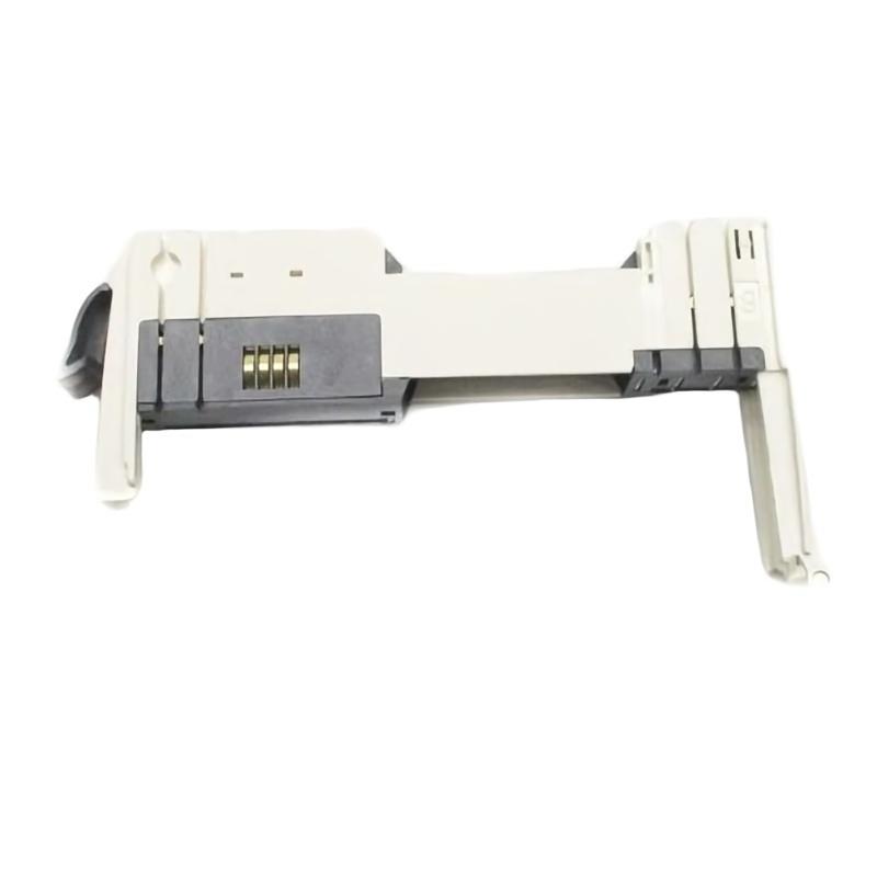
The Schneider Electric TM5ACBM15 Bus Base Module is an industrial automation component designed to support module interconnection within a compatible control-system architecture. Bus base modules provide a physical and electrical interface between associated automation components, helping establish the connections required for modular system assembly and signal exchange.
In industrial automation, modular control systems are widely used in machinery, packaging equipment, production lines, and distributed machine-control applications. These systems combine controllers, input and output modules, communication interfaces, and other functional components to perform coordinated operations. A suitable bus base module helps provide the necessary connection arrangement for the intended hardware configuration.
The TM5ACBM15 is identified by the supplied product description as a bus base module in Schneider Electric’s TM5 product family. Its compact dimensions of 99 × 38 × 75 mm and listed weight of 0.08 kg make it suitable for applications where compact modular construction and organized control-cabinet installation are important.
The exact electrical role, supported module combinations, connection arrangement, and installation requirements should be verified against the complete product designation and the applicable hardware documentation before installation. Not every base module is interchangeable with other components in the same product family, even when their external dimensions appear similar.
Technical Specifications
| Parameter | Specification |
|---|---|
| Manufacturer | Schneider Electric |
| Model | TM5ACBM15 |
| Product Type | Bus Base Module |
| Product Family | Schneider Electric TM5, as identified by the supplied description |
| Primary Function | Module base and interconnection interface |
| System Role | Supports modular hardware integration |
| Dimensions | 99 × 38 × 75 mm |
| Weight | 0.08 kg |
| Installation | Compatible modular automation assembly; verify mounting requirements |
| Typical Application | Industrial automation and modular control systems |
| Hardware Compatibility | Confirm the supported module combinations before installation |
The dimensions and weight above reflect the supplied product information. Specific bus architecture, electrical ratings, terminal assignments, supported neighboring modules, and diagnostic functions should be confirmed from the exact hardware documentation rather than inferred from the model name.
What Is the Schneider TM5ACBM15?
A bus base module is a hardware component used to establish an interconnection point within a modular automation system. Depending on the system design, a base may provide mechanical support, electrical contacts, or a defined connection interface for associated modules.
In a modular control architecture, the controller and its related components must be assembled in a configuration that allows the required power, signals, and system data to reach the appropriate devices. A correctly matched base or interconnection component helps maintain this arrangement.
The TM5ACBM15 is described as a bus base module. Its exact function within a particular installation depends on the compatible Schneider Electric hardware with which it is used. Before selecting it for a new installation or replacement, the complete order number and the intended system configuration should be checked.
A simplified modular arrangement can be represented as:
Controller and Interface Hardware → Compatible Base and Interconnection Components → Associated Automation Modules → Field Devices
This is a general illustration of modular automation architecture, not a verified terminal-level connection diagram for the TM5ACBM15.
Function and Working Principle
1. Modular Hardware Interconnection
Industrial control systems often use separate modules for different tasks. A base or interconnection component helps establish the physical arrangement required by the supported hardware.
The precise connection method depends on the module design. Correct component selection is important to ensure that the assembled system follows the intended mechanical and electrical configuration.
2. Electrical Connection Support
Where the base design includes electrical contacts or bus connections, it helps provide the connection path required by the compatible modules. The permitted voltage, current, and signal characteristics depend on the specific hardware.
The TM5ACBM15 should therefore be installed only in an arrangement approved for this exact model. Its electrical characteristics should not be assumed from the general term “bus base module.”
3. Support for Modular System Assembly
A modular automation system allows individual hardware components to be arranged according to the application. A compatible base can help maintain the correct physical layout and module relationship.
This arrangement can simplify the organization of compact control panels and make individual components easier to identify during maintenance.
4. Contribution to System Reliability
A properly installed base or interconnection component helps maintain secure connections between the hardware elements it supports. Incorrect mounting, contamination, damage, or an incompatible module combination may interrupt the intended connection and affect system operation.
For this reason, the base should be inspected during installation and maintenance, particularly when a control-system fault appears after modules have been replaced or rearranged.
Role in Industrial Control Systems
The TM5ACBM15 can be considered within the broader context of modular industrial automation. Modern control systems frequently separate processing, signal acquisition, output control, and communication functions into dedicated hardware components.
The interconnection arrangement between these components is important because the control system depends on correct hardware assembly and compatible electrical interfaces.
| System Element | Typical Role |
|---|---|
| PLC or Machine Controller | Executes application logic and coordinates machine operations |
| Bus Base Module | Provides the base or interconnection function specified for compatible hardware |
| Digital Input Module | Acquires discrete signals from switches and sensors |
| Digital Output Module | Provides discrete control signals to compatible devices |
| Analog Input Module | Acquires supported continuous process signals |
| Analog Output Module | Provides supported variable control signals |
| Communication Interface | Connects compatible devices through the intended network |
| Terminal Blocks | Organize field wiring and external connections |
| Industrial Power Supply | Provides appropriately rated control power |
| HMI Panel | Displays machine status, alarms, and operating information |
This table describes common roles within a modular control system. It does not confirm that every listed component can be directly connected to the TM5ACBM15. Actual compatibility must be established using the relevant product documentation.
Industrial Applications
Machine Automation
Modular control hardware is commonly used in industrial machinery that requires coordinated processing, input acquisition, and output control. A compatible base component can support the physical organization of the control assembly.
Applications may include automated production equipment, assembly machines, and dedicated machine-control panels.
Packaging Equipment
Packaging machinery often combines multiple control functions in a compact enclosure. Modular hardware arrangements help organize the components responsible for sensing, sequence control, and machine operation.
Correct interconnection is important when maintaining or expanding the control assembly.
Material Handling Systems
Conveyor systems, transfer stations, and automated handling equipment may use modular control hardware to coordinate sensors, motors, actuators, and operator interfaces. Base and connection components must match the selected automation platform.
Manufacturing and Assembly Lines
Manufacturing equipment frequently requires separate modules for different input, output, and control functions. A suitable modular assembly helps keep the control cabinet organized and supports maintenance access.
Industrial Process Equipment
Certain process machines use modular controllers to monitor equipment status and coordinate operating sequences. The bus base module’s suitability depends on the system architecture and the exact hardware combination.
Compact Control Cabinets
The supplied dimensions of 99 × 38 × 75 mm are useful when evaluating physical space requirements. Actual clearance must also account for adjacent modules, wiring, connectors, ventilation, and the manufacturer’s installation instructions.
Installation and System Integration
Correct installation begins with confirming the identity of the base module and the components with which it is intended to operate.
Verify the Product Identification
Check the complete model designation TM5ACBM15 on the product label and compare it with the hardware list for the control system.
Confirm the intended product family, revision where applicable, and approved module arrangement. Do not select a replacement based only on appearance or physical dimensions.
Confirm Module Compatibility
Before assembly, verify the supported neighboring modules, base arrangement, and any required accessories. A module that fits physically may still be electrically or functionally incompatible.
Where the system contains multiple base or connection components, follow the approved arrangement rather than substituting a visually similar part.
Inspect the Mounting Area
Check that the installation location is clean, secure, and appropriate for the hardware. Confirm that the mounting method and spacing follow the relevant instructions.
Keep the base free from dust, metal particles, moisture, and other contamination that could interfere with contacts or mechanical seating.
Follow Electrical Safety Procedures
Before installing or removing control-system hardware, isolate power where required and follow the machine’s lockout and safety procedures. Verify that the system is in a safe condition before handling electrical connections.
Use appropriate electrostatic-discharge precautions when handling sensitive electronic equipment.
Assemble the Hardware Correctly
Position the base and associated modules according to the approved installation arrangement. Ensure that mechanical engagement and electrical contacts are properly seated where applicable.
Do not force components together. Resistance during assembly may indicate incorrect orientation, incompatible hardware, damaged contacts, or an incorrect installation sequence.
Inspect and Commission the Assembly
After installation, inspect the assembled hardware and check that all components are correctly secured. Restore power according to the system commissioning procedure and review any available controller diagnostics.
If the system reports a hardware or communication fault, verify the complete hardware configuration before assuming that the base module itself is defective.
Troubleshooting the TM5ACBM15
Problems associated with a bus base module can resemble faults in the controller, connected modules, power supply, or overall system configuration. Troubleshooting should therefore consider the complete assembly.
Module Not Recognized
If a connected module is not recognized by the control system, possible causes include an incompatible hardware combination, incorrect assembly, damaged contacts, or an incorrect hardware configuration.
Check the product labels and compare the installed arrangement with the approved system configuration. Inspect the mounting and connection points after following the required power-isolation procedure.
Intermittent Hardware Faults
Intermittent faults may be associated with loose connections, mechanical movement, contamination, damaged contacts, or an unstable supply elsewhere in the system.
Inspect the base and adjacent components for visible damage and verify that the assembly is securely mounted. Review controller diagnostics to determine whether the fault is associated with one module or several components.
System Fails to Start After Replacement
If a system fault appears after replacing a base or connected module, confirm that the replacement model is correct and that all associated components have been reinstalled in the intended positions.
Check the hardware configuration and any required commissioning steps. A physically similar replacement may not support the same module combination or connection arrangement.
Visible Damage or Contamination
Cracked housing, bent contacts, corrosion, or contamination can compromise mechanical fit or electrical connections.
Do not install a visibly damaged component. Follow the maintenance procedure for inspection and replacement, and investigate the cause of contamination or mechanical damage before returning the system to service.
Repeated Faults After Module Rearrangement
If faults occur after modules are moved or added, review the supported system configuration, component order, and required base arrangements.
Record the original configuration before making further changes. Repeatedly exchanging components without a structured test plan can make the original fault more difficult to identify.
Maintenance Recommendations
Routine inspection helps preserve the integrity of modular control hardware and can reduce avoidable downtime.
Inspect the housing and contacts. Look for cracks, deformation, corrosion, and contamination. Handle contacts carefully to avoid damage.
Check mechanical seating. Confirm that the base and associated modules remain correctly positioned and securely mounted.
Maintain a clean control cabinet. Control dust, moisture, and other contaminants in accordance with the equipment’s environmental requirements.
Review system diagnostics. Record recurring hardware faults and note whether they appear after maintenance, power cycling, or changes to the module arrangement.
Document hardware changes. Maintain an updated record of the installed model numbers, module positions, and approved configuration.
Use approved replacement parts. Confirm the exact model and compatibility before replacing the base or any connected module.
Maintenance should be performed by qualified personnel using the applicable isolation and handling procedures.
Compatible System Components
A bus base module is selected according to the architecture in which it operates. The following component categories illustrate the types of equipment that may be found in a modular automation installation.
| Component Category | Purpose |
|---|---|
| Compatible Schneider Electric Controller | Provides control processing |
| Supported TM5 Hardware | Forms the relevant modular control assembly, subject to verification |
| Digital Input Modules | Receive compatible discrete field signals |
| Digital Output Modules | Provide discrete control outputs |
| Analog Signal Modules | Handle supported analog input or output functions |
| Communication Components | Provide the supported system or network interface |
| Power Supply | Supplies the required electrical power |
| Terminal and Wiring Accessories | Organize electrical connections |
| HMI Equipment | Provides operator monitoring and interaction |
| Engineering and Diagnostic Tools | Support configuration and maintenance |
The specific components that can be used with the TM5ACBM15 must be confirmed against the exact model documentation. This list is a general description of modular control-system roles, not a verified compatibility list.
Replacement and Procurement Considerations
When purchasing a replacement for the Schneider Electric TM5ACBM15 Bus Base Module, confirm the exact product identification before placing an order.
Important checks include:
- Complete model number
- Product designation and applicable revision
- Intended hardware family
- Supported module combinations
- Mechanical mounting arrangement
- Electrical connection requirements
- Condition of contacts and housing
- Any accessories required for the installation
The supplied physical specifications are 99 × 38 × 75 mm and 0.08 kg. These values can support inventory management, shipping estimates, and preliminary cabinet-layout planning.
However, physical dimensions and weight do not establish electrical compatibility. If the base is being replaced as part of a fault repair, inspect the connected modules and the surrounding assembly to determine whether the underlying cause is a damaged base, a defective neighboring module, contamination, or an incorrect configuration.
Key Advantages
Compact Construction
The listed dimensions of 99 × 38 × 75 mm support preliminary planning for compact automation installations.
Support for Modular Hardware Organization
A correctly matched base component helps establish the required arrangement of compatible automation hardware.
Simplified Maintenance Planning
Accurate component identification and documented module placement can make inspections, replacement work, and system troubleshooting more efficient.
Integration Within a Defined Control Architecture
When selected for the intended system, a bus base module supports the physical and electrical organization required by the associated hardware.
Lightweight Design
With a listed weight of 0.08 kg, the component is lightweight for inventory handling and replacement logistics.
Technical FAQs
What is the Schneider TM5ACBM15?
The TM5ACBM15 is identified in the supplied product information as a Schneider Electric bus base module used in a compatible modular automation arrangement.
What is the function of a bus base module?
A bus base module provides the base or interconnection function defined for the supported hardware. Its precise mechanical and electrical role depends on the product design and the modules with which it is intended to operate.
What are the dimensions of the TM5ACBM15?
The supplied dimensions are 99 × 38 × 75 mm.
How much does the TM5ACBM15 weigh?
The supplied weight is 0.08 kg.
Can any TM5 module be installed with this base?
No. The supported module combinations and system arrangement must be confirmed from the exact product documentation. Shared product-family naming does not guarantee compatibility.
What can cause a fault after replacing a bus base module?
Possible causes include an incorrect replacement, incompatible connected hardware, improper seating, damaged contacts, contamination, or an incorrect hardware configuration.
Does the TM5ACBM15 independently control a machine?
A bus base module is generally an interconnection or mounting component rather than a standalone controller. The control functions are performed by the appropriate controller and associated automation hardware.
Can a similar-looking base module be used as a substitute?
Not without confirming compatibility. The complete model number, supported hardware combination, connection arrangement, and installation requirements should be checked before substitution.
Conclusion
The Schneider Electric TM5ACBM15 Bus Base Module is a modular automation component intended to support the interconnection and organization of compatible control-system hardware. Correct selection and installation are important for maintaining the intended assembly arrangement and ensuring reliable operation of the associated automation equipment.
With supplied dimensions of 99 × 38 × 75 mm and a weight of 0.08 kg, the component offers a compact physical profile for appropriate industrial control installations. Its exact electrical role and compatible module combinations should be verified against the complete product designation and applicable technical documentation.
For installation, maintenance, or replacement, confirm the model number, inspect the connection points, follow the approved hardware arrangement, and perform the required commissioning checks. These steps help reduce configuration errors and support reliable operation of the broader industrial automation system.