

ProductPRODUCT
Featured products
Contact Us
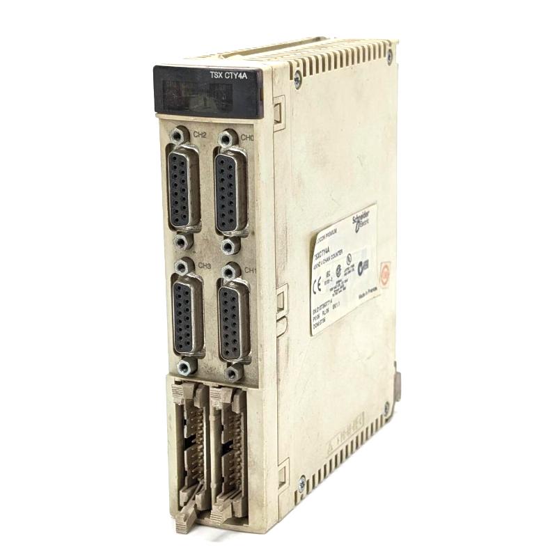
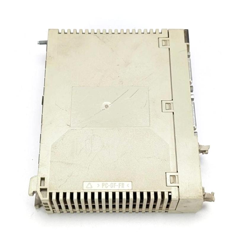
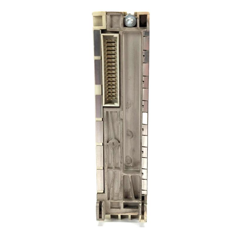
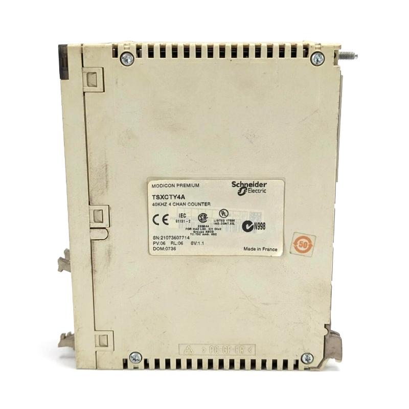
- Schneider
- TSXCTY4A
- Counter Module
- France
- 60 ×180 × 260 mm
- 0.43 kg
- Xiamen, China
- New & In Stock
- T/T, PayPal, Western Union
- 1 Year
- 1-3 Working Days
- DHL, UPS, TNT, FedEx and EMS.
- 24-Hour Service
- COO
- 6
Our advantage

Global Logistics
We have a 10-year logistics and express cooperation agreement, so our products can be shipped to any place in the world.

Brand new and original
Our products are imported in bulk from the place of origin. Because of the cooperative relationship, our products are all original and 100% new.

24-hour service
We provide 7*24 hours service to our customers. We will be there whenever you need us.

Price advantage
All our products are priced very favorably because we have our own warehouse and supply.
| Company Information | |||
| [email protected] | |||
| Mobile | +8615980777398 | ||
| +8615980777398 | |||
| 15980777398 |
Product Overview
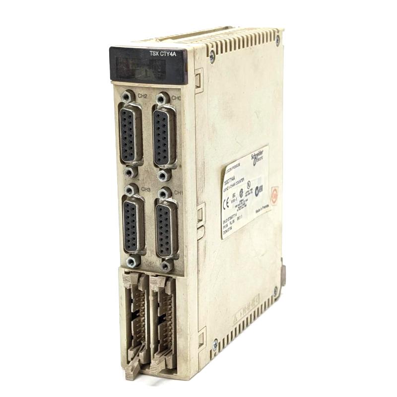
The Schneider Electric TSXCTY4A Modicon Premium 4-Channel Counter Module is a dedicated counting module for industrial automation systems built around the Modicon Premium PLC platform. It is intended for applications that need several independent counting channels to monitor production events, acquire pulse signals, and track movement from compatible sensors or encoders.
With four counter channels in one module, the TSXCTY4A can consolidate counting tasks that would otherwise require multiple single- or dual-channel modules. Typical applications include counting products on several conveyor lines, monitoring machine cycles, tracking rotary equipment, and acquiring pulse signals from production sensors.
The module works alongside the PLC CPU. It handles configured counting functions, while the CPU program uses the resulting values to coordinate machine sequences, compare production totals against targets, and respond to process events. Correct application setup depends on the input signal characteristics, counting mode, sensor wiring, and the requirements of the connected equipment.
Technical Specifications
| Parameter | Specification |
|---|---|
| Manufacturer | Schneider Electric |
| Model | TSXCTY4A |
| Product Family | Modicon Premium |
| Product Type | 4-Channel Counter Module |
| Number of Counter Channels | 4 |
| Application | Industrial pulse counting and event monitoring |
| Compatible Platform | Modicon Premium PLC system |
| Dimensions | 60 ×180 × 260 mm |
| Weight | 0.43 kg |
Product Features
- Four counting channels: Consolidates multiple counting tasks within one PLC module.
- Dedicated counting functions: Processes configured input pulses for production counting and machine monitoring.
- Multi-sensor applications: Allows separate counting tasks to be assigned to compatible field sensors, subject to channel configuration and electrical requirements.
- PLC program integration: Makes counter information available for machine sequencing, production totals, and event-based logic.
- Centralized installation: Reduces the need to distribute counting functions across several modules when four channels meet the application requirements.
- Industrial automation use: Suits equipment where repeatable pulse acquisition is required for monitoring or control.
- Structured troubleshooting: Channel-based organization helps maintenance personnel trace counting problems to the relevant signal path and application configuration.
The available counting modes, input frequency limits, sensor interfaces, and electrical characteristics must be matched to the actual module configuration. These parameters should not be inferred from the four-channel designation alone.
Working Principle
The TSXCTY4A receives pulse signals from compatible sensors or other field devices and processes them through its configured counter channels. The PLC application reads the counter information and uses it to determine when a production target, machine event, or operating condition has been reached.
Field Sensor → TSXCTY4A Counter Channel → Counter Value → Modicon Premium CPU → Control Sequence
For example, a production line may use separate sensors to count incoming products, completed assemblies, reject events, and machine cycles. Each signal can be assigned to an appropriate counting channel, provided the electrical interface and configuration meet the application’s requirements. The PLC program can compare these counts with preset production targets, calculate totals, and trigger related logic.
In a conveyor application, a sensor generates a pulse whenever a product passes a detection point. The assigned channel accumulates the pulses, and the CPU uses the count to track output or coordinate the next stage of the process. For encoder-based applications, the permitted signal type and counting mode must be confirmed before the module is integrated into the motion or measurement sequence.
Accurate counting depends on stable input signals, correct channel assignment, appropriate configuration, and a clear relationship between each pulse and the event being measured. The counter module performs the counting task; the wider PLC program determines how the results affect machine operation.
Role in a Modicon Premium Control System
The TSXCTY4A serves as the counting interface between field signals and the Modicon Premium PLC application. Its four channels allow several counting tasks to be managed within a single module, while the CPU handles overall machine logic and coordination.
| System Component | Function |
|---|---|
| Modicon Premium CPU | Executes the PLC application and coordinates machine operations |
| TSXCTY4A Counter Module | Processes configured counting signals across four channels |
| Photoelectric Sensor | Detects products or objects and generates counting pulses |
| Proximity Sensor | Detects machine positions or events for counting |
| Pulse-Generating Device | Supplies compatible pulses for a designated counting task |
| PLC Application Logic | Evaluates counter values and determines subsequent control actions |
| Output Modules | Operate external control devices according to the PLC sequence |
| HMI or Supervisory Interface | Displays production totals, counter status, or operating information when configured |
Before commissioning, verify that the module is compatible with the installed rack and CPU, and that the connected devices meet the applicable input requirements. Channel configuration should reflect the signal source and intended counting function.
Industrial Applications
| Application | Typical Function |
|---|---|
| Packaging Machinery | Counts products and tracks packaging-cycle events |
| Conveyor Systems | Monitors product flow across multiple detection points |
| Automated Assembly | Counts components and verifies production quantities |
| Material Handling | Tracks item movement and transfer events |
| Production Monitoring | Records machine cycles and compares actual output with targets |
| Sorting Equipment | Counts detected items at separate sorting or inspection stations |
| Machine Cycle Control | Uses pulse counts to trigger programmed sequence changes |
| Process Equipment | Monitors compatible encoder or sensor signals for counting tasks |
Installation and Maintenance
- Verify system compatibility. Confirm that the module is suitable for the installed Modicon Premium rack and CPU configuration.
- Isolate power before installation. Switch off the relevant power supplies before inserting the module or modifying field wiring.
- Identify the signal source. Determine whether each channel will receive signals from an incremental encoder, proximity sensor, photoelectric sensor, or other compatible pulse source.
- Check electrical compatibility. The TSXCTY4A supports compatible 5 V DC RS-422 incremental encoders, 10–30 V DC Totem Pole encoders, and specified 24 V DC PNP/NPN proximity sensors. Confirm the exact input requirements before connecting equipment.
- Connect the correct channel. Use the designated 15-pin SUB-D connector for each counting channel and the HE-10 connector for auxiliary signals, following the applicable wiring assignments.
- Configure the counting function. Select the appropriate up-counting, down-counting, or up/down-counting mode for the application.
- Check the input frequency. The module’s maximum counting frequency is 40 kHz. Confirm that the incoming pulse rate remains within this limit.
- Configure auxiliary signals. Set up preset, enable, and read functions according to the required machine sequence.
- Verify counter values. Test each channel separately and confirm that its count changes correctly when the sensor is activated.
- Check output behavior. If auxiliary outputs are used, verify their configuration and ensure that connected loads remain within the electrical limits.
- Review diagnostic indicators. Check the RUN, I/O, ERR, and channel LEDs during commissioning and troubleshooting.
- Inspect wiring periodically. Check connector security, cable condition, shielding, and routing near sources of electrical interference.
If a channel misses pulses, first inspect sensor alignment, signal voltage, wiring, and input frequency. If counts are consistently incorrect, check the selected counting mode and the relationship between each incoming pulse and the event being measured. For intermittent faults, examine grounding, shielding, connector condition, and possible electrical noise.
Related Components
| Component | Function |
|---|---|
| Modicon Premium CPU | Executes the PLC program and coordinates counting-based control sequences |
| Modicon Premium Rack | Provides the module mounting position and backplane connection |
| Incremental Encoder | Generates pulses corresponding to rotation or movement |
| Photoelectric Sensor | Detects products or objects for event counting |
| PNP/NPN Proximity Sensor | Detects machine positions or passing objects |
| Encoder Connection Cable | Carries encoder signals to the designated module connector |
| HE-10 Connection Cable | Connects auxiliary inputs, outputs, and associated signals |
| Shielded Signal Cable | Reduces susceptibility to electrical interference when correctly installed |
| External 24 V DC Supply | Supplies compatible field devices and auxiliary circuits where required |
Recommended Related Models
| Model | Product Type | Typical Application |
|---|---|---|
| TSXCTY2A | Modicon Premium 2-Channel Counter Module | Counting applications requiring two channels |
| TSXCTY4A | Modicon Premium 4-Channel Counter Module | Four-channel pulse counting and production monitoring |
| TSXCTY2C | Modicon Premium Measurement and Counter Module | High-speed measurement and encoder-based applications |
| TSXCAY41 | Modicon Premium Motion Control Module | Motion-control applications involving coordinated axis functions |
| TSXAEY414 | Modicon Premium Analog Input Module | Acquisition of analog process signals |
| Modicon Premium CPU Family | Programmable Logic Controllers | Processing counter data and coordinating machine logic |
Key Advantages
- Four counting channels in one module for multi-sensor applications.
- Counting frequencies up to 40 kHz for compatible input signals.
- Support for specified incremental encoder and PNP/NPN proximity sensor interfaces.
- Up-counting, down-counting, and up/down-counting functions.
- Auxiliary preset, enable, and read signals for application-level control.
- Channel and module status indicators for troubleshooting.
- Integration with Modicon Premium PLC programs for production monitoring and event-based control.
Technical FAQs
What is the maximum counting frequency of the Schneider TSXCTY4A module?
The TSXCTY4A supports a maximum counting frequency of 40 kHz. The incoming signal must remain within this limit, and the selected sensor or encoder must match the module’s electrical input requirements. For faster pulse applications, evaluate whether a dedicated high-speed measurement module is more appropriate for the required counting rate and control response.
How do you configure up-counting, down-counting, and up/down counting on the TSXCTY4A?
Select the counting mode that matches the application and the signal source. Up-counting accumulates pulses, down-counting decrements a counter from a configured value, and up/down counting allows the count to change in either direction according to the configured signals. The sensor arrangement, channel settings, and PLC application logic must work together to interpret the resulting counter value correctly.
Which sensors and encoders are compatible with the TSXCTY4A counter module?
The module supports specified 5 V DC RS-422 incremental encoders, 10–30 V DC Totem Pole incremental encoders, and compatible 24 V DC PNP/NPN proximity sensors. Photoelectric sensors can also be used when their output characteristics meet the applicable input requirements. Before wiring, confirm the signal type, voltage range, connector pin assignment, and required counting frequency.
How do you troubleshoot a TSXCTY4A channel that does not count incoming pulses?
Start by checking the sensor’s power supply, output signal, wiring, and connector assignment. Confirm that the selected input type matches the field device and that the signal frequency does not exceed the module’s counting limit. Next, review the channel configuration, enable conditions, and preset behavior. Use the module and channel diagnostic indicators to help distinguish a wiring or sensor problem from a configuration or module fault.