

ProductPRODUCT
Featured products

Contact Us
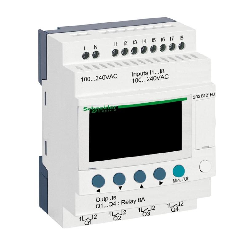
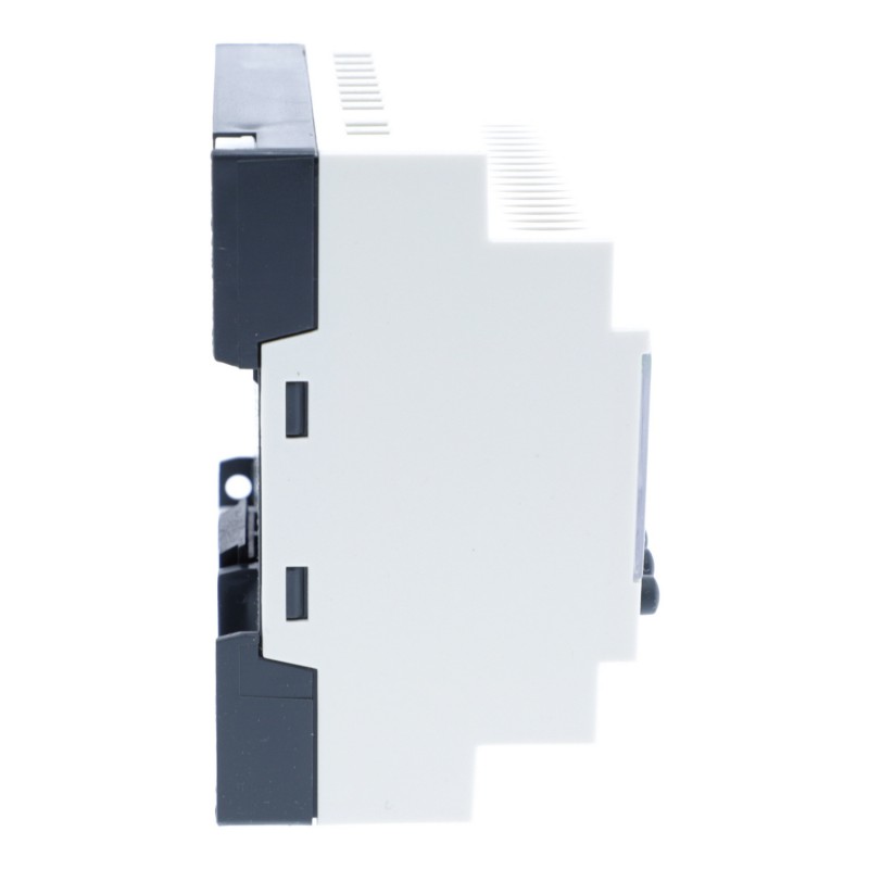
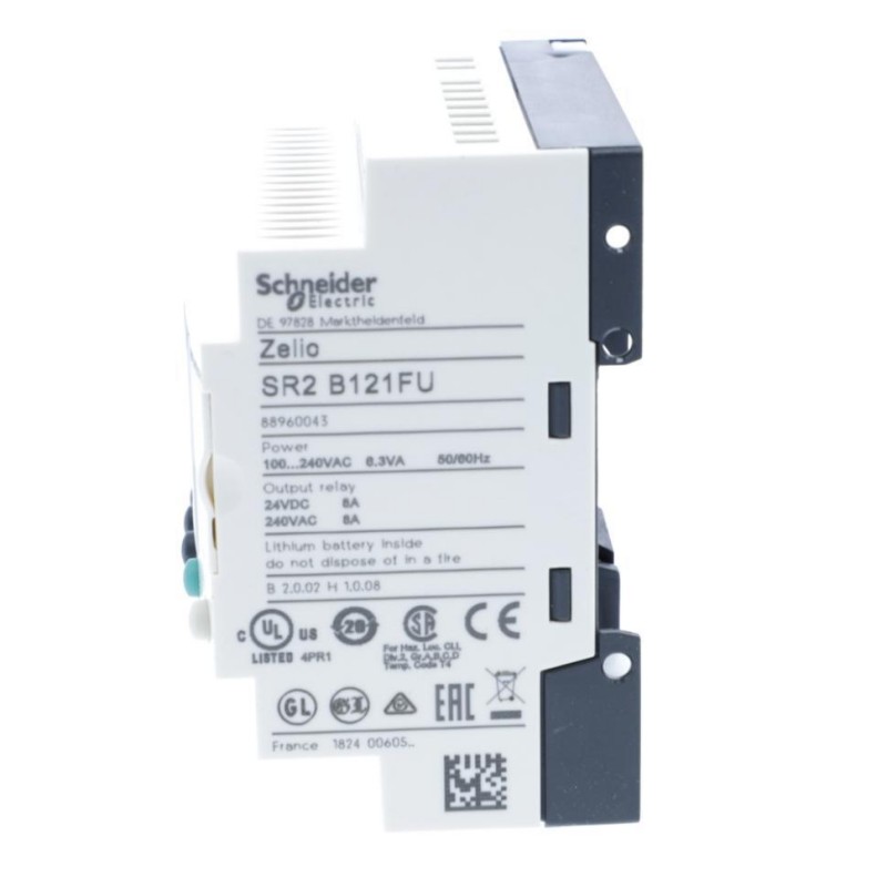
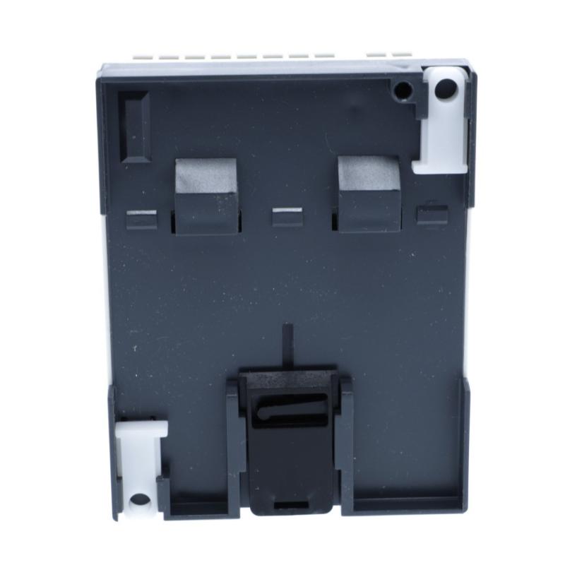
- Schneider
- SR2B121FU
- Compact Smart Relay
- France
- 107.6 × 71.2 × 59.5 mm
- 0.25 kg
- Xiamen, China
- New & In Stock
- T/T, PayPal, Western Union
- 1 Year
- 1-3 Working Days
- DHL, UPS, TNT, FedEx and EMS.
- 24-Hour Service
- COO
- 10
Our advantage

Global Logistics
We have a 10-year logistics and express cooperation agreement, so our products can be shipped to any place in the world.

Brand new and original
Our products are imported in bulk from the place of origin. Because of the cooperative relationship, our products are all original and 100% new.

24-hour service
We provide 7*24 hours service to our customers. We will be there whenever you need us.

Price advantage
All our products are priced very favorably because we have our own warehouse and supply.
| Company Information | |||
| [email protected] | |||
| Mobile | +8615980777398 | ||
| +8615980777398 | |||
| 15980777398 |
Product Overview
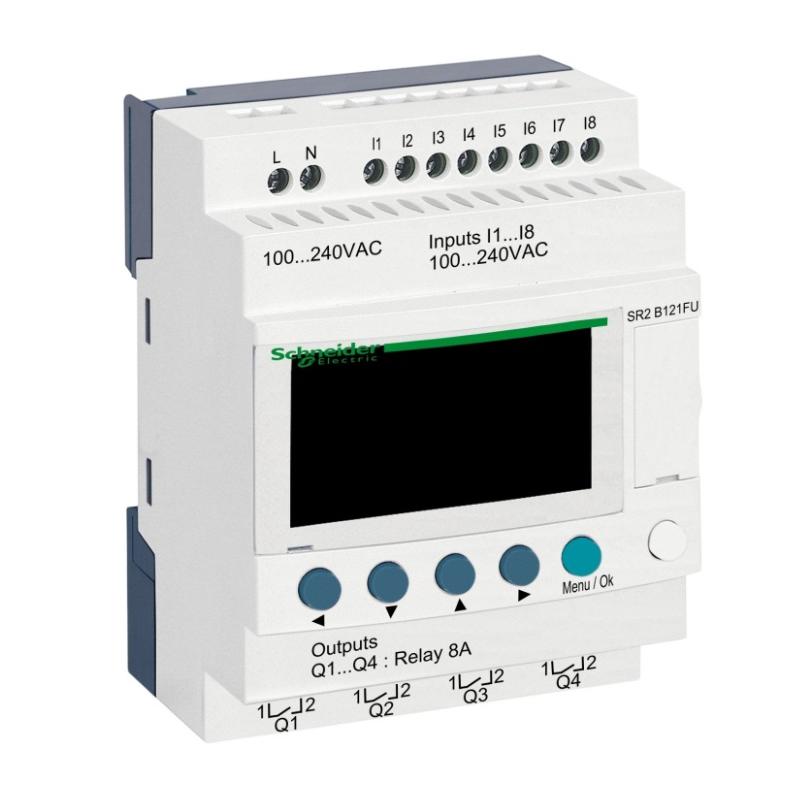
The Schneider Electric SR2B121FU is a Zelio Logic compact smart relay for small industrial machines, utility equipment, and standalone electrical control panels. It operates from a 100–240 V AC supply and combines eight discrete inputs, four relay outputs, an integrated LCD display, and a real-time clock. With 12 onboard I/O points, it is suited to applications that need programmable control and scheduled operation without the complexity of a larger PLC system.
The SR2B121FU is particularly useful in control panels where the available supply and field signals are AC-based. Its eight inputs accept compatible 100–240 V AC signals from switches, push buttons, limit switches, and auxiliary contacts. The four relay outputs switch external control circuits according to the programmed sequence, allowing the controller to coordinate contactors, interface relays, indicator lamps, and other compatible loads.
The built-in real-time clock distinguishes this model from related Zelio Logic smart relays without clock functionality. A lighting controller, for example, can use a programmed schedule to enable operation during specified periods while also responding to manual commands and interlocks. A ventilation control panel can combine scheduled operating periods with equipment status signals and operator inputs.
The integrated LCD and navigation buttons provide a local interface for accessing supported information and device functions. Programs can be developed using Zelio Soft, with ladder logic and function block diagram programming available for supported applications. Ladder logic is convenient for technicians familiar with conventional relay circuits, while function block diagrams offer another way to organize the operating sequence.
For a small pumping installation, the SR2B121FU can process float-switch signals, manual start and stop commands, and auxiliary feedback from external switching equipment. The programmed logic can coordinate pump operation and activate an alarm output when a specified condition occurs. The relay outputs operate the control circuits; motor power switching and electrical protection remain the responsibility of appropriately rated external equipment.
The controller also retains its program in EEPROM memory for up to ten years at the specified reference temperature of 25°C. This helps preserve the application during a supply interruption and simplifies restoration of the control program after an unexpected shutdown. Maintaining a separate program backup remains useful for controller replacement and future maintenance.
One important selection detail is that the SR2B121FU does not provide analog inputs. Its onboard inputs are intended for compatible discrete AC signals, not direct measurement of a 0–10 V or 4–20 mA process signal. Applications involving pressure transmitters, temperature transmitters, or continuous level measurements require a suitable signal-conversion arrangement or a controller with compatible analog input capabilities.
The four relay outputs also impose practical limits on the loads that can be switched directly. Contact voltage, current, inrush, switching frequency, and inductive-load characteristics must be considered when selecting the external circuit. A contactor or interface relay is appropriate where the controlled load exceeds the smart relay’s permitted switching capacity.
The SR2B121FU is therefore a suitable option for compact automation applications that need AC-powered digital inputs, programmable relay outputs, local display access, and clock-based scheduling. Its combination of these functions makes it useful for small machines and building-service control panels where the required signals are discrete rather than analog.
Technical Specifications
| Parameter | Specification |
|---|---|
| Manufacturer | Schneider Electric |
| Model | SR2B121FU |
| Product Family | Zelio Logic SR2 |
| Product Type | Compact Smart Relay |
| Rated Supply Voltage | 100–240 V AC |
| Supply Voltage Limits | 85–264 V AC |
| Supply Frequency | 50/60 Hz |
| Total I/O | 12 |
| Discrete Inputs | 8 |
| Discrete Input Voltage | 100–240 V AC |
| Discrete Input Current | 0.6 mA |
| Analog Inputs | 0 |
| Relay Outputs | 4 |
| Relay Output Voltage Limits | 24–250 V AC; 5–30 V DC |
| Output Contact Type | Normally Open |
| Local Display | Integrated LCD |
| Real-Time Clock | Yes |
| Programming Languages | Ladder Logic, Function Block Diagram |
| Program Memory Backup | Up to 10 years at 25°C |
| Maximum Supply Current | 80 mA at 100 V AC; 30 mA at 240 V AC, without extension |
| Power Consumption | 7 VA without extension |
| Mounting | 35 mm DIN Rail or Screw Fixing |
| Protection Rating | IP40 front panel; IP20 terminals |
| Dimensions | 107.6 × 71.2 × 59.5 mm |
| Weight | 0.25 kg |
Product Features
- 100–240 V AC power supply: Suits control panels built around an AC-powered control arrangement.
- Eight discrete inputs: Accepts compatible AC signals from switches, push buttons, and auxiliary contacts.
- Four relay outputs: Switches suitable external AC or DC control circuits within the permitted ratings.
- Integrated LCD display: Provides local access to supported device information and navigation functions.
- Built-in real-time clock: Supports scheduled operations and time-dependent control logic.
- Ladder logic programming: Allows control sequences to be developed using familiar relay-logic principles.
- Function block diagram programming: Provides an alternative method for organizing supported control functions.
- EEPROM program retention: Preserves the stored program for up to ten years at 25°C.
- No analog inputs: Keeps the onboard I/O arrangement focused on discrete signal processing.
- DIN rail or screw mounting: Supports installation in suitable electrical enclosures.
Working Principle
The SR2B121FU reads the states of its eight discrete inputs, evaluates the stored control program, and operates its four relay outputs according to the programmed conditions. Its real-time clock allows supported applications to incorporate schedules alongside ordinary input-driven logic.
100–240 V AC Supply → SR2B121FU → Program Execution → Relay Outputs → External Control Circuits
The input circuits receive compatible AC signals from field devices. A push button may provide an operating command, a limit switch may indicate a machine position, and an auxiliary contact may report the state of an external contactor. The controller evaluates these signals as part of the programmed sequence.
The program determines how each input affects the outputs. In a ventilation application, for example, a scheduled operating period may enable the fan-control sequence, while a stop command or an unmet interlock condition prevents the output from being activated. Additional logic can coordinate indicator lamps, alarms, and other auxiliary functions.
Ladder logic represents the control conditions through contacts, coils, and supported logic elements. Function block diagram programming uses connected functional blocks to implement the required operations. The choice depends on the programmer’s preferred method and the complexity of the application.
When an output condition becomes true, the corresponding relay contacts change state and switch the external control circuit. An output may energize a contactor coil, which then switches the power circuit for a motor or other load. The smart relay itself is not a substitute for a suitably rated contactor, overload protection, or required safety equipment.
The real-time clock allows the program to use supported time-based functions. For instance, an outdoor lighting controller can enable a lighting circuit during programmed operating periods while retaining manual control and interlock conditions. The clock provides a scheduling reference, but the application must still account for the intended operating sequence and any external conditions that affect safe operation.
The SR2B121FU uses AC discrete inputs rather than analog measurement channels. A field device that produces a continuous voltage or current signal cannot be connected directly as though the controller had analog input capability. Where process measurement is required, the system needs a compatible conversion arrangement or a controller designed for the relevant signal type.
During commissioning, each input should be tested against its actual field device, and each relay output should be checked against the intended program condition. The integrated display and programming software support local interaction and program management for the applicable functions.
EEPROM memory retains the application program for up to ten years at 25°C. After power returns, the controller’s behavior depends on its configuration and the state of the external control circuits. The machine should be arranged so that a supply interruption does not produce an unintended restart.
If a scheduled operation fails, the clock settings and relevant program conditions should be checked. If an input is not detected, inspect the field signal voltage and wiring. If an output command is present but the equipment does not operate, check the relay contacts and external load circuit separately.
Through discrete signal processing, programmable logic, clock-based functions, and relay switching, the SR2B121FU provides a practical control solution for compatible small automation systems.
Role in the Industrial Control Architecture
The SR2B121FU serves as the local programmable controller between AC field devices and external control circuits. It processes discrete input signals, applies the stored logic and supported time-based functions, and switches its relay outputs to coordinate the connected equipment.
AC Field Devices → SR2B121FU → Relay Outputs → Contactors and Control Loads
| System Component | Function |
|---|---|
| Schneider SR2B121FU | Executes programmed logic and controls four relay outputs |
| AC Control Supply | Provides the controller’s operating power |
| Push Buttons | Provide manual start, stop, and selection commands |
| Limit Switches | Report mechanical positions and travel limits |
| Auxiliary Contacts | Provide status feedback from external switching equipment |
| Real-Time Clock | Supplies time information for scheduled operations |
| Relay Outputs | Switch compatible external control circuits |
| Contactors | Switch motor and other power circuits |
| Interface Relays | Provide additional switching capacity where required |
| Circuit Protection Devices | Protect control wiring and connected equipment |
| Programming Computer | Supports application development and program transfer |
| Emergency Stop and Safety Devices | Implement required safety functions independently of ordinary control logic |
The smart relay handles the programmed sequence, while external switching equipment manages loads that require separate power circuits. Field-device voltage compatibility, output contact ratings, and the machine’s safety requirements must be considered when integrating the controller.
Industrial Applications
| Application | Typical Use |
|---|---|
| Lighting Control Panels | Operates compatible lighting circuits according to programmed schedules |
| Ventilation Systems | Coordinates scheduled fan operation with equipment status signals |
| Small Pumping Stations | Processes float-switch signals and controls pump contactors |
| Conveyor Systems | Coordinates discrete position signals and operating commands |
| Packaging Machinery | Manages simple sensor-driven sequences and auxiliary outputs |
| Building Services | Automates scheduled operation of compatible utility equipment |
| Access-Control Auxiliaries | Processes discrete commands and status contacts in suitable control circuits |
| Industrial Utility Equipment | Implements basic interlocks and time-dependent operation |
| Standalone Machine Panels | Consolidates conventional relay and timer logic into one programmable device |
| Small Assembly Machines | Coordinates operator inputs, limit switches, and scheduled functions |
Installation and Maintenance
- Verify the model reference: Confirm that the installed unit is SR2B121FU and that its 12-I/O arrangement matches the application.
- Prepare the control enclosure: Provide suitable mounting, wiring access, and environmental conditions for the IP20 terminal area.
- Install the controller: Use a compatible 35 mm DIN rail or the supported screw-fixing arrangement.
- Check the AC supply: Verify that the supply voltage and frequency are within the specified operating limits.
- Identify the input circuits: Label all eight input channels and confirm that connected field signals match the 100–240 V AC input requirements.
- Wire the relay outputs: Follow the terminal diagram and keep each connected load within the applicable contact and terminal limits.
- Review the external loads: Check voltage, current, inrush, and inductive characteristics before connecting contactors or other switching equipment.
- Develop the control program: Implement the required sequence using supported ladder logic or function block diagram programming.
- Configure the real-time clock: Set the clock and required scheduling functions for applications that use time-dependent operation.
- Test the input logic: Operate each field device and verify that the controller detects the expected input state.
- Verify output and restart behavior: Test relay responses, interlocks, scheduled operation, and the machine’s behavior after power restoration.
- Maintain program records: Keep the approved program, I/O assignments, clock settings, wiring diagrams, and commissioning results.
If an input is not detected, check the field signal voltage, terminal connection, and wiring arrangement. If a scheduled event does not occur, review the clock settings and program conditions. If an output does not operate the intended equipment, inspect the relay state and external load circuit before replacing the controller.
Related Components
| Component | Function |
|---|---|
| Schneider Electric SR2B121FU | Provides AC-powered programmable control with clock functions and four relay outputs |
| Schneider Electric SR2A101FU | Related 100–240 V AC smart relay with 10 I/O and no real-time clock |
| Schneider Electric SR2B201FU | Related 100–240 V AC smart relay with 20 I/O and real-time clock |
| Schneider Electric SR2B121BD | Related 24 V DC-powered smart relay with 12 I/O and real-time clock |
| Schneider Electric Zelio Soft | Software for developing and managing supported smart-relay programs |
| AC Control Supply | Supplies the controller and compatible AC control circuits |
| Field Switches | Provide discrete operating commands and status signals |
| Interface Relays | Switch compatible external loads where additional switching capacity is required |
| Contactors | Switch motor and other power circuits |
| Circuit Protection Devices | Protect control wiring and connected equipment |
| DIN Rail | Supports installation inside the electrical enclosure |
Recommended Related Models
| Model / Product Family | Product Type | Typical Application |
|---|---|---|
| Schneider Electric SR2A101FU | Zelio Logic Compact Smart Relay | 10 I/O, 100–240 V AC supply, display, no real-time clock |
| Schneider Electric SR2B121BD | Zelio Logic Compact Smart Relay | 12 I/O, 24 V DC supply, display, real-time clock |
| Schneider Electric SR2B201FU | Zelio Logic Compact Smart Relay | 20 I/O, 100–240 V AC supply, display, real-time clock |
| Schneider Electric SR2B201BD | Zelio Logic Compact Smart Relay | 20 I/O, 24 V DC supply, display, real-time clock |
| Schneider Electric Zelio Logic SR2 Series | Compact Smart Relay Family | Comparing I/O capacity, supply voltage, and clock functionality |
Key Advantages
- Combines eight AC discrete inputs and four relay outputs in one controller.
- Operates from a 100–240 V AC supply.
- Includes a real-time clock for supported scheduled operations.
- Provides an integrated LCD display for local interaction.
- Supports ladder logic and function block diagram programming.
- Retains the stored program in EEPROM under the specified conditions.
- Suits small automation systems using discrete signals and relay-based control.
Technical FAQs
How does the SR2B121FU handle scheduled control when an operator changes the operating state manually?
The built-in real-time clock supports programmed time-based functions, while the control program determines how scheduled conditions interact with manual commands and interlocks. The application should define the priority of these conditions so that manual operation produces the intended response without bypassing required safety arrangements.
Can the SR2B121FU read a 0–10 V pressure sensor or a 4–20 mA transmitter directly?
No. The SR2B121FU has eight discrete inputs and no analog input channels. Continuous voltage or current measurements require a compatible signal-conversion arrangement or a controller with the appropriate analog input capability.
What should be considered when using the relay outputs for frequent switching?
Frequent operation can affect relay contact life, especially with inductive loads and high inrush currents. The connected load must remain within the applicable contact ratings, and suitable suppression or external switching equipment should be used where necessary.
What is the significance of the SR2B121FU’s program backup specification?
EEPROM memory retains the stored application for up to ten years at 25°C. This helps preserve the program during a supply interruption, but it does not replace a separate program backup or the need to verify the machine’s behavior when power is restored.