

ProductPRODUCT
Featured products

Contact Us
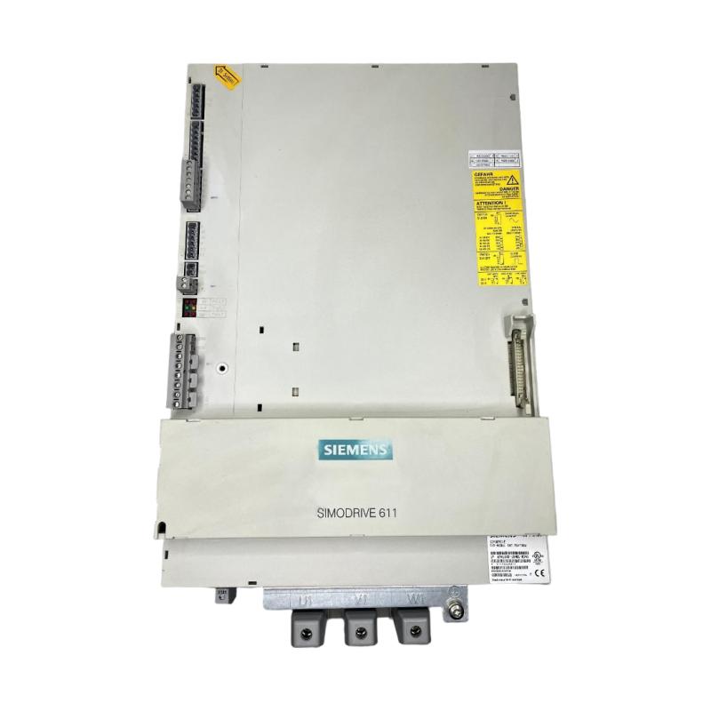
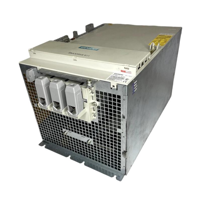
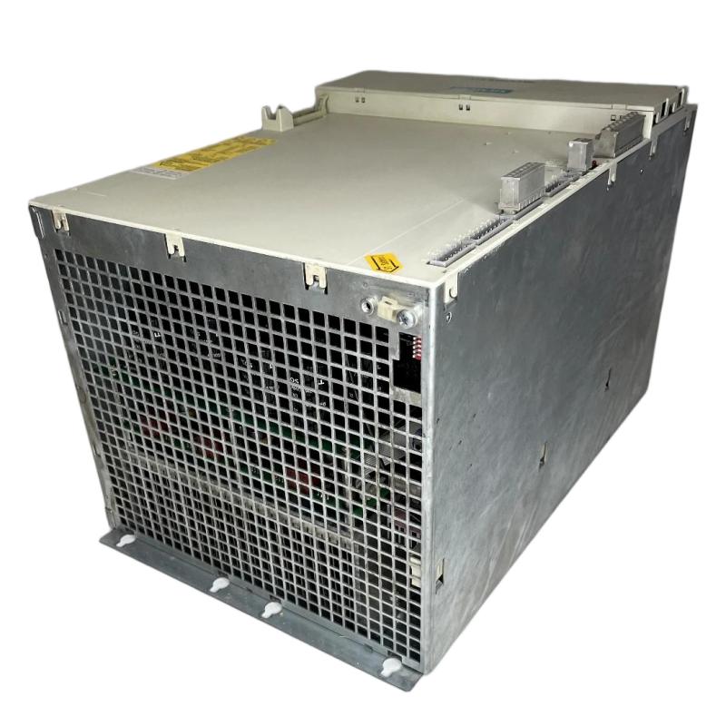
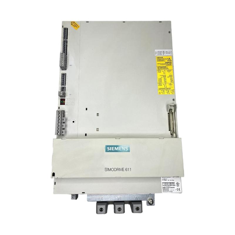
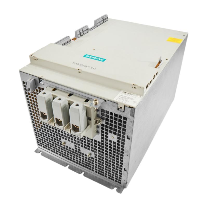
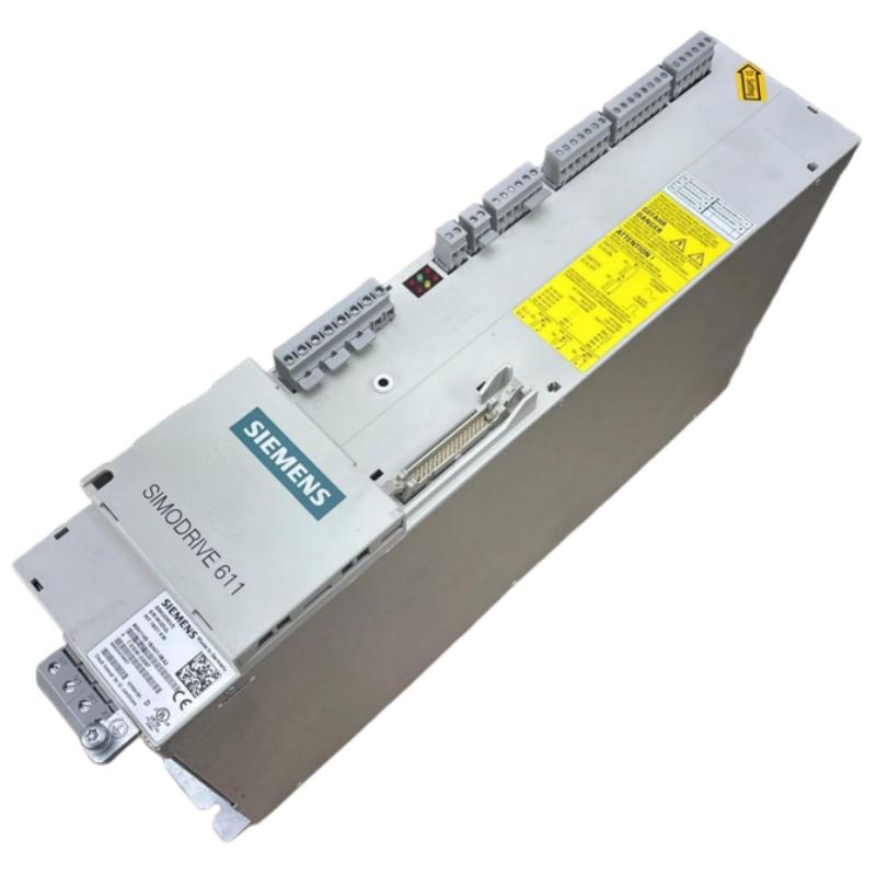
- Siemens
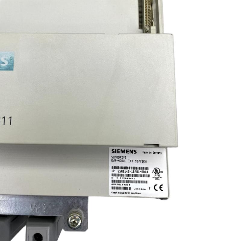
- 6SN1145-1BA01-0DA1
- Feed/Regenerative Feedback Module
- Germany
- 305 × 305 × 508 mm
- 21 kg
- Xiamen, China
- New & In Stock
- T/T, PayPal, Western Union
- 1 Year
- 1-3 Working Days
- DHL, UPS, TNT, FedEx and EMS.
- 24-Hour Service
- COO
- 4
Our advantage

Global Logistics
We have a 10-year logistics and express cooperation agreement, so our products can be shipped to any place in the world.

Brand new and original
Our products are imported in bulk from the place of origin. Because of the cooperative relationship, our products are all original and 100% new.

24-hour service
We provide 7*24 hours service to our customers. We will be there whenever you need us.

Price advantage
All our products are priced very favorably because we have our own warehouse and supply.
| Company Information | |||
| [email protected] | |||
| Mobile | +8615980777398 | ||
| +8615980777398 | |||
| 15980777398 |
1. Product Overview
The Siemens 6SN1145-1BA01-0DA1 Feed/Regenerative Feedback Module is an industrial drive-system component identified by its specific part number within the Siemens 6SN1145 product series. It is intended for evaluation in industrial automation and drive-system applications where reliable power-system integration, equipment compatibility, and long-term maintenance are important.
Industrial drive systems typically consist of several interconnected elements, including power-related modules, motor-drive units, motors, controllers, feedback devices, and electrical protection equipment. Each component must match the electrical and operational requirements of the overall installation. Selecting the correct module is therefore essential for maintaining system reliability and avoiding compatibility problems during equipment replacement or maintenance.
The product description identifies the 6SN1145-1BA01-0DA1 as a Feed/Regenerative Feedback Module. The exact operating characteristics, electrical ratings, and supported configurations should be confirmed using the technical documentation for this specific model. Similar part numbers within the same product family should not be considered interchangeable without verification.
The supplied mechanical specifications are 305 × 305 × 508 mm, with a listed weight of 21 kg. These details are useful for preliminary cabinet-layout planning, shipping preparation, handling arrangements, and spare-parts identification.
For maintenance engineers and industrial equipment buyers, the complete part number is an important reference when locating a replacement unit. Confirming the model, physical condition, electrical specifications, and intended system configuration can help reduce purchasing errors and unnecessary production downtime.
2. Technical Specifications
| Parameter | Specification |
|---|---|
| Manufacturer | Siemens |
| Model Number | 6SN1145-1BA01-0DA1 |
| Product Name | Feed/Regenerative Feedback Module |
| Product Series | Siemens 6SN1145 |
| Product Category | Industrial drive-system module |
| Dimensions | 305 × 305 × 508 mm |
| Weight | 21 kg |
| Primary Application Area | Industrial drive and automation systems |
| Electrical Input Ratings | Require model-specific verification |
| Rated Voltage | Not provided; verify from the nameplate |
| Rated Current | Not provided; verify from the technical documentation |
| Power Rating | Not provided; verify before system selection |
| Cooling Requirements | Confirm the applicable installation instructions |
| Connection Type | Verify against the original unit |
| Supported Drive Configuration | Requires confirmation |
| Mounting Arrangement | Verify using the actual unit and installation documentation |
| Operating Temperature | Requires verification |
| Protection Rating | Requires verification |
| Product Condition | Confirm whether new, refurbished, or used |
Specification note: The dimensions and weight listed above are based on the supplied product information. Other technical parameters have not been assumed because they were not provided.
3. Function and Working Principle
3.1 Role Within an Industrial Drive System
An industrial drive system converts and manages electrical energy to support controlled motor operation. Depending on the system architecture, the equipment may include supply-side power components, motor-drive modules, control electronics, feedback devices, and protective equipment.
A feed/regenerative module belongs to the broader category of drive-system power equipment. Its precise responsibilities depend on the electrical design and the configuration in which it is installed. For the Siemens 6SN1145-1BA01-0DA1, the exact circuit function and supported operating modes should be verified from the relevant Siemens documentation.
Understanding the distinction between power-related components and motor-control components is important during installation and troubleshooting. Components may have similar enclosures or belong to the same product family while serving different electrical functions.
Consequently, the 6SN1145-1BA01-0DA1 should be selected according to its documented function rather than its physical appearance alone.
3.2 Power Management During Machine Operation
Industrial machinery operates under changing load conditions. During acceleration, a motor requires energy to increase the speed of the mechanical load. During steady operation, the drive system must supply the power required by the machine. During deceleration, certain motor-drive arrangements can return electrical energy to the drive system.
In a regenerative drive architecture, returned energy may be managed or transferred through equipment specifically designed for that purpose. The actual energy path depends on the system topology, the connected components, and the operating limits of the equipment.
The term “Feed/Regenerative Feedback Module” identifies the product category supplied for this model, but it does not establish a specific rated power, efficiency, regeneration method, or supported drive combination. These details should be checked before engineering a new installation or replacing an existing component.
3.3 Relationship with Motion-Control Equipment
Motion-control applications often coordinate motors, drive electronics, controllers, and feedback devices to achieve the required speed, torque, or positioning performance.
The power-related components in such installations must be compatible with the complete system. Incorrect component selection can lead to connection problems, operating faults, or an inability to commission the equipment successfully.
Before incorporating the 6SN1145-1BA01-0DA1 into an existing machine, engineers should identify the connected drive modules, review the electrical diagrams, and confirm the supported system arrangement.
4. Role in Industrial Automation
4.1 Drive-System Integration
Industrial automation systems rely on coordinated electrical and control equipment. Drive-system components must work within the intended electrical architecture and meet the requirements of the connected machinery.
When evaluating the 6SN1145-1BA01-0DA1, engineers should confirm its exact function, electrical ratings, connection arrangement, and compatibility with the installed drive platform.
A successful integration process also considers cabinet space, cooling, grounding, electrical protection, maintenance access, and the operating environment.
4.2 Support for Existing Equipment
Many manufacturing facilities continue to operate established machinery that depends on specific drive-system components. When a module fails, identifying the correct replacement can be critical to restoring production.
The full model number should be checked carefully because closely related product variants may have different specifications. The suffix “0DA1” is part of the complete identification and should not be omitted when searching for a replacement.
Maintenance teams should record the original unit’s nameplate information, hardware identification, connector arrangement, and installation position before removing it. This information helps establish whether a proposed replacement matches the existing equipment.
4.3 Maintenance and Fault Diagnosis
A structured diagnostic process can help determine whether a drive-system module is responsible for a machine fault. Before replacing the component, technicians should review fault messages, operating history, recent maintenance work, electrical connections, and the condition of surrounding equipment.
A fault that appears to originate from a single module may also be associated with a supply problem, loose wiring, inadequate cooling, or an issue elsewhere in the drive system.
The 6SN1145-1BA01-0DA1 should therefore be assessed within the context of the complete installation. Replacing a component without identifying the underlying cause may not prevent the fault from recurring.
5. Industrial Applications
The exact approved applications for the Siemens 6SN1145-1BA01-0DA1 depend on its verified technical characteristics and the intended drive configuration. The following examples describe general industrial environments where drive-system power components may be relevant; they are not a model-specific approval list.
5.1 Machine Tools
Machine tools may use coordinated motor drives for spindle operation, feed motion, and precise positioning. Their drive systems must meet the machine’s electrical, mechanical, and dynamic requirements.
When evaluating this module for a machine-tool installation, engineers should verify the original system configuration and confirm that the module’s documented function matches the intended application.
5.2 Packaging Machinery
Automated packaging equipment may use multiple controlled movements for conveying, filling, sealing, cutting, and product handling. Drive-system reliability helps maintain production consistency and reduce interruptions.
Before replacing a component in packaging machinery, verify the complete model number, connection requirements, and compatibility with the existing drive architecture.
5.3 Material Handling Equipment
Conveyor systems, transfer mechanisms, and other material-handling machines rely on controlled motor operation to move products through production and distribution processes.
Drive-system components must be selected according to the connected motor, load conditions, and electrical configuration. Physical similarity alone is insufficient to establish suitability for the 6SN1145-1BA01-0DA1.
5.4 Automated Manufacturing Lines
Automated production lines often combine controllers, motors, drive modules, sensors, and other equipment. A failure in an important drive-system component can affect the operation of an individual machine or a larger production process.
Correct spare-parts identification, documented maintenance procedures, and appropriate replacement planning can help reduce unnecessary downtime.
5.5 Industrial Equipment Refurbishment
Refurbishment projects may involve replacing obsolete or damaged drive-system components while retaining much of the original machine infrastructure.
In these situations, engineers should evaluate the proposed module against the original equipment specifications. Electrical ratings, mounting arrangements, connections, cooling requirements, and system compatibility should be checked before installation.
6. Installation and System Integration
The following recommendations are general industrial installation considerations. They do not replace the model-specific installation instructions for the Siemens 6SN1145-1BA01-0DA1.
6.1 Verify the Product Identification
Before installation, confirm that the identification label shows the complete part number 6SN1145-1BA01-0DA1. Record any additional product identifiers or revision information available on the unit.
Compare the replacement with the original component and the relevant system documentation. Do not assume that a similar Siemens model is a direct substitute without technical confirmation.
6.2 Check Cabinet Space and Mechanical Requirements
The supplied dimensions are 305 × 305 × 508 mm, and the listed weight is 21 kg. These specifications should be considered when checking cabinet space, installation access, handling arrangements, and the mechanical support required for the equipment.
Confirm the actual enclosure dimensions, mounting points, orientation, and required service clearances before installation. The stated dimensions alone do not establish the complete mounting arrangement.
Because the module weighs 21 kg, suitable handling procedures should be used when transporting or positioning it. Avoid placing stress on connectors, terminals, or sensitive surfaces.
6.3 Confirm Electrical Ratings
Before connecting the module, verify its rated voltage, current, power requirements, protective devices, conductor specifications, grounding arrangement, and terminal assignments using the correct technical documentation.
Electrical ratings should not be inferred from the model number or the physical size of the equipment. Incorrect wiring or unsuitable protective devices can damage equipment and create serious hazards.
Installation and maintenance should be carried out by qualified personnel following applicable electrical safety procedures. Isolate the equipment from all relevant energy sources and verify the safe condition of the installation before handling electrical connections.
6.4 Review Cooling and Environmental Conditions
Drive-system equipment may require particular ventilation arrangements, temperature limits, humidity conditions, and protection against dust or other contaminants.
The applicable requirements for the 6SN1145-1BA01-0DA1 should be confirmed before installation. Ensure that the cabinet layout provides the specified airflow and that adjacent equipment does not obstruct required ventilation or maintenance access.
6.5 Inspect Wiring and Connectors
Before removing the original module, document the wiring and connector arrangement. Inspect accessible connections for looseness, deterioration, contamination, or evidence of overheating.
Use the correct electrical diagrams when reconnecting the replacement. Do not determine terminal functions solely from connector appearance or from the wiring arrangement of a different model.
6.6 Perform Commissioning Checks
After installation, complete the applicable inspection and commissioning procedures. Depending on the system, these may include checks of electrical connections, grounding, protective circuits, drive configuration, diagnostic indicators, and connected equipment.
Test the installation under controlled conditions before returning the machine to normal operation. Record the installed model, available revision information, test results, and any relevant diagnostic observations.
7. Compatible System Components
The following table identifies common component categories in industrial drive installations. It does not confirm that any specific component is compatible with the Siemens 6SN1145-1BA01-0DA1. Compatibility must be established from the actual system configuration and applicable technical documentation.
| Component Category | Typical Function | Compatibility Checks |
|---|---|---|
| Drive power supply equipment | Supplies electrical energy to the drive system | Confirm ratings and the approved power arrangement |
| Motor-drive modules | Control the operation of connected motors | Verify supported module combinations |
| Industrial motors | Convert electrical energy into mechanical motion | Check motor ratings and the intended drive configuration |
| PLC or motion controller | Coordinates machine sequences and motion commands | Confirm control architecture and required interfaces |
| Feedback devices | Provide speed or position information where required | Verify signal type and supported interfaces |
| Circuit protection equipment | Provides protection against specified electrical faults | Select according to the actual electrical design |
| Cabinet cooling equipment | Maintains suitable thermal conditions | Confirm the module’s ventilation and cooling requirements |
| Electrical cables and connectors | Provide power and signal connections | Follow the correct connection diagrams and specifications |
The final system configuration should be based on documented compatibility rather than general product-family similarities.
8. Recommended Models for Comparison
When sourcing a replacement, it may be useful to compare the original unit with other Siemens drive-system components. However, similar model numbers or a shared product family do not establish electrical or mechanical interchangeability.
| Model or Product Group | Comparison Purpose | Verification Required |
|---|---|---|
| Siemens 6SN1145-1BA01-0DA1 | Target model for identification and replacement | Confirm the full part number and nameplate details |
| Other Siemens 6SN1145-series modules | General product-family comparison | Verify exact function, ratings, and connection arrangement |
| Siemens 6SN1146-series modules | Broader drive-system comparison where relevant | Confirm the system architecture and supported combinations |
| Siemens SIMODRIVE-related components | Comparison for relevant legacy drive installations | Verify the installed platform and documented compatibility |
| Siemens SINAMICS drive components | Possible comparison group for modernization planning | Assess the complete system and migration requirements |
Important: These are comparison candidates, not confirmed direct replacements. Before substituting another module, verify the electrical ratings, physical interfaces, operating function, and supported drive configuration. For older installations, retaining the exact original model may be the most straightforward option when a suitable replacement is available.
9. Key Advantages for Maintenance and Spare-Parts Management
9.1 Precise Product Identification
The complete model number provides a clear reference for purchasing, maintenance documentation, and replacement planning. Including the full suffix helps distinguish this module from similar variants.
9.2 Practical Mechanical Planning
The supplied dimensions of 305 × 305 × 508 mm and weight of 21 kg provide useful preliminary information for storage, shipping, handling, and cabinet-layout planning. Actual mounting requirements should still be verified.
9.3 Support for Planned Maintenance
Maintaining accurate spare-parts records helps facilities prepare for component failures and organize replacement work. The records should include the full model number, product condition, available revision details, and the equipment in which the module is installed.
9.4 More Efficient Troubleshooting
Documenting fault messages, wiring arrangements, and the system configuration can help maintenance personnel investigate problems more systematically. This reduces the risk of replacing a component before the underlying fault has been identified.
9.5 More Reliable Procurement Decisions
A model-specific verification process helps reduce ordering errors. Confirming the part number, condition, physical dimensions, electrical characteristics, and compatibility provides a stronger basis for purchasing than relying on appearance alone.
10. Technical FAQs
Q1. What is the Siemens 6SN1145-1BA01-0DA1?
It is identified as a Siemens Feed/Regenerative Feedback Module in the 6SN1145 product series. Its exact electrical specifications and supported system configurations should be verified from the technical documentation for this model.
Q2. What are the dimensions of the 6SN1145-1BA01-0DA1?
The supplied dimensions are 305 × 305 × 508 mm. Confirm the actual enclosure measurements, mounting arrangement, and required clearances before planning an installation.
Q3. What is the weight of this module?
The supplied weight is 21 kg. Appropriate handling and support arrangements should be used during transportation, installation, and removal.
Q4. What is the rated voltage of the 6SN1145-1BA01-0DA1?
The rated voltage was not included in the supplied information. Check the module’s nameplate and the applicable technical documentation before connecting it to a power system.
Q5. What is its power rating?
The power rating cannot be established from the model number, dimensions, and weight alone. Verify the exact rating before selecting associated equipment or planning a replacement.
Q6. Can it replace another Siemens 6SN1145-series module?
Not automatically. Modules in the same series may differ in electrical specifications, connections, and intended functions. A replacement should be confirmed using the full part numbers and applicable documentation.
Q7. Is the 6SN1145-1BA01-0DA1 compatible with a SINAMICS system?
Compatibility should not be assumed from the manufacturer name alone. Verify the installed drive platform, module function, electrical requirements, and documented system combinations before considering integration.
Q8. What should buyers check before purchasing?
Confirm the complete part number, product condition, identification-label details, physical dimensions, available technical documentation, and compatibility with the installed equipment. For used or refurbished units, request clear product photographs and available inspection or test records.
Q9. Does this module support regenerative energy recovery?
The product description includes the term “Regenerative,” but the precise operating principle and supported energy-flow arrangement must be confirmed for this specific model and its intended system configuration.
Q10. What information is needed to verify a replacement?
Useful information includes the original unit’s nameplate, connected drive-module part numbers, wiring diagrams, motor specifications, and details of the existing drive architecture. This information helps determine whether a proposed replacement is suitable.
11. Procurement and Replacement Checklist
When sourcing the Siemens 6SN1145-1BA01-0DA1, buyers and maintenance teams should review the following points before completing an order.
- Full model number: Confirm that the label reads 6SN1145-1BA01-0DA1.
- Product condition: Establish whether the unit is new, refurbished, or used.
- Identification photographs: Request clear images of the product label and relevant connection areas.
- Technical documentation: Obtain available specifications and installation instructions for the exact model.
- Mechanical fit: Check the supplied dimensions against the cabinet and mounting arrangement.
- Electrical compatibility: Verify ratings, terminal assignments, protective requirements, and the supported system configuration.
- Testing records: For used or refurbished equipment, request available inspection and functional-test information.
- Shipping and handling: Account for the listed 21 kg weight and protect the equipment against impact and environmental damage.
- Return conditions: Clarify the supplier’s terms for incorrect identification or verified product issues.
For legacy automation systems, recording the installed module’s identification details and the surrounding equipment configuration can also simplify future maintenance and replacement work.
12. Conclusion
The Siemens 6SN1145-1BA01-0DA1 Feed/Regenerative Feedback Module is an industrial drive-system component that should be evaluated according to its verified specifications and the requirements of the complete automation installation.
The supplied product data identifies the module by part number 6SN1145-1BA01-0DA1, with dimensions of 305 × 305 × 508 mm and a weight of 21 kg. These details support product identification, preliminary mechanical planning, procurement, and handling preparation.
For replacement and maintenance projects, the essential steps are to confirm the complete model number, verify the electrical and mechanical requirements, check the existing system configuration, and follow the appropriate installation and commissioning procedures.
By using a model-specific verification process, industrial buyers, maintenance engineers, and system integrators can make better-informed decisions when sourcing or evaluating the Siemens 6SN1145-1BA01-0DA1 for industrial drive-system applications.