

ProductPRODUCT
Featured products
Contact Us
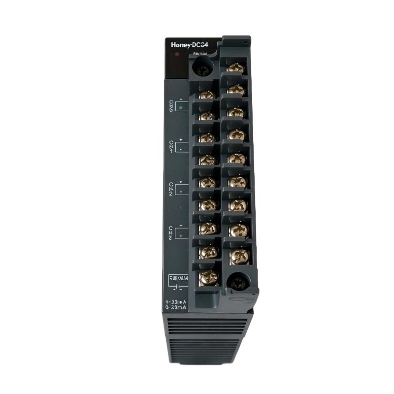
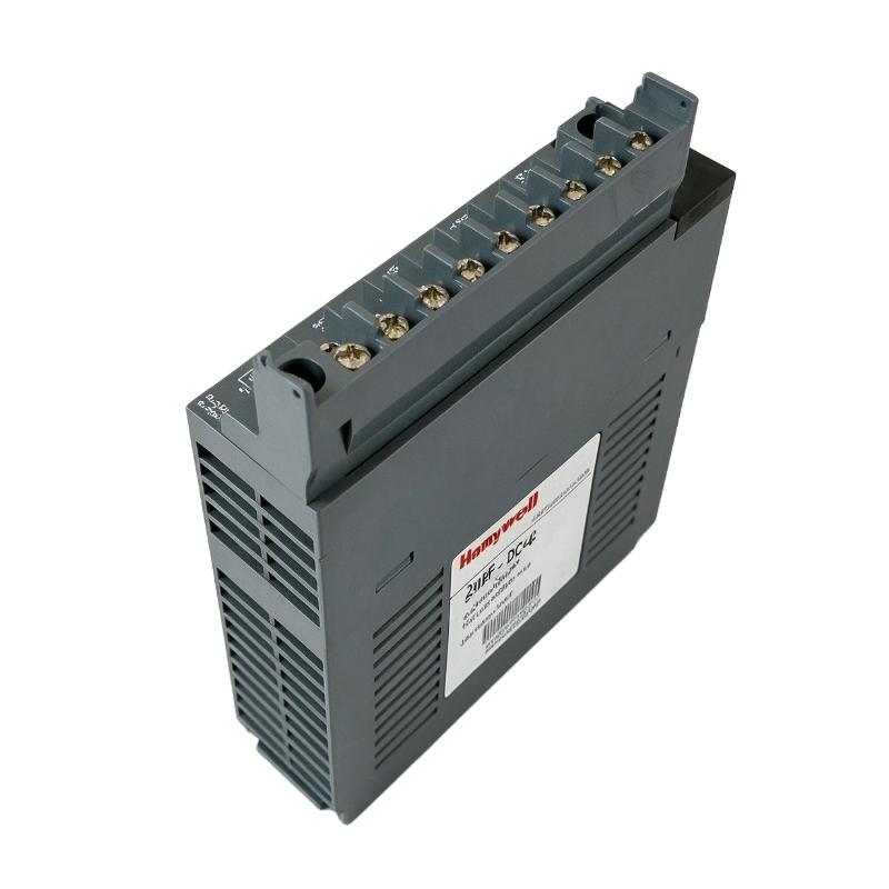
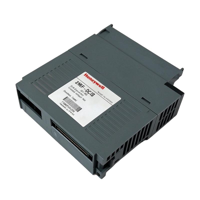
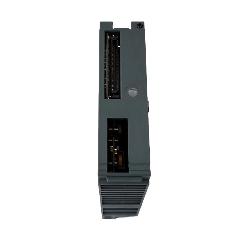
- Honeywell
- 2MLF-DC4S
- Analog Output Module
- USA
- 113 × 27 × 98 mm
- 0.15 kg
- Xiamen, China
- New & In Stock
- T/T, PayPal, Western Union
- 1 Year
- 1-3 Working Days
- DHL, UPS, TNT, FedEx and EMS.
- 24-Hour Service
- COO
- 4
Our advantage

Global Logistics
We have a 10-year logistics and express cooperation agreement, so our products can be shipped to any place in the world.

Brand new and original
Our products are imported in bulk from the place of origin. Because of the cooperative relationship, our products are all original and 100% new.

24-hour service
We provide 7*24 hours service to our customers. We will be there whenever you need us.

Price advantage
All our products are priced very favorably because we have our own warehouse and supply.
| Company Information | |||
| [email protected] | |||
| Mobile | +8615980777398 | ||
| +8615980777398 | |||
| 15980777398 |
Product Overview
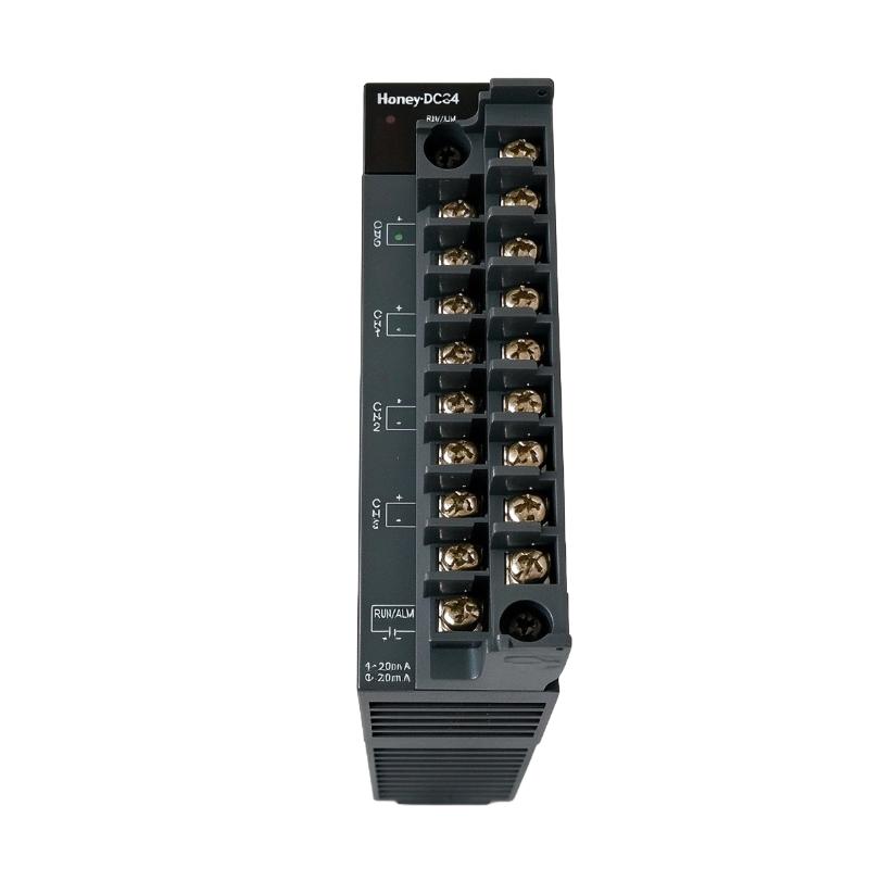
The Honeywell 2MLF-DC4S MasterLogic-200 Analog Output Module is a four-channel current output module used in MasterLogic-200 programmable logic controller systems. It converts digital output values from the PLC into analog current signals for field devices such as control valves, valve positioners, and other actuators that accept standard industrial current references.
A defining feature of the 2MLF-DC4S is the electrical isolation between its output channels. This arrangement is useful when several field devices operate in the same control system but require separate current-output circuits. The module supports selectable 4–20 mA and 0–20 mA output ranges, with the applicable range configured for each channel through the PLC program or module parameters.
The module is intended for applications in which a controller must regulate process equipment through continuous analog commands rather than simple ON/OFF signals. For example, a PLC can calculate a valve opening demand from process feedback and send the corresponding digital value to the 2MLF-DC4S. The module then generates the current signal used by the receiving field device.
When integrating or replacing this module, engineers should verify the selected output range, channel configuration, field wiring, and PLC I/O addressing. The output device must also be compatible with the selected current signal and the module’s load requirements. Correct configuration is essential to ensure that the commanded process value corresponds to the expected field response.
Technical Specifications
| Parameter | Specification |
|---|---|
| Manufacturer | Honeywell |
| Product Type | Analog Output Module |
| Model | 2MLF-DC4S |
| Product Series | MasterLogic-200 |
| Module Type | Isolated Current Output Module |
| Number of Output Channels | 4 |
| Analog Output Range | 4–20 mA, 0–20 mA |
| Maximum Load Resistance | 600 Ω |
| Digital Data Format | Signed 16-bit binary value, 14-bit data |
| Output Range Configuration | Configurable by program or module parameters for each channel |
| Channel Isolation | Isolation between output channels |
| Conversion Speed | 10 ms per four channels |
| Module Weight | 0.15 kg |
| Dimensions | 113 × 27 × 98 mm |
Product Features
- Four current output channels: Controls up to four compatible analog field-device inputs from one PLC module.
- Selectable current ranges: Supports 4–20 mA and 0–20 mA signals according to the configured application.
- Channel-to-channel isolation: Helps separate the electrical output circuits of individual channels.
- Software-based configuration: Allows output ranges and digital data formats to be configured for the respective channels.
- Digital-to-analog conversion: Translates PLC output values into continuous current signals for field-device control.
- Defined load capability: Supports output circuits with load resistance within the specified limit.
- MasterLogic-200 integration: Fits into the modular I/O architecture of compatible Honeywell PLC systems.
- Individual channel management: Supports channel-specific configuration and use according to the application program.
Working Principle
The Honeywell 2MLF-DC4S converts digital values generated by the MasterLogic-200 CPU into analog current outputs. Each channel operates as a configured output path between the PLC’s digital control data and a connected field device.
The CPU calculates the required process command from the control program. This value is transferred to the analog output module in the configured digital format. The module converts the value into the corresponding current signal, allowing the connected actuator or controller to respond proportionally to the requested operating condition.
For a typical 4–20 mA application, the lower and upper current values represent the configured endpoints of the control range. For example, a valve positioner may interpret 4 mA as the lower end of its commanded travel and 20 mA as the upper end, provided that the positioner is configured accordingly.
A simplified signal path is:
PLC Control Program → Digital Output Value → 2MLF-DC4S Conversion Circuit → Analog Current Signal → Field Device
The 0–20 mA range can also be selected where the receiving equipment supports that signal convention. The selected range must match the field-device configuration because using an incorrect range can produce an offset or incorrect process response.
The module supports signed 16-bit binary data with 14-bit data resolution as specified for this model. The interpretation of the digital value depends on the configured data format and output range. Engineers should ensure that the PLC program uses the correct scaling and numeric representation for each channel.
Isolation between channels helps prevent unwanted electrical interaction between separate output circuits. However, isolation does not remove the need for correct grounding, wiring practices, load selection, and compliance with the module’s electrical specifications.
Role in the MasterLogic-200 Control Architecture
The 2MLF-DC4S serves as the analog command interface between the MasterLogic-200 controller and connected field equipment. It allows the PLC to control process variables through continuous current signals rather than discrete switching commands.
A typical control arrangement is:
Process Sensors → PLC Input Modules → MasterLogic-200 CPU → 2MLF-DC4S → Current-Controlled Field Devices
| System Component | Function |
|---|---|
| MasterLogic-200 CPU | Executes the control program and calculates output commands |
| 2MLF-DC4S | Converts configured digital values into four analog current outputs |
| Analog Input Module | Receives process measurements from compatible transmitters |
| Digital Input Module | Receives discrete status and interlock signals |
| Field Control Valve | Adjusts process flow according to its input command |
| Valve Positioner | Converts the current reference into the required valve position |
| Variable Control Device | Accepts a compatible current reference for process regulation |
| PLC Base and Backplane | Provides the module installation and system interconnection |
| Field Wiring | Carries the analog current signals to the connected devices |
| Engineering Software | Supports PLC programming, I/O configuration, and troubleshooting |
The module generates output signals but does not independently determine the process control strategy. Its operation depends on the PLC program, correct I/O configuration, the selected signal range, and the response of the connected field device.
Industrial Applications
| Application | Typical Use |
|---|---|
| Process Control | Sending continuous control commands to analog field devices |
| Chemical Processing | Regulating valve position and other compatible process actuators |
| Water and Wastewater Treatment | Controlling valves and equipment that accept current-reference signals |
| Oil and Gas Facilities | Supporting analog control outputs in compatible automation systems |
| Industrial Boilers | Providing current commands to compatible modulating control equipment |
| Manufacturing Lines | Regulating process equipment requiring proportional control |
| HVAC Automation | Controlling compatible modulating valves and actuators |
| Pumping Systems | Providing analog references to compatible control equipment |
| Flow Regulation | Commanding valve position in flow-control loops |
| Pressure Control | Supporting pressure-regulating actuators through configured current outputs |
Application suitability depends on the field device’s input requirements, output loading, signal range, and control-system configuration. The module should be selected only when its current output capability and isolation arrangement match the application.
Installation and Maintenance
- Verify the module identity: Confirm the 2MLF-DC4S model and the intended installation location in the MasterLogic-200 system.
- Check the base and system configuration: Ensure that the PLC base, CPU, and module arrangement are compatible with the intended I/O configuration.
- Review the output signal range: Determine whether each connected field device requires 4–20 mA or 0–20 mA before configuring the channel.
- Confirm the PLC I/O assignment: Check the module’s I/O addressing and ensure that the control program writes to the intended output channels.
- Inspect field wiring: Verify terminal assignments, conductor condition, polarity where applicable, and the integrity of the connected output circuits.
- Check the load resistance: Confirm that the complete output circuit remains within the specified maximum load resistance of 600 Ω.
- Configure digital data formats: Ensure that the PLC program uses the correct numeric representation and scaling for the selected current range.
- Verify channel isolation requirements: Review the wiring arrangement for each channel and avoid introducing unintended electrical connections between separate output circuits.
- Inspect the module installation: Check that the module is seated correctly in its designated position and that the associated connections are secure.
- Test each output channel: Use an appropriate test procedure and measuring instrument to verify that the commanded digital value produces the expected current signal.
- Check field-device response: Confirm that the receiving actuator or controller responds correctly throughout the configured operating range.
- Record commissioning results: Document the output ranges, I/O assignments, measured current values, field-device response, and any corrective work performed.
Follow the applicable Honeywell safety and installation procedures before removing or installing the module. If an output is incorrect, check the program scaling, channel configuration, field wiring, load resistance, and receiving device before replacing the module.
Compatible System Components
The 2MLF-DC4S is intended for use within a compatible MasterLogic-200 PLC configuration. The following component categories support the overall control arrangement.
| Component | Function |
|---|---|
| Honeywell MasterLogic-200 CPU | Executes PLC logic and supplies digital output commands |
| MasterLogic-200 PLC Base | Provides the mounting and electrical interconnection for compatible modules |
| 2MLF-AC8A Analog Input Module | Receives current input signals from compatible field transmitters |
| 2MLF-AV8A Analog Input Module | Receives voltage input signals from compatible field devices |
| 2MLF-DV4A Analog Output Module | Provides four-channel voltage outputs for compatible applications |
| 2MLF-DC4A Analog Output Module | Provides four-channel current outputs without the DC4S channel-isolation designation |
| 2MLF-DC8A Analog Output Module | Provides eight-channel current outputs |
| Compatible Field Actuators | Receive current commands for proportional control |
| PLC Engineering Software | Supports program development and module configuration |
| Analog Signal Wiring | Connects the module outputs to field-device inputs |
Recommended Related Models
| Model | Product Type | Relevance |
|---|---|---|
| Honeywell 2MLF-DC4A | MasterLogic-200 Analog Current Output Module | Four-channel current output alternative |
| Honeywell 2MLF-DC8A | MasterLogic-200 Analog Current Output Module | Eight-channel current output module |
| Honeywell 2MLF-DC4H | MasterLogic-200 HART Analog Output Module | Four-channel current output with HART functionality |
| Honeywell 2MLF-DV4A | MasterLogic-200 Analog Voltage Output Module | Four-channel voltage output alternative |
| Honeywell 2MLF-AV8A | MasterLogic-200 Analog Voltage Input Module | Eight-channel voltage input module |
| Honeywell 2MLF-AC8A | MasterLogic-200 Analog Current Input Module | Eight-channel current input module |
Key Advantages
- Provides four analog current outputs from a single MasterLogic-200 module.
- Supports commonly used 4–20 mA and 0–20 mA control signals.
- Offers isolation between output channels for separately wired field circuits.
- Supports channel-specific output range and digital data configuration.
- Integrates analog field-device control into a modular PLC architecture.
- Helps reduce the number of separate output modules required for four-channel applications.
Technical FAQs
How should the output range be selected for the 2MLF-DC4S?
Select 4–20 mA or 0–20 mA according to the receiving field device’s input specification and the control strategy. The corresponding module configuration and PLC scaling must use the same range.
Does the 2MLF-DC4S provide isolation between its four output channels?
Yes. The DC4S model is specified as a current output module with isolation between channels. The actual wiring must still follow the module’s installation requirements and the field-device circuit design.
What happens if the field-device load exceeds 600 Ω?
A load beyond the specified maximum may prevent the module from delivering the intended output signal accurately. Check the resistance of the complete output circuit, including the receiving input and associated wiring, before commissioning.
Why might the measured current differ from the PLC command?
Possible causes include incorrect output scaling, an incorrectly selected current range, wiring faults, excessive load resistance, a field-device input problem, or a module fault. Compare the configured digital value with the measured output current to isolate the cause.