

ProductPRODUCT
Featured products
Contact Us
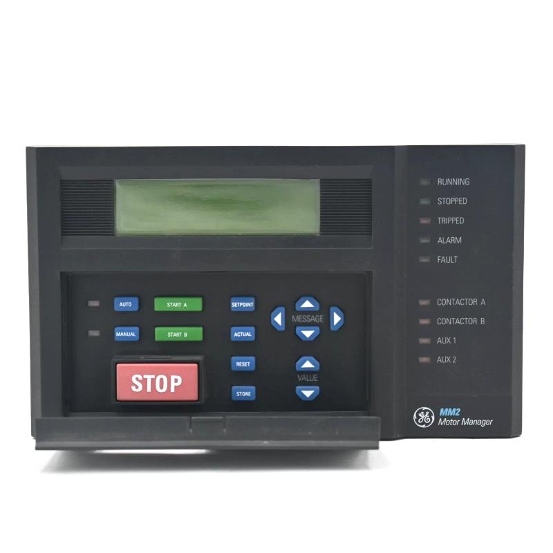
- GE
- MMII-PD-1-2-120
- Motor Protection System
- USA
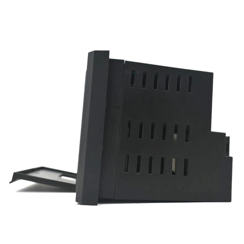
- 187 × 111 × 125 mm
- 1.8 kg
- Xiamen, China
- New & In Stock
- T/T, PayPal, Western Union
- 1 Year
- 1-3 Working Days
- DHL, UPS, TNT, FedEx and EMS.
- 24-Hour Service
- COO
- 5
Our advantage

Global Logistics
We have a 10-year logistics and express cooperation agreement, so our products can be shipped to any place in the world.

Brand new and original
Our products are imported in bulk from the place of origin. Because of the cooperative relationship, our products are all original and 100% new.

24-hour service
We provide 7*24 hours service to our customers. We will be there whenever you need us.

Price advantage
All our products are priced very favorably because we have our own warehouse and supply.
| Company Information | |||
| [email protected] | |||
| Mobile | +8615980777398 | ||
| +8615980777398 | |||
| 15980777398 |
Product Overview
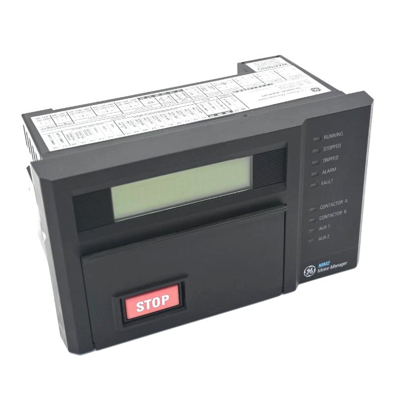
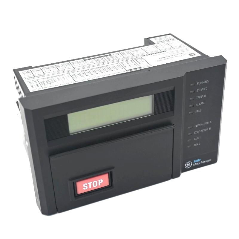
The GE MMII-PD-1-2-120 Multilin Motor Manager II Protection System is a dedicated motor protection and monitoring device for industrial motor applications. It operates at the motor protection layer, monitoring electrical and operating conditions and responding to configured protection requirements.
In a typical motor control system, the Motor Manager is installed between the motor measurement and control circuits and the higher-level automation system. It can monitor motor operating conditions, identify abnormal states, and provide protection-related status to the motor control architecture.
The unit is particularly relevant in applications where motor protection needs to be handled independently from PLC sequencing. Pumps, fans, compressors, conveyors, and other motor-driven equipment can use a dedicated protection device to supervise the motor while the PLC or DCS handles broader process control.
Technical Specifications
| Parameter | Specification |
|---|---|
| Product | GE MMII-PD-1-2-120 |
| Product Family | Multilin Motor Manager II |
| Product Type | Motor Protection System |
| Primary Function | Motor protection and monitoring |
| System Role | Dedicated motor protection interface |
| Application | Industrial motor control and protection |
| Physical Dimensions | 187 × 111 × 125 mm |
| Weight | 1.8 kg |
Product Features
- Part of the GE Multilin Motor Manager II protection platform.
- Provides dedicated monitoring and protection for industrial motors.
- Separates motor protection functions from higher-level PLC control logic.
- Can monitor motor-related electrical operating conditions.
- Provides protection status and event information for system diagnostics.
- Suitable for motor-driven pumps, fans, compressors, conveyors, and process equipment.
- Can interface with motor control and supervisory automation systems.
- Supports maintenance activities by providing protection-related operating information.
Working Principle
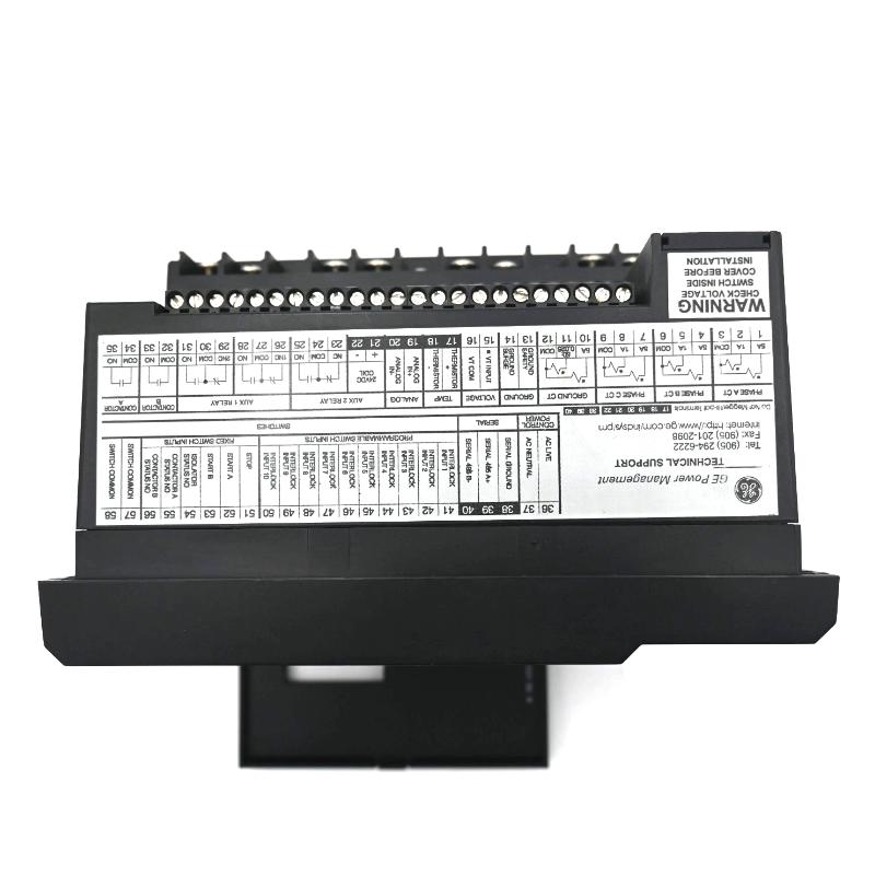
The MMII-PD-1-2-120 receives motor-related electrical measurements and operating information from the associated motor control circuit. The Motor Manager evaluates these conditions against its configured protection functions.
When an operating condition reaches a configured protection threshold, the protection system can generate the corresponding alarm or trip response through the connected motor control architecture. The resulting status can also be made available to a PLC, HMI, or supervisory system where the installation includes such integration.
The protection device should be viewed as a dedicated motor-monitoring layer rather than as a replacement for the PLC. The PLC can continue to manage machine sequencing and process interlocks, while the Motor Manager handles motor-specific protection functions.
For troubleshooting, identify the actual protection event first. A motor trip may originate from the motor, electrical supply, measurement circuit, wiring, configuration, or another connected component. Checking the protection information before replacing hardware can significantly narrow the fault location.
Role in a Motor Protection Control Architecture
| System Element | Function |
|---|---|
| Motor | Rotating electrical equipment being protected |
| Current / Voltage Measurement | Provides electrical operating information |
| MMII-PD-1-2-120 | Monitors motor conditions and executes configured protection functions |
| Motor Starter / Contactor | Controls motor energization and isolation |
| PLC / DCS | Handles machine sequencing and higher-level process control |
| HMI | Displays motor status, alarms, and diagnostic information |
| Plant Network | Provides supervisory communication where applicable |
The MMII-PD-1-2-120 occupies the dedicated protection layer:
Motor → Electrical Measurements → MMII-PD-1-2-120 → Protection / Trip Functions → Motor Control Circuit
For supervisory integration:
MMII-PD-1-2-120 → PLC / DCS / Network → HMI or Operator Station
This architecture allows motor protection to operate as a dedicated function while remaining connected to the wider automation system.
Industrial Applications
| Application | Typical Use |
|---|---|
| Motor Control Centers | Dedicated protection and monitoring of industrial motors |
| Pump Systems | Monitoring and protecting pump motors |
| Compressor Systems | Protecting motors driving compressors |
| Fan and Blower Systems | Supervising continuously operating motor loads |
| Conveyor Systems | Protecting motors used in material handling |
| Process Plants | Motor protection for process equipment |
| Manufacturing Lines | Monitoring motors used in production machinery |
| Utility Equipment | Protection of auxiliary and plant-service motors |
Installation and Maintenance
- Confirm Motor Compatibility
Verify that the MMII configuration matches the motor application and required protection functions. - Check Measurement Circuits
Inspect current, voltage, and other applicable measurement connections for correct wiring and secure termination. - Verify Protection Settings
Review configured protection parameters against the motor application and approved commissioning data. - Inspect Trip Wiring
Check the connections between the protection system and motor starter or contactor control circuit. - Verify Motor Operating Condition
Investigate the motor and electrical system when a protection event occurs instead of assuming the protection device has failed. - Review Diagnostic Information
Record protection events and alarms before resetting the system when practical. - Check Control Power
Inspect associated power connections if the device is unavailable, resets unexpectedly, or loses communication. - Inspect Communication Connections
When supervisory information is missing, check the communication path independently from the motor protection function. - Verify Configuration After Replacement
Load or confirm the appropriate configuration before returning a replacement device to service. - Inspect the Installation Environment
Check for excessive heat, moisture, contamination, vibration, or other conditions that could affect the protection equipment. - Follow Electrical Safety Procedures
Isolate the relevant motor and electrical circuits before working on protection wiring or associated equipment. - Perform Functional Verification
After maintenance, confirm protection status, motor-control interaction, alarms, and supervisory communication where applicable.
Related Components
| Component | Function |
|---|---|
| GE Multilin Motor Manager II | Provides motor protection and monitoring |
| Current Transformers | Supply motor-current measurement signals |
| Voltage Measurement Components | Provide electrical voltage information |
| Motor Starter | Controls motor starting and stopping |
| Contactors | Switch the motor power circuit |
| PLC / DCS | Provides higher-level control and sequencing |
| HMI | Displays motor operating and protection information |
| Industrial Motor | Equipment being monitored and protected |
Recommended Related Models
| Model / Product Family | Product Type | Typical Application |
|---|---|---|
| GE Multilin Motor Manager II | Motor Protection System | Industrial motor protection |
| GE Multilin Motor Protection Relays | Motor Protection Relay | Motor electrical protection |
| GE Multilin Protection Systems | Protection Equipment | Industrial electrical monitoring |
| GE Motor Control Equipment | Motor Control | Motor starting and switching |
| GE PLC Systems | Programmable Controller | Machine and process automation |
| GE Industrial HMI Systems | Operator Interface | Motor and process visualization |
Key Advantages
- Dedicated motor protection and monitoring.
- Separates motor-specific protection from PLC sequencing.
- Suitable for a range of industrial motor-driven equipment.
- Provides protection information useful for troubleshooting.
- Can integrate with broader motor control and supervisory architectures.
- Suitable for maintaining existing Multilin Motor Manager II installations.
Technical FAQs
What is the primary purpose of the MMII-PD-1-2-120?
The MMII-PD-1-2-120 is part of the GE Multilin Motor Manager II family and serves as a dedicated motor protection and monitoring system. It evaluates motor-related operating conditions and performs configured protection functions.
How does the Motor Manager differ from a PLC?
The Motor Manager focuses on motor-specific protection and monitoring, while a PLC generally executes machine sequencing, interlocks, and broader automation logic. The two devices can operate together within the same control architecture.
What should be investigated when the MMII-PD-1-2-120 trips a motor?
Identify the protection event or alarm first, then check the corresponding motor condition, electrical supply, measurement circuit, field wiring, and protection settings. A trip should be treated as a protection event requiring investigation rather than automatically as evidence of a failed Motor Manager.
What should be verified when replacing the MMII-PD-1-2-120?
Verify the exact model and configuration, measurement wiring, motor-control connections, protection settings, control power, and any communication interfaces used by the existing system. After replacement, perform a controlled functional test of protection and motor-control functions.