

ProductPRODUCT
Featured products
Contact Us
- Foxboro
- P0972VG
- Fiber Optic Cable
- USA
- 0.5 meters
- 3 kg
- Xiamen, China
- New & In Stock
- T/T, PayPal, Western Union
- 1 Year
- 1-3 Working Days
- DHL, UPS, TNT, FedEx and EMS.
- 24-Hour Service
- COO
- 6
Our advantage

Global Logistics
We have a 10-year logistics and express cooperation agreement, so our products can be shipped to any place in the world.

Brand new and original
Our products are imported in bulk from the place of origin. Because of the cooperative relationship, our products are all original and 100% new.

24-hour service
We provide 7*24 hours service to our customers. We will be there whenever you need us.

Price advantage
All our products are priced very favorably because we have our own warehouse and supply.
| Company Information | |||
| [email protected] | |||
| Mobile | +8615980777398 | ||
| +8615980777398 | |||
| 15980777398 |
Product Overview
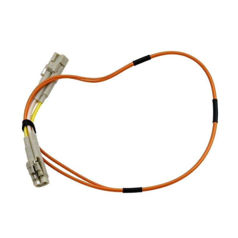
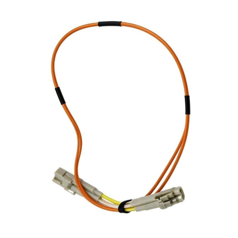
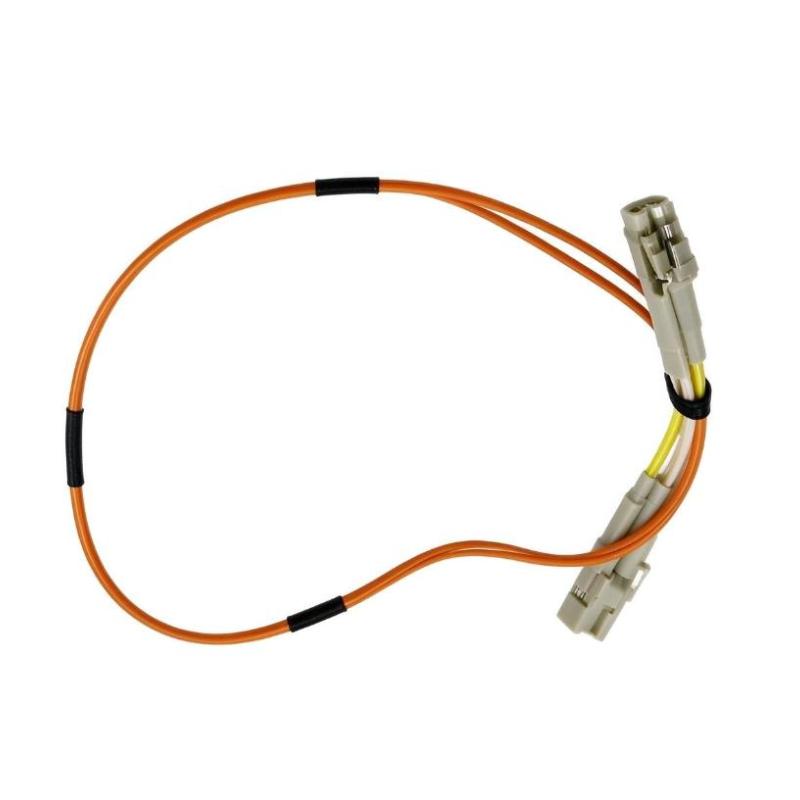
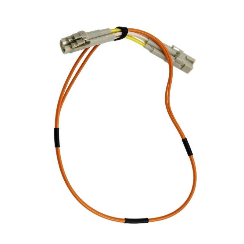
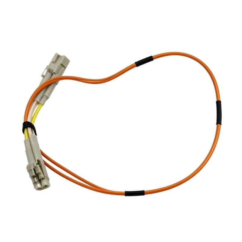
The Foxboro P0972VG Fiber Optic Cable is a short optical jumper designed for compatible industrial control network installations within the Foxboro I/A Series distributed control system (DCS) environment. With a cable length of 0.5 meters, this component is intended for short-distance optical connections between compatible network interfaces and related control system equipment.
In industrial automation, communication cabling is an essential part of the overall control architecture. Controllers, network switches, communication interfaces, and distributed control equipment depend on suitable physical connections to exchange information. Fiber optic cabling transmits data through optical signals rather than electrical signals, making it useful in installations where electrical isolation and resistance to electromagnetic interference are important considerations.
The P0972VG is identified as an orange, 0.5-meter LC fiber optic cable for the B Bus in supported Foxboro control network configurations. Its compact length is suitable for connections within control cabinets, network enclosures, and other installations where compatible optical ports are located close together.
Unlike an active communication module, this cable does not process data, execute control logic, or require an independent power supply. Its function is to provide the physical optical path between compatible devices. Reliable operation therefore depends on connector compatibility, the optical characteristics of the cable, proper installation, and the requirements of the connected network equipment.
For industrial maintenance teams, the P0972VG can be relevant when replacing a damaged jumper, restoring an existing optical connection, or maintaining the original cabling arrangement in a Foxboro I/A Series installation. Before ordering, engineers should verify the complete part number, connector type, cable length, and intended network connection.
Technical Specifications
| Parameter | Specification |
|---|---|
| Brand | Foxboro |
| Product Model | P0972VG |
| Product Type | Fiber Optic Cable / Optical Jumper |
| Cable Length | 0.5 m |
| Connector Type | LC-LC |
| Cable Color | Orange |
| Network Application | Foxboro I/A Series control network |
| Bus Identification | B Bus in supported configurations |
| Transmission Medium | Optical fiber |
| Electrical Power Requirement | None; passive cable assembly |
| Primary Function | Optical signal transmission between compatible interfaces |
| Dimensions | Cable assembly; length 0.5 m |
| Shipping Weight | 3 kg, as provided |
| Typical Installation | Control cabinets and industrial network enclosures |
Note: Confirm the actual cable construction, connector polish, fiber type, and network compatibility against the installed equipment documentation. The 3 kg figure is the supplied shipping weight and should not be treated as the cable’s net weight.
Function and Working Principle
The Foxboro P0972VG provides the physical connection needed for optical communication between compatible network interfaces. Its operation is based on the transmission of light through optical fiber.
1. Optical Signal Transmission
An optical communication interface converts electrical data into optical signals. The signals travel through the fiber and are converted back into electrical data by the receiving interface.
The P0972VG provides the optical path between the connected interfaces. It does not independently generate, process, or interpret the transmitted information.
2. Short-Distance Network Connectivity
With a length of 0.5 meters, the cable is intended for short connections where equipment is installed close together. This can help maintain an organized network layout inside control cabinets and equipment enclosures.
Selecting the correct cable length helps avoid excessive slack, unnecessary bends, and interference with adjacent wiring. The cable should not be stretched or forced into a routing path that exceeds its permitted bend radius.
3. Electrical Isolation
Fiber optic communication transfers information through light rather than through a conductive signal path. Consequently, the optical link does not create the same direct electrical connection between endpoints as a copper signal cable.
This characteristic can be useful in industrial environments where ground-potential differences and electrical noise are concerns. However, fiber optic cabling does not replace protective grounding or other electrical safety measures required for the connected equipment.
4. Electromagnetic Interference Resistance
Optical fiber is inherently resistant to electromagnetic interference affecting the transmitted optical signal. This makes it useful around industrial drives, power equipment, switching devices, and other potential sources of electrical noise.
Overall system performance still depends on the connected interfaces, proper cable routing, connector cleanliness, and correct network configuration.
5. Network Bus Identification
The P0972VG is identified in Foxboro I/A Series cabling documentation as an orange, 0.5-meter LC fiber cable associated with the B Bus in supported configurations.
Where a control system uses redundant communication paths, correct cable identification is important. Connecting a cable to the wrong port or bus may prevent the intended network topology from operating correctly.
Role in Industrial Control Systems
The P0972VG can support the physical communication infrastructure of a distributed control system. Although it is a small component, its condition and correct installation can affect communication between connected network devices.
1. Foxboro I/A Series DCS Connectivity
Foxboro I/A Series installations use a combination of controllers, communication equipment, network infrastructure, and field interface components. Compatible fiber optic jumpers provide the physical connections required by the network design.
The P0972VG should be used only where the connected equipment supports the specified cable and connector arrangement.
2. Redundant Network Architecture
Industrial control networks may use redundant communication paths to improve availability. In such arrangements, separate network paths can allow the system to maintain communication when a supported path or component fails.
The P0972VG is identified with the B Bus in applicable cabling configurations. Correct cable placement is therefore important when maintaining the original network design.
The cable itself does not provide redundancy. Network redundancy depends on the complete architecture, supported interfaces, configuration, and functioning communication equipment.
3. Control Cabinet Interconnections
The compact cable length is useful for short connections between compatible optical ports inside a cabinet or enclosure.
Proper routing helps technicians identify network paths, maintain access to other components, and reduce the likelihood of accidental disconnection during maintenance.
4. Maintenance and Fault Restoration
When a fiber link fails, the cause may include connector contamination, cable damage, excessive bending, a faulty optical port, or an unrelated network problem.
Replacing a suspected defective jumper with a verified compatible cable can help isolate the fault. The cable should be inspected and tested as part of a systematic troubleshooting process rather than assuming that every communication alarm is caused by the cable.
Industrial Applications
1. Distributed Control Systems
The P0972VG is relevant to compatible Foxboro I/A Series DCS network installations. It can provide a short optical connection between supported network interfaces where the specified LC cable is required.
DCS communication infrastructure is important in applications that require coordinated monitoring and control across multiple process areas.
2. Oil and Gas Facilities
Oil and gas facilities use industrial control systems to monitor process conditions and coordinate equipment operation. Fiber optic connections may form part of the communication infrastructure within control rooms, equipment cabinets, and process facilities.
The P0972VG should be used only in network positions where its length, connector type, and optical characteristics match the installation requirements.
3. Chemical and Petrochemical Plants
Chemical and petrochemical facilities commonly use DCS architectures to supervise process variables, equipment status, and operating sequences.
Optical cabling can help provide communication paths in electrically noisy environments. Correct cable identification and maintenance are particularly important where communication failures could interrupt process monitoring.
4. Power Generation
Power generation facilities use industrial automation networks to connect control equipment, monitoring systems, and associated communication infrastructure.
A compatible optical jumper may be used for short internal connections in a supported Foxboro network configuration. Suitability must be confirmed against the actual control system design.
5. Industrial Network Cabinets
The 0.5-meter cable length makes the P0972VG suitable for short-distance connections inside cabinets and enclosures where the relevant optical interfaces are positioned close together.
A compact jumper can help keep the network installation organized while allowing technicians to access neighboring equipment for inspection and servicing.
Installation and System Integration
Correct installation is essential for maintaining optical signal quality and minimizing avoidable communication faults.
1. Verify the Part Number
Before installation, confirm that the cable is marked P0972VG and matches the required network connection.
Do not select a replacement based on color or length alone. Other Foxboro cable models may have different connector arrangements, lengths, or intended applications.
2. Check Connector Compatibility
The P0972VG is identified as an LC-LC cable assembly. Confirm that both connected interfaces use compatible LC optical ports and support the cable’s optical characteristics.
Connector compatibility includes more than physical fit. The fiber type, optical interface requirements, and connection topology must also be suitable.
3. Inspect the Cable Before Use
Check the cable jacket for cuts, crushing, kinks, and other visible damage. Inspect the connector housings for cracks, contamination, or mechanical wear.
A damaged cable or contaminated connector can cause excessive optical loss or intermittent communication.
4. Handle Fiber Connectors Carefully
Optical connector end faces are sensitive to dust, oil, and scratches. Keep protective caps in place until the cable is ready for connection, and use appropriate fiber-optic inspection and cleaning procedures.
Never look directly into an optical port or fiber end. Optical signals may be invisible to the human eye.
5. Maintain the Required Bend Radius
Avoid tight bends, sharp corners, excessive tension, and crushing by cabinet doors or cable ties. Follow the applicable cable manufacturer’s bend-radius requirements.
Improper routing can increase optical loss or cause permanent damage to the fiber.
6. Confirm the Network Path
Where the installation uses A Bus and B Bus connections, verify the designated port and bus assignment before connecting the cable.
Check that the cable is routed according to the system drawings and that the connected equipment is configured for the intended network architecture.
7. Verify Communication After Installation
After connecting the cable, inspect the relevant network indicators and diagnostic information. Confirm that the connected devices communicate as expected and that any applicable redundancy or network-health indicators show the intended status.
If a fault persists, inspect the connectors, confirm the cable model, and check the optical interfaces and network configuration before replacing additional components.
Compatible System Components
The P0972VG is a passive optical cable and must be paired with equipment that supports its connector and optical specifications.
| Component | Function | Compatibility Consideration |
|---|---|---|
| Foxboro I/A Series control network equipment | Provides the industrial communication infrastructure | Confirm the specific network architecture and supported interfaces |
| Compatible LC optical port | Provides the physical optical connection | Verify connector and optical-interface compatibility |
| Control network switch | Routes data between supported network devices | Confirm the switch type and intended cable connection |
| Controller or communication interface | Exchanges control and system information | Use only with interfaces documented for the cable |
| Redundant network interface | Supports a separate communication path where designed | Verify A Bus/B Bus assignments and network topology |
| Fiber optic inspection equipment | Helps identify connector contamination or damage | Use procedures appropriate for the installed connector type |
| Fiber optic cleaning tools | Removes contamination from connector end faces | Use compatible cleaning materials and follow safe handling practices |
The table identifies possible system-level components rather than items included with the cable. The exact compatible equipment depends on the specific Foxboro installation.
Alternative Models and Replacement Considerations
When replacing the P0972VG, choose a cable based on the required optical interface and network function rather than selecting any cable with the same length.
| Related Cable Model | Documented Description | Replacement Consideration |
|---|---|---|
| P0972UN | 0.5 m LC fiber cable, identified with the A Bus in applicable configurations | May be relevant when the required connection is the corresponding A Bus path; confirm all specifications |
| P0972VG | 0.5 m LC fiber cable, orange, identified with the B Bus in applicable configurations | Reference model for this listing |
| P0972UJ | 1.0 m LC-to-LC fiber cable | Different length; verify the network use and optical characteristics |
| P0972TN | 3 m LC fiber cable | Longer cable; confirm the specific network connection and installation requirements |
| P0972TP | 15 m LC fiber cable | Intended for a longer connection where supported by the network design |
These related models are not automatically interchangeable. Confirm fiber type, connector compatibility, intended network use, routing requirements, and the system documentation before substituting another cable.
Key Advantages
Compact 0.5-Meter Length
The short length supports organized connections between nearby optical interfaces, helping reduce unnecessary cable slack in cabinets and enclosures.
Optical Signal Transmission
The cable provides an optical communication path for compatible industrial network equipment without using a conductive data path between the optical endpoints.
Resistance to Electromagnetic Interference
Fiber optic transmission is not susceptible to electromagnetic interference in the same way as electrical signal transmission over copper conductors.
Support for Foxboro Network Maintenance
The P0972VG part number provides a specific reference for maintenance teams working with compatible Foxboro I/A Series network configurations.
Clear Bus Identification
The orange color and documented B Bus association help technicians identify the intended cable in installations that use the corresponding cabling arrangement.
Passive Operation
The cable does not require an independent power supply or active signal processing. Its role is to provide the physical connection between compatible optical interfaces.
Technical FAQs
1. What is the Foxboro P0972VG?
The P0972VG is a 0.5-meter fiber optic jumper cable used in compatible Foxboro I/A Series control network installations.
2. What is the cable length?
The specified cable length is 0.5 meters.
3. What connector type does it use?
The P0972VG is documented as an LC-LC fiber optic cable. Verify the connector and optical specifications of the actual unit before installation.
4. What is the purpose of the orange cable?
Foxboro I/A Series cabling documentation identifies the orange P0972VG as a 0.5-meter cable for the B Bus in supported network configurations. Follow the system drawings when connecting it.
5. Does the P0972VG require power?
No. It is a passive cable assembly and does not require a separate electrical power supply.
6. Can it be used with any LC fiber optic port?
No. The connector may fit physically, but the cable must also match the port’s optical requirements, fiber type, and intended network application.
7. Can the P0972VG replace the P0972UN?
Not automatically. Both are documented as 0.5-meter LC fiber cables, but they are associated with different bus identification in applicable configurations. Confirm the intended A Bus or B Bus connection and all relevant specifications before substitution.
8. What should be checked if communication fails after installation?
Inspect the connector end faces, verify the cable model and port assignment, check for tight bends or physical damage, and review the network device diagnostics. If necessary, use suitable fiber-optic test equipment to investigate optical loss.
9. What is the shipping weight?
The supplied shipping weight for this listing is 3 kg. This should be treated as a shipping or packaged weight, not the net weight of the 0.5-meter cable itself.
10. What should buyers confirm before ordering?
Verify the P0972VG part number, 0.5-meter length, LC-LC connectors, intended network connection, cable condition, and packaging details. For critical control systems, confirm the replacement against the original equipment documentation.
Procurement and Maintenance Recommendations
When purchasing the Foxboro P0972VG Fiber Optic Cable, verify the exact part number and intended connection within the existing control network. The 0.5-meter length and LC-LC connector arrangement should be checked against the installed cable and network drawings.
For replacement projects, confirm whether the required connection belongs to the A Bus or B Bus and ensure that the optical characteristics match the connected equipment. A cable that fits the port may still be unsuitable if its fiber specifications or network application differ.
For surplus or previously installed cables, inspect the outer jacket, connector housings, and end faces. Where the cable’s condition is uncertain, appropriate optical testing can help determine whether it is suitable for service.
During maintenance, keep connectors capped when disconnected, follow approved cleaning procedures, and avoid bending or crushing the fiber. Label both ends where practical to make future troubleshooting easier.
For logistics, the supplied 3 kg shipping weight should be confirmed with the actual packaging. The cable’s physical length is 0.5 meters, but its packaged dimensions and shipping weight may differ from the dimensions and weight of the cable alone.
Conclusion
The Foxboro P0972VG Fiber Optic Cable is a 0.5-meter LC-LC optical jumper used for compatible Foxboro I/A Series control network connections. Its documented orange color and B Bus association can help identify its intended role in supported network architectures.
As a passive component, the cable provides the physical optical path rather than performing active communication processing. Correct part identification, connector cleanliness, careful routing, and verification of the intended network connection are essential for dependable operation.
For industrial maintenance and spare-parts procurement, matching the P0972VG to the original system documentation helps reduce the risk of incorrect substitutions and supports the reliable operation of the wider control network.