

ProductPRODUCT
Featured products
Contact Us
- Emerson
- UT63 7004-1102 3130-0872
- Circuit Board
- USA
- 140 × 25 × 100 mm
- 0.35 kg
- Xiamen, China
- New & In Stock
- T/T, PayPal, Western Union
- 1 Year
- 1-3 Working Days
- DHL, UPS, TNT, FedEx and EMS.
- 24-Hour Service
- COO
- 5
Our advantage

Global Logistics
We have a 10-year logistics and express cooperation agreement, so our products can be shipped to any place in the world.

Brand new and original
Our products are imported in bulk from the place of origin. Because of the cooperative relationship, our products are all original and 100% new.

24-hour service
We provide 7*24 hours service to our customers. We will be there whenever you need us.

Price advantage
All our products are priced very favorably because we have our own warehouse and supply.
| Company Information | |||
| [email protected] | |||
| Mobile | +8615980777398 | ||
| +8615980777398 | |||
| 15980777398 |
Product Overview
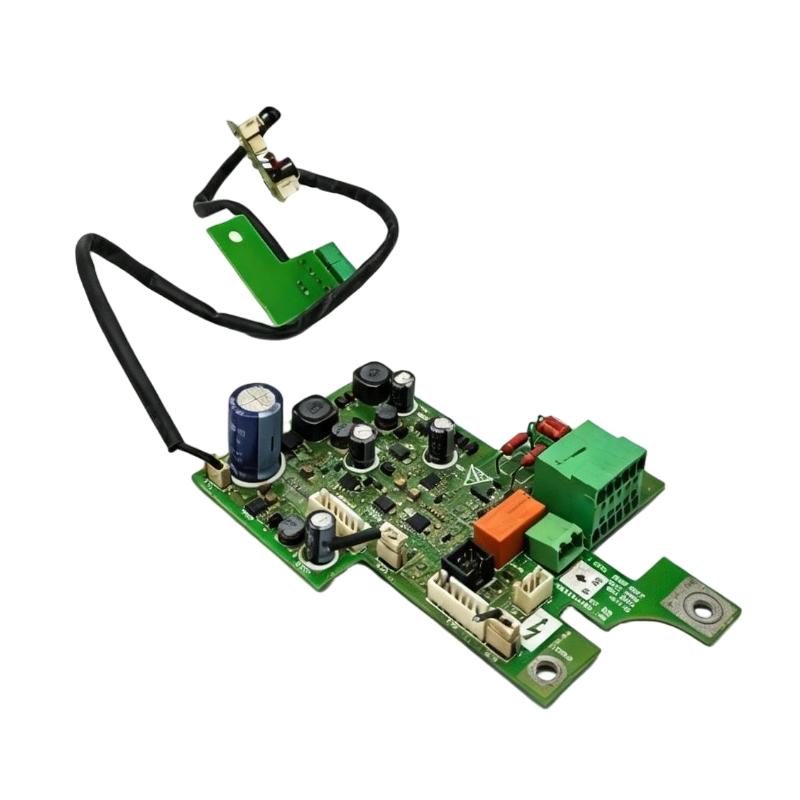
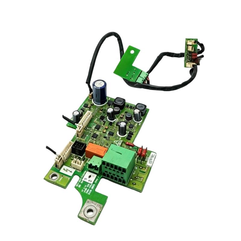
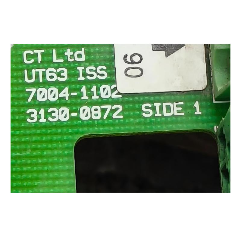
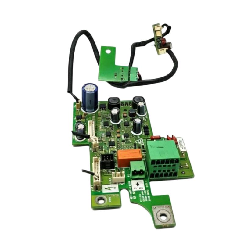
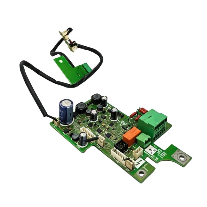
The Emerson UT63 7004-1102 3130-0872 Inverter Circuit Board is an electronic assembly associated with Control Techniques inverter equipment. The UT63 designation and the identifiers 7004-1102 and 3130-0872 are important when identifying the board for maintenance or replacement.
In industrial drive systems, circuit boards form part of the electronics responsible for operating the equipment. Depending on the board’s position within the drive, electronic assemblies may support power conversion, signal processing, control functions or communication between internal sections. The UT63 board is identified as an inverter board, making correct part identification particularly important when servicing the associated equipment.
For maintenance engineers, replacing a circuit board requires attention to more than the product name. The board markings, revision identification, connector positions and mounting arrangement should match the original assembly. A board that looks similar may have a different circuit layout or connection configuration.
The UT63 7004-1102 3130-0872 is suited to part-specific replacement planning. Recording all three identifiers in maintenance records helps distinguish the assembly from other electronic boards used in industrial drive equipment.
Technical Specifications
| Parameter | Specification |
|---|---|
| Manufacturer | Emerson / Control Techniques |
| Model | UT63 |
| Primary Part Number | 7004-1102 |
| Secondary Part Number | 3130-0872 |
| Product Type | Inverter Circuit Board |
| Component Category | Industrial Electronic Board Assembly |
| Application | Industrial Inverter Equipment |
| Dimensions | 140 × 25 × 100 mm |
| Weight | 0.35 kg |
Product Features
- Part-specific identification: Uses the UT63 designation and two associated part references for component identification.
- Inverter board assembly: Serves as an electronic component within the associated inverter equipment.
- Industrial maintenance use: Supports board-level servicing and replacement of compatible equipment.
- Revision identification: Board markings help technicians distinguish the installed hardware configuration.
- Connector-based integration: Electrical connections must follow the original equipment arrangement.
- Equipment-level compatibility: Replacement selection depends on matching the original board and its installed configuration.
- Maintenance traceability: Recording the complete part identification helps preserve service and inventory records.
Working Principle
An inverter system converts electrical power into an output suitable for operating an electric motor. Electronic circuit boards form part of the control and power-conversion architecture, with individual boards carrying out functions according to their circuit design and position within the equipment.
The UT63 is identified as an inverter circuit board. Its practical role in maintenance is considered within the electronic assembly of the associated drive equipment rather than as a standalone motor controller.
During normal drive operation, electronic circuitry works alongside the power stage, control inputs and other internal assemblies. These sections must operate together for the drive to respond correctly to operating commands and manage the connected motor.
When a drive develops a fault, technicians should evaluate the complete system before replacing the board. Supply conditions, external wiring, connected equipment and the drive’s fault indications can all help narrow down the cause. If the board is identified as the faulty component, its part numbers and revision markings should be checked before a replacement is installed.
Role in an Industrial Inverter System
The UT63 circuit board belongs to the electronic side of an inverter installation. Its replacement must be considered alongside the drive assembly, electrical connections and the equipment’s control and power sections.
Electrical Supply → Inverter Power Stage → Motor Output → Industrial Motor
Drive Electronics → Internal Circuit Board Assembly → Drive Control and Operating Functions
| System Component | Function | Relationship to the Circuit Board |
|---|---|---|
| Industrial Inverter | Converts electrical power into controlled motor output | Houses the electronic and power-conversion assemblies |
| UT63 Circuit Board | Electronic board assembly | Identified by the UT63, 7004-1102 and 3130-0872 markings |
| Inverter Power Stage | Switches electrical power to generate motor output | Operates as part of the inverter’s power-conversion system |
| Internal Control Electronics | Processes control functions within the drive | Coordinates relevant operating functions |
| Electrical Connectors | Link internal assemblies and external circuits | Must match the original board configuration |
| Motor Power Connections | Carry output power to the motor | Form part of the drive’s electrical output path |
| Control Wiring | Carries operating commands and status signals | Supports interaction between the drive and the wider system |
| Protective Earth | Provides the required protective grounding path | Must remain correctly connected during maintenance |
| Diagnostic Functions | Display faults and operating status | Help technicians assess drive condition during troubleshooting |
Industrial Applications
The UT63 is relevant to maintenance work involving inverter equipment that uses this board assembly. Typical work focuses on identifying the affected component, diagnosing drive faults and restoring the equipment to its intended operating condition.
| Application | Equipment Context | Role of the Circuit Board |
|---|---|---|
| Industrial Drive Maintenance | Inverter-equipped machinery | Supports board-level maintenance of the associated drive |
| Manufacturing Equipment Repair | Motor-driven production machinery | Forms part of the inverter electronics |
| Conveyor System Maintenance | Electrically driven material-transfer equipment | Relevant when servicing compatible inverter equipment |
| Process Machinery | Motor-driven industrial processes | Supports maintenance of the installed electronic assembly |
| Drive Fault Diagnosis | Inverters displaying faults or abnormal behavior | May be inspected when troubleshooting identifies a board-level issue |
| Electronic Board Replacement | Equipment requiring replacement of an internal circuit board | Requires matching the original part identification |
| Spare-Parts Management | Industrial maintenance inventory | Uses the complete part references for stock identification |
| Equipment Restoration | Repair of existing inverter installations | Supports replacement of the corresponding board assembly |
Installation and Maintenance
- Verify the board identification: Check the UT63 designation and both part references, 7004-1102 and 3130-0872.
- Identify the host inverter: Record the model and configuration of the equipment containing the original board.
- Review the fault history: Examine drive alarms, operating symptoms and maintenance records before replacing electronic components.
- Isolate the equipment: Disconnect the power supply and follow the drive’s safety procedure, including the specified DC-bus discharge and voltage-verification steps.
- Apply ESD precautions: Use suitable electrostatic-discharge protection when handling the circuit board.
- Inspect the original assembly: Examine the board markings, revision labels, connectors and visible condition.
- Compare the replacement: Match the part numbers and revision identification against the removed board.
- Check the connectors: Inspect mating connectors for contamination, damaged contacts or loose locking features.
- Preserve the original arrangement: Install the board using the specified mounting points and connection layout.
- Inspect surrounding components: Check adjacent wiring, mounting hardware and accessible connections for damage or displacement.
- Perform a controlled startup: Restore power according to the equipment procedure and check the drive’s status and operating response.
- Document the service work: Record the replaced board identification, observed fault, installation details and functional test results.
Compatible System Components
| Component | Function | Selection Consideration |
|---|---|---|
| Compatible Inverter Assembly | Houses the board and associated drive electronics | Match the board to the original equipment configuration |
| Matching UT63 Circuit Board | Replaces the corresponding electronic assembly | Check all part-number markings and revision information |
| Internal Electrical Connectors | Link the board to other assemblies | Preserve the original connection arrangement |
| Drive Power Stage | Converts electrical power for motor operation | Check the associated drive’s operating condition during diagnosis |
| Control Wiring | Carries operating and status signals | Inspect for loose connections and damaged conductors |
| Motor Power Cable | Connects the inverter to the motor | Check insulation, terminals and protective earth |
| Protective Grounding Connections | Provide the required electrical protection | Restore all grounding connections after servicing |
| Drive Diagnostic Interface | Provides fault and operating information | Review indications during troubleshooting and commissioning |
Recommended Related Models
| Model / Product | Product Type | Relationship | Selection Consideration |
|---|---|---|---|
| Emerson UT63 7004-1102 3130-0872 | Inverter Circuit Board | Exact requested board identification | Match all supplied identifiers |
| Control Techniques UT63 7004-1102 | Inverter Board | Related identification using the UT63 designation and primary part number | Check the secondary part reference and board markings |
| Emerson 7004-1102 | Circuit Board Part Reference | Primary part-number identification | Use together with the other board markings |
| Emerson 3130-0872 | Circuit Board Part Reference | Secondary part-number identification | Compare with the original board label |
| Compatible Control Techniques Inverter Assembly | Industrial Inverter | Equipment category associated with the board | Establish compatibility from the installed equipment and original board configuration |
Key Advantages
- Provides three identifiers for accurate board identification.
- Supports maintenance and replacement of industrial inverter electronics.
- Helps technicians maintain consistent spare-parts records.
- Allows the replacement to be checked against the original board configuration.
- Supports board-level troubleshooting within industrial drive equipment.
Technical FAQs
What do the UT63, 7004-1102 and 3130-0872 identifiers represent?
UT63 is the board designation, while 7004-1102 and 3130-0872 are associated part references. Recording all three helps identify the specific circuit board during maintenance and replacement.
What should be checked before fitting a replacement UT63 board?
Compare the part references, revision markings, connector arrangement and mounting points with the original assembly. The replacement must match the equipment’s required board configuration.
What should technicians investigate when an inverter develops a fault?
Review the drive’s fault indications, power supply, external wiring, motor connections and associated operating conditions. This helps determine whether the problem originates from the board or another part of the drive system.
Why should the original board revision be recorded during maintenance?
Revision information helps distinguish hardware configurations and maintain an accurate service history. Keeping this information with the part numbers also supports future replacement identification.