

ProductPRODUCT
Featured products
Contact Us
- Emerson
- SPMC2402
- Controlled Rectifier
- USA
- 399.1 × 298 × 310 mm
- 20 kg
- Xiamen, China
- New & In Stock
- T/T, PayPal, Western Union
- 1 Year
- 1-3 Working Days
- DHL, UPS, TNT, FedEx and EMS.
- 24-Hour Service
- COO
- 5
Our advantage

Global Logistics
We have a 10-year logistics and express cooperation agreement, so our products can be shipped to any place in the world.

Brand new and original
Our products are imported in bulk from the place of origin. Because of the cooperative relationship, our products are all original and 100% new.

24-hour service
We provide 7*24 hours service to our customers. We will be there whenever you need us.

Price advantage
All our products are priced very favorably because we have our own warehouse and supply.
| Company Information | |||
| [email protected] | |||
| Mobile | +8615980777398 | ||
| +8615980777398 | |||
| 15980777398 |
Product Overview
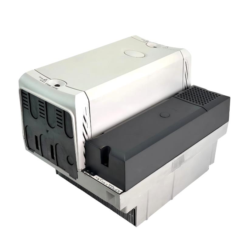
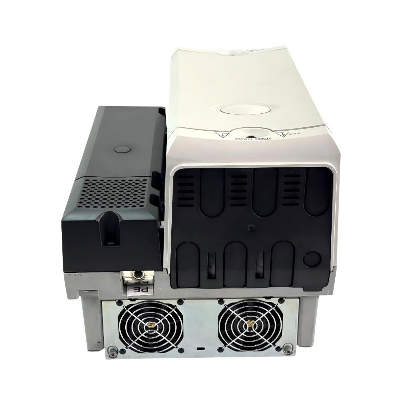
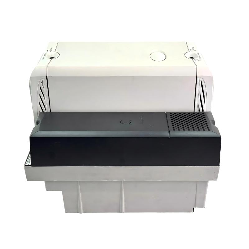
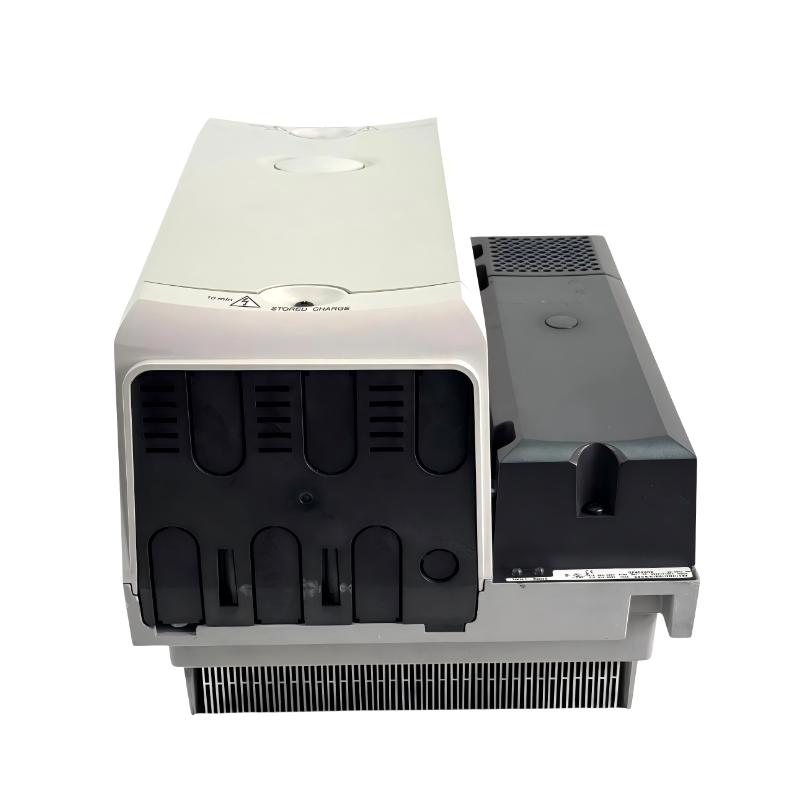
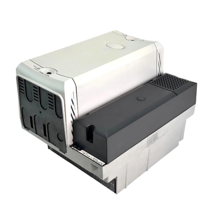
The Emerson SPMC2402 Unidrive SPM Controlled Rectifier is a controlled input rectifier module used in modular industrial drive systems. Unlike a conventional AC drive that directly controls a motor, the SPMC2402 converts three-phase AC power into a controlled DC supply for compatible inverter modules and drive arrangements sharing a common DC bus.
The SPMC2402 belongs to the 400 V class of the Unidrive SPM range and uses a dual half-controlled thyristor bridge configuration. Its two rectifier sections support installations with substantial DC power requirements, including multi-drive systems in which several inverter modules draw power from a shared DC bus.
A typical application is a production line with several coordinated motor axes. Instead of treating every axis as an entirely separate power-conversion system, engineers can use a common rectifier and DC-bus arrangement to supply compatible inverter modules. This requires careful calculation of the total load, supply characteristics, input reactance and DC-bus protection.
The SPMC2402 also incorporates a soft-start function. An external 24 V DC control supply is required for the rectifier’s control circuitry, and the installation must include the specified protection and fault-interlocking arrangements. These details matter during system design because the rectifier is part of the drive power architecture rather than an independent motor controller.
Technical Specifications
| Parameter | Specification |
|---|---|
| Manufacturer | Emerson / Control Techniques |
| Model / Part Number | SPMC2402 |
| Product Family | Unidrive SPM |
| Product Type | Controlled Rectifier |
| Rectifier Topology | Dual half-controlled SCR/thyristor bridge |
| Voltage Class | 400 V |
| AC Supply Voltage | 380–480 V AC |
| Input Supply | Three-phase AC |
| Rectifier Stages | Dual |
| AC Line Current | 677 A |
| DC Link Current | 758 A |
| Soft-Start Function | Integrated |
| Control Power Supply | External 24 V DC |
| Control Supply Current Requirement | 3 A |
| Application | DC-bus supply for compatible inverter modules and drive systems |
| Dimensions | 399.1 × 298 × 310 mm |
| Weight | 20 kg |
Product Features
- Controlled thyristor rectification: Uses a half-controlled SCR bridge to regulate the rectification process.
- Dual rectifier configuration: Supports high-power drive architectures requiring two rectifier sections.
- 400 V supply class: Matches compatible three-phase AC systems operating within the specified voltage range.
- Integrated soft start: Limits the initial charging demand through the rectifier’s built-in starting arrangement.
- Shared DC-bus operation: Supplies compatible inverter modules within a properly engineered drive system.
- External control supply: Uses a separate 24 V DC supply for the rectifier control circuitry.
- Status monitoring: Provides rectifier status information for integration with the drive control and fault-management system.
- System-level scalability: Can be incorporated into multi-inverter arrangements when the rectifier, bus connections and associated components are correctly rated.
Working Principle
The SPMC2402 receives three-phase AC power through its input connections. Its controlled thyristor bridges rectify the incoming supply to produce DC power for the connected drive system. By controlling the thyristor conduction process, the rectifier manages the DC-bus charging and supply behavior required by the installation.
The integrated soft-start function is particularly relevant when energizing a large DC bus. In a system containing multiple inverter modules, the DC-link capacitors can create a substantial initial charging demand. The rectifier’s starting arrangement helps manage this process without relying on the same external resistor-and-contactor soft-start arrangement required by an uncontrolled rectifier installation.
Once the DC bus is established, compatible inverter modules use that supply to generate the variable electrical output required by their connected motors. Each inverter handles its own motor-control task, while the SPMC2402 provides the common rectifier stage.
For example, a production line may have several conveyor drives and positioning axes operating from a shared power architecture. The rectifier supplies the common DC link, while the individual inverters regulate motor speed and torque. Correct operation depends on the combined electrical load, appropriate input line reactance, DC-bus capacity and coordinated fault handling.
The SPMC2402 is not itself a servo drive or a complete regenerative front end. Its controlled rectifier function must be distinguished from the motor-control functions performed by downstream inverter modules.
Role in a Unidrive SPM Modular Drive System
The SPMC2402 serves as the input power-conversion stage of a modular drive installation. It supplies the DC link used by compatible inverter modules, which then control the connected motors.
Three-Phase AC Supply → Input Line Reactance → SPMC2402 Controlled Rectifier → DC Bus → Compatible Inverter Modules → Motors
| System Component | Function | Relationship to the SPMC2402 |
|---|---|---|
| Three-Phase AC Supply | Provides incoming electrical power | Supplies the rectifier input |
| Input Line Reactor | Provides the required input reactance | Must be selected according to the rectifier installation requirements |
| SPMC2402 Controlled Rectifier | Converts AC input power into controlled DC power | Establishes the DC supply for the drive system |
| DC-Bus Connections | Distribute DC power between compatible modules | Carry rectified power to the inverter stages |
| SPMD Inverter Module | Converts DC-bus power into controlled AC output | Controls the connected motor |
| Industrial Motors | Convert electrical power into mechanical motion | Execute the machine’s operating movements |
| External 24 V DC Supply | Powers the rectifier control circuitry | Supports control and status functions |
| Input Fuses | Protect the incoming power circuit | Must match the rectifier and installation requirements |
| DC-Bus Protection | Protects the shared DC power arrangement | Must account for the complete connected system |
| Control System or PLC | Coordinates machine operation and fault responses | Receives relevant status information and manages system interlocks |
| Output Sharing Choke, Where Required | Supports specified parallel inverter arrangements | Must be selected for the applicable inverter configuration |
Industrial Applications
| Application | Typical Equipment | Role of the SPMC2402 |
|---|---|---|
| Multi-Axis Production Lines | Coordinated conveyors and processing stations | Supplies the common DC bus for compatible inverter modules |
| Material Handling Systems | Large conveyor networks and transfer mechanisms | Supports a shared modular drive power architecture |
| Industrial Processing Machinery | Multiple motors operating in coordinated sequences | Provides rectified DC power to the inverter stages |
| Packaging Production Lines | Several synchronized servo or drive-controlled mechanisms | Supports a common power arrangement where compatible |
| High-Power Drive Installations | Modular inverter assemblies | Supplies the DC link for the connected inverter system |
| Multi-Motor Machinery | Machines with several independently controlled motors | Allows multiple compatible inverters to share a rectifier supply |
| Industrial Retrofit Projects | Existing Unidrive SPM installations | Replaces a matching rectifier after electrical and configuration checks |
| Specialized Power Systems | Custom-engineered drive cabinets | Serves as the controlled rectifier stage within the specified power architecture |
Installation and Maintenance
- Verify the rectifier model: Confirm that SPMC2402 matches the required voltage class, rectifier configuration and DC-bus requirements.
- Check the incoming supply: Verify that the three-phase AC supply is compatible with the 380–480 V operating class.
- Select the input line reactor: Install the required input reactance according to the rectifier configuration and applicable installation specifications.
- Isolate the power system: Disconnect the AC supply, isolate the DC bus and verify that stored energy has discharged to a safe level before servicing.
- Inspect the mounting arrangement: Ensure that the rectifier is securely installed and that the cabinet provides the required ventilation and clearance.
- Verify power connections: Check the AC input, DC output and protective earth connections against the installation wiring requirements.
- Check the control supply: Confirm the external 24 V DC supply, polarity, current capacity and specified fuse protection.
- Inspect DC-bus connections: Verify the bus connections, insulation, conductor sizing and compatibility with the connected inverter modules.
- Confirm fuse coordination: Check the specified semiconductor and circuit protection arrangements for the rectifier and complete drive system.
- Verify fault interlocking: Ensure that rectifier fault status is connected to the appropriate drive enable or shutdown logic so that downstream inverters are disabled when required.
- Perform a controlled startup test: Verify the control supply, status indications, DC-bus behavior and coordinated response of the connected inverter modules.
- Record maintenance findings: Document the rectifier model, protection configuration, control-supply condition, fault history and inspection results.
Compatible System Components
| Component | Function | Compatibility Consideration |
|---|---|---|
| Unidrive SPMD Inverter Module | Converts DC power into controlled motor output | Match voltage class, current rating and operating duty |
| SPMU2402 Uncontrolled Rectifier | Provides an alternative rectifier architecture | Compare control requirements, soft-start arrangement and application needs |
| SPMC1402 Controlled Rectifier | Provides a related single-rectifier configuration | Verify whether its capacity and topology meet the system requirements |
| INL412 Input Line Reactor | Provides input line reactance | Confirm the required reactor rating and installation arrangement |
| OTL Output Sharing Choke | Supports specified parallel inverter arrangements | Select according to the connected inverter configuration |
| External 24 V DC Power Supply | Supplies rectifier control power | Meet the required voltage, current and protection specifications |
| Semiconductor Fuses | Protect rectifier semiconductor components | Match the specified fuse class and current rating |
| DC-Bus Conductors and Connections | Distribute rectified power | Size according to the system current and installation requirements |
| Control Relay and Interlock Circuit | Transfers rectifier status into the drive control system | Ensure faults trigger the required shutdown response |
Recommended Related Models
| Model / Product | Product Type | Relationship | Selection Consideration |
|---|---|---|---|
| Emerson SPMC1402 | Unidrive SPM Controlled Rectifier | Related controlled rectifier with a single bridge configuration | Compare rectifier topology and required DC-bus capacity |
| Emerson SPMU2402 | Unidrive SPM Uncontrolled Rectifier | Dual uncontrolled rectifier alternative | Evaluate the soft-start arrangement and control requirements |
| Emerson SPMU1402 | Unidrive SPM Uncontrolled Rectifier | Related single uncontrolled rectifier | Check voltage class, topology and application requirements |
| Emerson SPMD14 Series | Unidrive SPM Inverter Module | Compatible inverter family for 400 V-class systems | Select the exact module according to motor current and operating duty |
| Emerson INL412 | Input Line Reactor | Related power-system component | Verify required input reactance and rectifier compatibility |
| Emerson OTL Output Sharing Choke Series | Output Sharing Choke | Used in specified parallel inverter arrangements | Match the choke to the inverter arrangement and current requirements |
Key Advantages
- Provides controlled rectification for compatible 400 V-class drive systems.
- Uses a dual half-controlled thyristor bridge configuration.
- Includes an integrated soft-start function.
- Supports common DC-bus architectures using compatible inverter modules.
- Provides status information for system-level fault monitoring and interlocking.
Technical FAQs
What is the difference between the SPMC2402 and SPMU2402?
The SPMC2402 uses controlled thyristor rectification and includes an integrated soft-start function. The SPMU2402 uses an uncontrolled diode rectifier and requires a different soft-start arrangement. The appropriate choice depends on the power architecture and control requirements.
Why is an input line reactor required for the SPMC2402?
The rectifier requires sufficient input reactance to keep the electrical conditions within the intended operating limits. An incorrectly selected or omitted reactor can cause excessive current and place additional stress on the rectifier and connected equipment.
Why must the rectifier fault output be connected to the inverter control system?
The rectifier supplies the common DC bus for downstream inverter modules. If the rectifier reports a fault, the system must respond appropriately to prevent the inverters from continuing to operate under an unsafe or unsupported power condition. The required shutdown and interlock behavior must be implemented in the control system.
Can the SPMC2402 directly control a motor?
No. The SPMC2402 performs the rectification and DC-bus supply function. A compatible inverter module is required to convert the DC-bus power into the controlled motor output needed for speed, torque or position regulation.