

ProductPRODUCT
Featured products
Contact Us
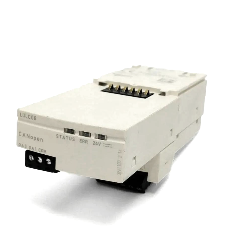
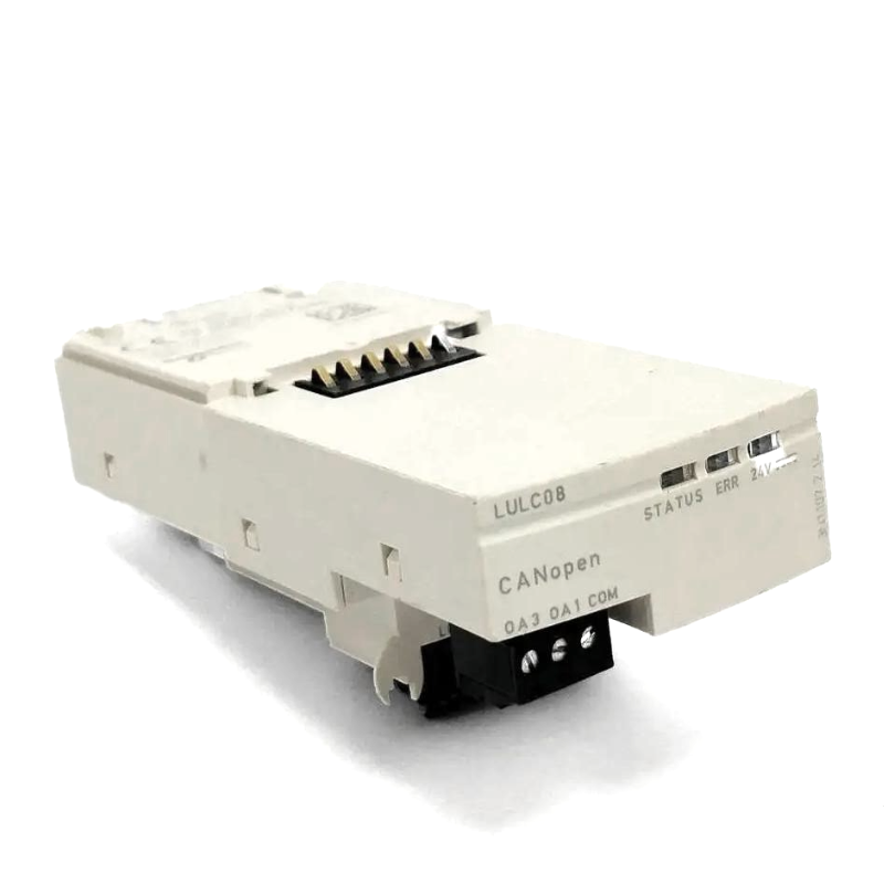
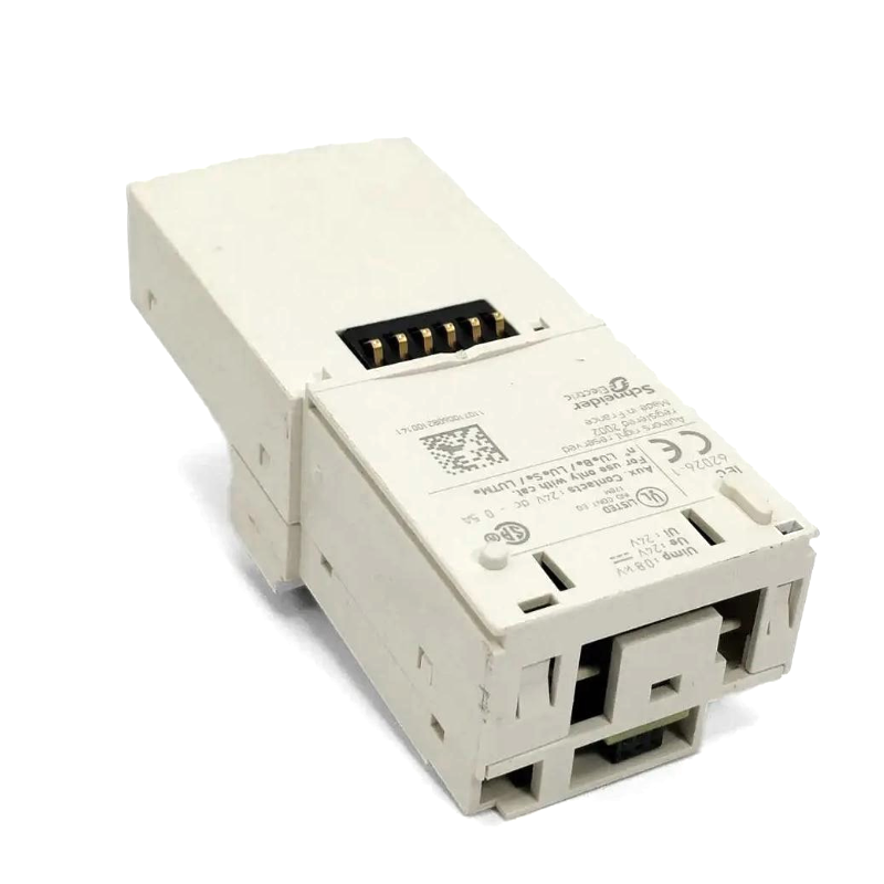
- Schneider
- LULC08
- CANopen Communication Module
- France
- 113 × 49 × 49 mm
- 0.104 kg
- Xiamen, China
- New & In Stock
- T/T, PayPal, Western Union
- 1 Year
- 1-3 Working Days
- DHL, UPS, TNT, FedEx and EMS.
- 24-Hour Service
- COO
- 5
Our advantage

Global Logistics
We have a 10-year logistics and express cooperation agreement, so our products can be shipped to any place in the world.

Brand new and original
Our products are imported in bulk from the place of origin. Because of the cooperative relationship, our products are all original and 100% new.

24-hour service
We provide 7*24 hours service to our customers. We will be there whenever you need us.

Price advantage
All our products are priced very favorably because we have our own warehouse and supply.
| Company Information | |||
| [email protected] | |||
| Mobile | +8615980777398 | ||
| +8615980777398 | |||
| 15980777398 |
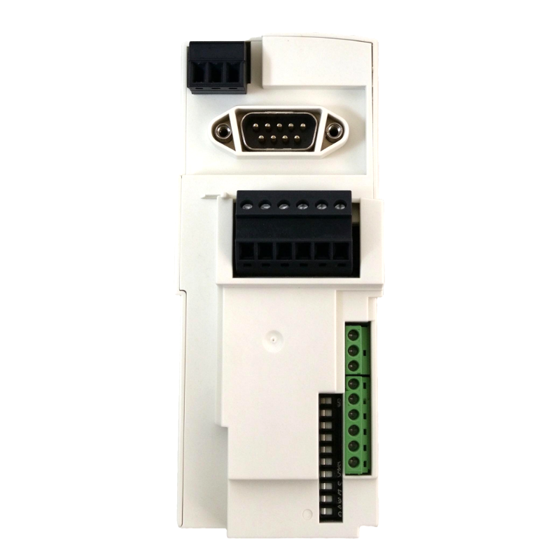
Product Overview
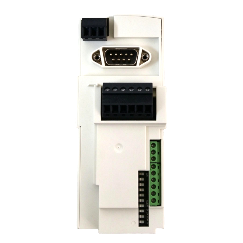
The Schneider LULC08 TeSys Ultra CANopen Communication Module connects compatible TeSys U motor starter-controllers to a CANopen industrial communication network. Installed on the front of the starter assembly, it allows motor-control information and operating commands to be exchanged between the starter and a supervisory controller, such as a PLC.
In a machine-control cabinet, the LULC08 can help integrate motor starters into a networked automation architecture. Instead of relying exclusively on individual hardwired control signals, the controller can communicate with supported starter functions over the CANopen bus. This is useful in packaging machinery, conveyor systems, pumping installations and production equipment containing multiple motor-driven mechanisms.
The module includes a nine-pin male SUB-D connector for CANopen communication, two configurable inputs for binary sensors and a 24 V DC output rated at 0.5 A for local auxiliary control. It also provides LED indications for module status, faults and the relevant 24 V output supply condition.
The LULC08 is a communication accessory for the TeSys U starter system rather than a standalone motor starter. Its operation depends on the compatible power base, control unit, external 24 V DC supply and correctly configured CANopen network. When selecting a replacement, engineers should check the installed control unit, hardware version, network wiring and application configuration.
Technical Specifications
| Parameter | Specification |
|---|---|
| Manufacturer | Schneider Electric |
| Model / Part Number | LULC08 |
| Product Family | TeSys Ultra / TeSys U |
| Product Type | CANopen Communication Module |
| Device Application | Communication |
| Mounting Location | Front side of compatible motor starter |
| Mounting Type | Plug-in |
| Communication Protocol | CANopen |
| Network Connector | 9-pin male SUB-D |
| External Supply Voltage | 24 V DC |
| External Supply Operating Range | 20–28 V DC |
| Configurable Digital Inputs | 2 |
| Input Type | Resistive |
| Auxiliary Output Voltage | 24 V DC |
| Auxiliary Output Current | 0.5 A |
| Output Functions | Local auxiliary command and starter-control connections |
| Local Signaling | Module status, fault and 24 V supply LEDs |
| Compatible Equipment | TeSys U starter-controller with compatible power base and control unit |
| Operating Temperature | -25 to +55°C |
| Storage Temperature | -40 to +85°C |
| Protection Rating | IP20 |
| Dimensions | 113 × 49 × 49 mm |
| Weight | 0.104 kg |
Product Features
- CANopen network communication: Connects compatible TeSys U starter-controllers to a CANopen control network.
- Plug-in installation: Mounts on the front of a compatible starter assembly.
- Nine-pin SUB-D connector: Provides the physical interface for the CANopen bus.
- Two configurable inputs: Accepts binary sensor signals for supported applications.
- 24 V DC auxiliary output: Supplies up to 0.5 A for the specified local auxiliary command function.
- LED diagnostics: Provides visual indications of module status, faults and the relevant supply condition.
- Starter-control integration: Works with a compatible power base and control unit to support networked motor management.
- Network data exchange: Supports communication functions configured through the CANopen architecture.
- Modular maintenance: Allows the communication accessory to be handled separately from the other components of the starter assembly.
Working Principle
The LULC08 operates as the communication interface between a compatible TeSys U starter-controller and a CANopen network. Once installed and supplied with the required power, it exchanges supported control and status data with the network master according to the configured communication parameters.
A PLC can use the network to issue supported commands and read information from the starter-controller. Depending on the control unit and configuration, this may include operating status, fault information and motor-management data. The module communicates these values; the actual switching and protection functions remain dependent on the connected starter and control unit.
For example, a production line may contain several conveyor motors controlled by TeSys U starter assemblies. A PLC connected through CANopen can coordinate the conveyor sequence, monitor starter status and respond to reported faults. The LULC08 provides the communication path for the compatible starter, reducing the need to implement every status and command as a separate hardwired signal.
The two configurable inputs can be used for supported binary sensor functions, while the 24 V DC auxiliary output supplies the specified local command function. Their use must follow the module’s wiring requirements and the connected starter configuration.
Communication faults may arise from incorrect node addressing, wiring errors, missing bus termination or incompatible device configuration. During commissioning, the network should be checked alongside the module’s LED indications and the operating status of the connected starter-controller.
Role in a TeSys U CANopen Motor-Control System
The LULC08 provides the communication layer between the starter assembly and the machine controller. It enables compatible TeSys U equipment to participate in a coordinated automation system while the power base and control unit perform their respective motor-control and protection functions.
PLC / CANopen Master → CANopen Bus → LULC08 Communication Module → TeSys U Control Unit and Power Base → Motor
| System Component | Function | Relationship to the LULC08 |
|---|---|---|
| LULC08 Communication Module | Exchanges supported control and status data | Provides the CANopen interface |
| PLC / CANopen Master | Executes machine logic and coordinates equipment | Sends commands and reads network data |
| TeSys U Power Base | Switches power to the connected motor | Performs the power-switching function |
| TeSys U Control Unit | Provides starter control and applicable protection functions | Works with the communication module as part of the starter assembly |
| CANopen Network Cable | Carries bus communication signals | Connects the module to the network |
| 24 V DC External Supply | Supplies the module’s external power circuit | Powers the specified module functions |
| Binary Sensors | Detect machine states or process conditions | Can connect to the module’s configurable inputs where supported |
| Motor Contactor / Starter Mechanism | Connects or disconnects the motor supply | Operates as part of the TeSys U starter assembly |
| Engineering Software | Configures network devices and communication parameters | Supports CANopen network commissioning |
| Operator HMI | Displays machine status and alarms | Receives relevant information through the PLC or supervisory system |
Industrial Applications
| Application | Typical Equipment | Role of the LULC08 |
|---|---|---|
| Packaging Machinery | Conveyors, feeders and packaging stations | Connects compatible motor starters to the machine’s CANopen network |
| Conveyor Systems | Transfer belts and sorting equipment | Supports centralized starter monitoring and command exchange |
| Pumping Installations | Industrial pumps and utility-water systems | Integrates compatible starters into the supervisory control architecture |
| Material Handling | Transfer mechanisms and production-line drives | Exchanges supported motor-control information with the PLC |
| Manufacturing Lines | Multiple motor-driven production stations | Enables network communication with compatible TeSys U starters |
| Food and Beverage Equipment | Processing and packaging machinery | Supports networked motor control within the machine architecture |
| Industrial Utilities | Auxiliary motors and service equipment | Provides CANopen connectivity for compatible starter assemblies |
| OEM Control Panels | Distributed motor starter assemblies | Reduces dependence on individual hardwired signals for supported functions |
Installation and Maintenance
- Verify the module reference: Confirm that LULC08 is the required CANopen version rather than a TeSys communication module using another protocol.
- Check starter compatibility: Confirm that the installed power base and control unit support the LULC08, including any applicable control-unit version requirements.
- Isolate the equipment: Disconnect the relevant power sources and follow the machine’s electrical isolation procedure before installing or removing the module.
- Inspect the mounting interface: Check the starter assembly for damage, contamination or obstructions before fitting the communication module.
- Install the module correctly: Fit the LULC08 into the designated front mounting position according to the applicable installation instructions.
- Connect the external supply: Provide the specified 24 V DC supply within the permitted operating range and observe the correct polarity.
- Wire the CANopen bus: Connect the nine-pin SUB-D interface using the correct bus cable and connector arrangement.
- Configure the network: Set the required communication parameters and verify the node configuration within the CANopen master project.
- Check bus termination and topology: Confirm that the network layout, cable arrangement and termination follow the applicable CANopen installation requirements.
- Verify auxiliary I/O wiring: Check the two configurable inputs and 24 V DC output against the intended application and electrical ratings.
- Test communication and diagnostics: Check the module LEDs, network status and starter response during controlled commissioning.
- Record maintenance findings: Document the module reference, connected control unit, network configuration and any communication faults observed during servicing.
Compatible System Components
| Component | Function | Compatibility Consideration |
|---|---|---|
| TeSys U Power Base | Switches motor power | Match the power base to the starter assembly and motor requirements |
| TeSys U Control Unit | Controls starter operation and provides applicable protection functions | Verify compatibility with the LULC08 and the required hardware version |
| CANopen-Compatible PLC | Acts as the network master | Confirm support for the required CANopen configuration and device data |
| CANopen Bus Cable | Carries network communication signals | Select a suitable cable and connector arrangement |
| Nine-Pin SUB-D Connector | Connects the module to the CANopen network | Match the pin assignment and installation requirements |
| 24 V DC Power Supply | Supplies the module’s external power circuit | Meet the specified voltage range and current requirements |
| Binary Sensors | Supply discrete machine signals | Confirm signal compatibility with the module’s configurable inputs |
| Motor | Provides mechanical drive power | Match the starter and control-unit ratings to the motor |
| Ethernet / PLC Supervisory Network | Connects the PLC to the wider control system | Integrate through the selected PLC and network architecture |
| Operator HMI | Displays operating states and alarms | Obtain relevant data through the PLC or supervisory application |
Recommended Related Models
| Model / Product | Product Type | Relationship | Selection Consideration |
|---|---|---|---|
| Schneider LULC08 | TeSys U CANopen Communication Module | Requested communication module | Select for compatible TeSys U starter assemblies requiring CANopen |
| Schneider LULC07 | TeSys U Profibus DP Communication Module | Related communication module using PROFIBUS DP | Choose when the control network uses PROFIBUS DP |
| Schneider LULC09 | TeSys U DeviceNet Communication Module | Related communication module using DeviceNet | Verify the required network protocol before selection |
| Schneider LULC15 | TeSys U Advantys STB Communication Module | Related communication module for an Advantys STB architecture | Match the communication interface to the installed system |
| Schneider LU9BN11L | Pre-wired Connector | Related connection accessory for a compatible TeSys U power base | Check the power-base and coil connection arrangement |
| Schneider LU9MRL | Pre-wired Connector | Related connector accessory for a compatible TeSys U assembly | Verify the specific starter configuration before use |
Key Advantages
- Connects compatible TeSys U starter-controllers to a CANopen network.
- Provides a nine-pin SUB-D bus interface.
- Integrates two configurable inputs and a 24 V DC auxiliary output.
- Offers local LED indications for status and fault diagnosis.
- Supports modular installation within a compatible motor starter assembly.
Technical FAQs
What equipment is required to use the LULC08?
The module must be installed with a compatible TeSys U power base and control unit. The system also requires a suitable 24 V DC supply, CANopen network connection and a controller configured to communicate with the starter assembly.
How does the LULC08 differ from the LULC07?
The LULC08 is the CANopen communication version, whereas the LULC07 is intended for PROFIBUS DP networks. The appropriate model depends on the fieldbus used by the PLC and the existing network architecture.
What should be checked if the PLC cannot communicate with the starter?
Check the external supply, CANopen cable and connector, node configuration, network termination and controller communication settings. Also inspect the module’s LED indications and confirm that the connected control unit is compatible.
Can the LULC08 be used as a standalone motor starter?
No. The LULC08 is a communication module, not a power-switching device. It must be used with a compatible TeSys U starter assembly to provide the intended networked motor-control functions.