

ProductPRODUCT
Featured products
Contact Us
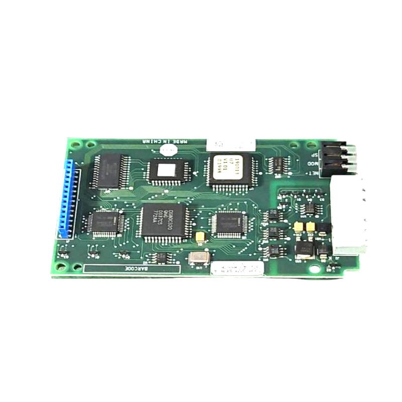
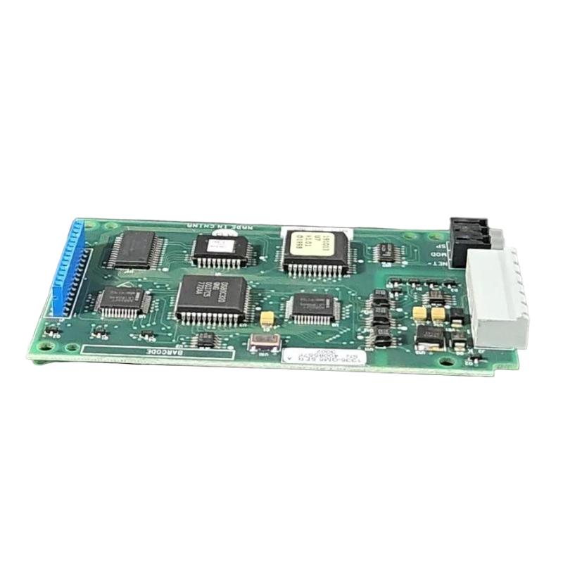
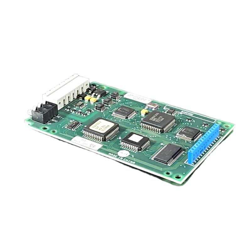
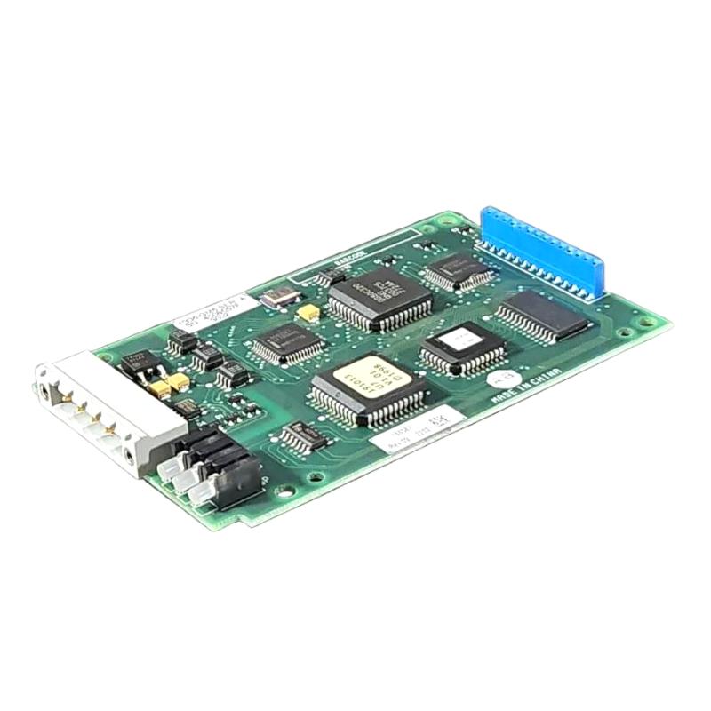
- Allen Bradley
- KALEX3 K688 94V-0
- Controller Board
- USA
- 150 × 100 × 30 mm
- 0.136 kg
- Xiamen, China
- New & In Stock
- T/T, PayPal, Western Union
- 1 Year
- 1-3 Working Days
- DHL, UPS, TNT, FedEx and EMS.
- 24-Hour Service
- COO
- 5
Our advantage

Global Logistics
We have a 10-year logistics and express cooperation agreement, so our products can be shipped to any place in the world.

Brand new and original
Our products are imported in bulk from the place of origin. Because of the cooperative relationship, our products are all original and 100% new.

24-hour service
We provide 7*24 hours service to our customers. We will be there whenever you need us.

Price advantage
All our products are priced very favorably because we have our own warehouse and supply.
| Company Information | |||
| [email protected] | |||
| Mobile | +8615980777398 | ||
| +8615980777398 | |||
| 15980777398 |
Product Overview
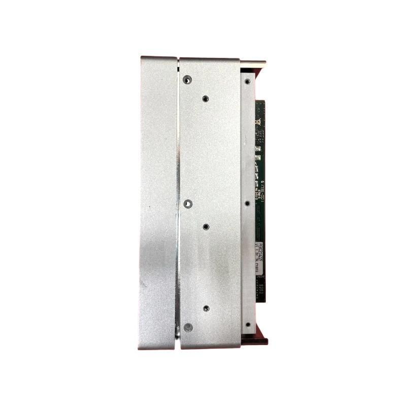
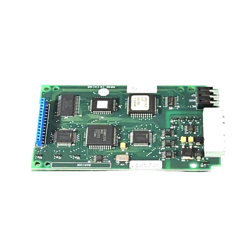
The Allen Bradley KALEX3 K688 94V-0 Controller Board is an industrial electronic board identified by its KALEX3 K688 marking and associated 94V-0 designation. In industrial automation equipment, controller boards support the electronic circuitry responsible for equipment operation, internal signal handling, and coordination between connected components. The board’s exact role depends on the equipment in which it is installed.
For maintenance engineers, identifying the board correctly is an important part of diagnosing electronic equipment faults. A controller board may be involved when a machine fails to start, internal signals are not processed as expected, or an existing assembly shows signs of electrical or component damage. Before replacing the board, technicians should compare its markings and circuit-board layout with the installed part and confirm the required replacement through equipment records.
The 94V-0 marking is associated with a flammability classification for printed circuit board materials. It should not be interpreted as a controller model number, operating-voltage rating, or indication of the board’s control functions. The KALEX3 K688 identification and the equipment manufacturer’s documentation are more relevant when determining the board’s intended application.
As a replacement component, the board must match the original assembly’s electrical connections, mounting arrangement, and functional requirements. Similar-looking controller boards are not necessarily interchangeable, even when their dimensions or printed markings appear comparable.
Technical Specifications
| Parameter | Specification |
|---|---|
| Brand | Allen Bradley |
| Model / Identification | KALEX3 K688 94V-0 |
| Product Type | Controller Board |
| Component Category | Industrial electronic circuit board |
| Board Identification | KALEX3 K688 |
| Marking | 94V-0 |
| Dimensions | 150 × 100 × 30 mm |
| Weight | 0.136 kg |
| Primary Function | Electronic control or signal-processing functions, depending on the host equipment |
| Installation Type | Installed within a compatible electronic equipment assembly |
| Typical Application | Industrial automation equipment maintenance and board replacement |
| Electrical Interface | Must be verified against the original assembly and applicable documentation |
| Compatibility | Equipment-specific; confirm the required board identification before installation |
| Maintenance Use | Fault diagnosis, replacement, and restoration of existing equipment |
Product Features
- Distinctive board identification: The KALEX3 K688 marking helps maintenance personnel identify the component and compare it with the board installed in the equipment.
- Controller-board construction: The assembly belongs to the industrial electronic board category, where circuit components and conductive paths support the host equipment’s electronic functions.
- 94V-0 material marking: This marking refers to a recognized flammability classification for applicable plastic materials, including printed circuit board substrates. It does not specify the board’s electrical performance.
- Equipment-specific functionality: The board’s actual role depends on its circuit design and the equipment in which it is installed. Its function should not be inferred from the marking alone.
- Replacement-part identification: The model and board markings give technicians reference information for checking spare-parts inventory and replacement requirements.
- Support for electronic equipment maintenance: A compatible replacement board can be used during troubleshooting or restoration when the original assembly has been identified as defective.
- Integration with existing assemblies: The board must work with the host equipment’s connectors, power arrangement, and associated circuitry.
- Visual inspection capability: Technicians can inspect the board for visible damage, such as burned areas, cracked solder joints, damaged connectors, or corrosion, where these are accessible.
- Controlled handling requirements: Appropriate electrostatic discharge precautions help protect sensitive electronic components during inspection, storage, and installation.
- Traceable maintenance records: Recording the installed board identification and replacement details helps support future troubleshooting and spare-parts management.
Working Principle
The Allen Bradley KALEX3 K688 94V-0 Controller Board operates as part of the electronic circuitry in its host equipment. When installed in the intended assembly, the board’s components and conductive paths support the electrical functions established by its circuit design.
Depending on the host equipment, a controller board may receive electrical inputs, condition or process signals, and pass information or control signals to other circuits. However, the specific inputs, outputs, processing functions, and communication methods of the KALEX3 K688 cannot be established from the printed identification alone.
A general electronic control path can be represented as:
Input signals or internal system data → Controller board circuitry → Associated electronic circuits or equipment functions
This sequence illustrates a common role for industrial controller boards, not a confirmed circuit-level description of this specific model. The actual signal flow depends on the equipment’s design.
During operation, the board’s electronic components work together according to the implemented circuit. A failure in a component, solder joint, connector, or conductive track may affect the equipment’s behavior. Symptoms can include intermittent operation, failure to power up, unexpected system responses, or loss of a particular function. These symptoms can also originate from other equipment components, so diagnosis should consider the complete assembly rather than assuming that the board is responsible.
When replacing the board, technicians should preserve the original connection arrangement and follow the equipment’s approved service procedure. After installation, the relevant equipment functions should be checked before the system is returned to normal operation.
Role in an Industrial Control Architecture
Within an industrial automation system, a controller board can form part of the electronic hardware that supports equipment-level control, internal signal processing, or communication between circuit assemblies. The KALEX3 K688 should be treated as an equipment-specific board until its precise function and host system have been established.
Unlike a complete programmable logic controller or standalone control module, a circuit board may rely on other assemblies for power, external connections, operator interfaces, or higher-level control. Its position in the architecture therefore depends on the equipment’s original design.
| Architecture Layer | Component or Function | Relationship to the Controller Board |
|---|---|---|
| Field equipment layer | Sensors, switches, and actuators | May provide inputs or respond to outputs handled by the host equipment |
| Signal interface layer | Input circuits, output circuits, and interface electronics | May exchange electrical signals with the board, depending on the circuit design |
| Equipment electronics layer | Controller boards and associated circuit assemblies | Provides the electronic functions implemented by the installed board |
| Main control layer | PLCs, controllers, or equipment control units | May coordinate overall operation or exchange signals with the equipment containing the board |
| Power distribution layer | Power supplies and internal power circuits | Supplies the required electrical power to the relevant assemblies |
| Maintenance layer | Wiring diagrams, service records, and replacement parts | Helps technicians identify the correct board and verify its installation |
The KALEX3 K688 should be assigned a specific architectural role only after the host equipment and circuit documentation have been identified. Its markings alone do not establish a particular PLC platform, communication protocol, or control-system family.
Industrial Applications
| Application | Potential Use of the Controller Board |
|---|---|
| Industrial automation equipment | May support electronic control functions within a compatible machine or equipment assembly |
| Equipment repair and refurbishment | Can be considered as a replacement component when the installed board has been identified as defective |
| Electronic control assemblies | May form part of the circuitry responsible for internal signal handling or equipment operation |
| Machine maintenance workshops | Provides a board-level identification reference for inspection and replacement work |
| Manufacturing equipment service | Supports restoration of the original electronic configuration when a matching replacement is required |
| Industrial equipment troubleshooting | Can be inspected when fault diagnosis points to a possible circuit-board problem |
| Spare-parts inventory management | Allows the KALEX3 K688 identification to be recorded for future maintenance requirements |
| Legacy equipment maintenance | May be relevant when servicing older equipment that uses this specific board assembly |
| Preventive maintenance programs | Can be included in board inspection and replacement records where the equipment service plan requires it |
| Electronic assembly inspection | Allows examination of accessible connectors, solder joints, circuit tracks, and components for visible damage |
| Control cabinet servicing | May be handled during maintenance of equipment electronics installed within a cabinet or enclosure |
| Equipment restoration projects | Supports the effort to retain the original circuit arrangement when a compatible board is available |
Installation and Maintenance
- Verify the board identification: Compare the KALEX3 K688 markings and 94V-0 designation with the original board and available equipment records. Do not rely solely on a similar appearance or a partial marking.
- Identify the host equipment: Establish the machine or electronic assembly in which the board is installed. The host equipment’s documentation is needed to confirm the board’s purpose and required replacement specification.
- Isolate the equipment before service: Follow the approved shutdown and electrical isolation procedure. Disconnect power as required and verify that stored electrical energy has been addressed before handling the board.
- Use electrostatic discharge precautions: Handle the board with suitable ESD protection and use an appropriate antistatic work surface and packaging. Avoid touching exposed contacts or component leads unnecessarily.
- Inspect the replacement board: Check for visible cracks, damaged connectors, bent contacts, corrosion, contamination, or other signs of handling or storage damage before installation.
- Record the original connections: Photograph or document connector positions, cable routing, and mounting details where permitted. This helps prevent incorrect reconnection during reassembly.
- Confirm connector and mounting compatibility: Compare the replacement with the original board’s connector layout, mounting points, and relevant identifying features. Do not modify connectors or mounting arrangements to force a suspected substitute to fit.
- Check the installation environment: Ensure the board will be installed in the intended enclosure or assembly. Consider contamination, moisture, vibration, temperature, and other environmental factors specified for the host equipment.
- Install without mechanical stress: Seat the board and its connectors carefully. Avoid bending the circuit board, applying excessive pressure, or allowing fasteners to contact areas not intended for mounting.
- Inspect associated wiring and connectors: Before restoring power, check for loose connections, damaged cables, displaced plugs, and signs of overheating in the surrounding assembly. Correct any identified issues according to the service procedure.
- Perform post-installation checks: Restore power only after the assembly has been checked and secured. Follow the equipment-specific commissioning or functional test procedure to confirm that the relevant functions operate as expected.
- Document the service work: Record the board identification, reason for replacement, inspection findings, and test results. Update maintenance records and spare-parts information to support future fault diagnosis.
Troubleshooting considerations: If the equipment remains faulty after a board replacement, verify the power supply, connector seating, associated wiring, and surrounding assemblies before concluding that the replacement board is defective. Where practical, use the host equipment’s service documentation and approved diagnostic procedures to isolate the fault.
Related Components
| Component | Function | Relationship to the Controller Board |
|---|---|---|
| Main control assembly | Coordinates equipment operation | May host or communicate with the controller board, depending on the equipment design |
| Power supply circuit | Provides operating power to electronic assemblies | Supplies the board with the power required by its circuit design |
| Input interface circuitry | Receives signals from switches, sensors, or other devices | May provide input signals to the board |
| Output interface circuitry | Drives or conditions signals for connected equipment | May receive signals from the board and pass them to downstream circuits |
| Connector assemblies | Establish electrical connections between circuit boards and wiring | Must match the board’s specified connection arrangement |
| Internal wiring harnesses | Carry power and signals between assemblies | Connect the board to other parts of the host equipment |
| Mounting hardware | Secures circuit boards within an enclosure | Maintains the board’s intended mechanical position |
| Cooling and enclosure components | Help maintain the required operating environment | Protect the board from unsuitable environmental conditions where applicable |
| Equipment diagnostic interface | Supports fault checking and service procedures | May be used to evaluate the host equipment after board replacement |
| Service documentation | Records board functions, wiring, and maintenance procedures | Helps establish the correct part number and installation requirements |
Recommended Related Models
| Model | Product Description | Relationship |
|---|---|---|
| Allen Bradley KALEX3 K688 94V-0 | Controller Board | Reference identification for the board specified in the product title |
| Allen Bradley controller boards for the same host equipment | Equipment-specific controller boards | Should be considered only after the host equipment and required board identification are confirmed |
| Allen Bradley interface boards for the same equipment family | Equipment-specific interface circuit boards | May be related at the assembly level but are not necessarily interchangeable with the controller board |
| Allen Bradley power supply boards for the same equipment family | Equipment-specific power circuit boards | May support the same host equipment while serving a different electrical function |
| Allen Bradley replacement electronic assemblies | Equipment-specific circuit assemblies | Require verification of the exact model, circuit function, and connection arrangement before substitution |
Key Advantages
- Clear identification: The KALEX3 K688 marking supports part identification during maintenance and replacement.
- Board-level servicing: Allows technicians to investigate electronic faults at the circuit-board assembly level.
- Compatibility-focused replacement: Encourages matching the original board to the host equipment rather than selecting a substitute by appearance.
- Support for equipment restoration: A correctly matched replacement can help restore the intended electronic configuration.
- Maintenance traceability: Recording board markings and service history helps organize future troubleshooting and spare-parts planning.
- Controlled installation: Standard ESD handling and inspection practices help reduce the risk of avoidable damage during service.
Technical FAQs
1. What is the Allen Bradley KALEX3 K688 94V-0 Controller Board?
It is an industrial electronic board identified by the KALEX3 K688 marking and 94V-0 designation. Its specific control or signal-processing function depends on the host equipment and circuit design.
2. What does the 94V-0 marking mean?
The 94V-0 marking is associated with a flammability classification for applicable plastic materials used in electrical and electronic products, including printed circuit board substrates. It is not a voltage rating and does not identify the board’s control function.
3. How can I confirm whether the KALEX3 K688 board is compatible with my equipment?
Compare the complete board markings with the installed part and check the host equipment’s parts list, wiring information, or service documentation. Connector layout, electrical requirements, mounting details, and board function should all be considered before installation.
4. What should I check if the equipment does not work after replacing the controller board?
Check that the board is correctly identified and installed, all connectors are seated properly, and the associated wiring and power supply are functioning as expected. Follow the equipment-specific diagnostic procedure to determine whether the problem lies with the board or another part of the assembly.