

ProductPRODUCT
Featured products
Contact Us
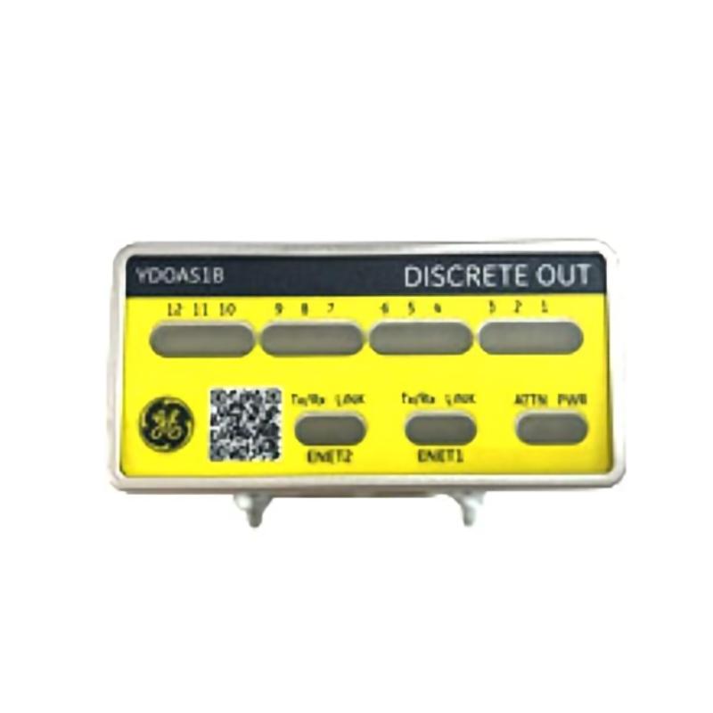
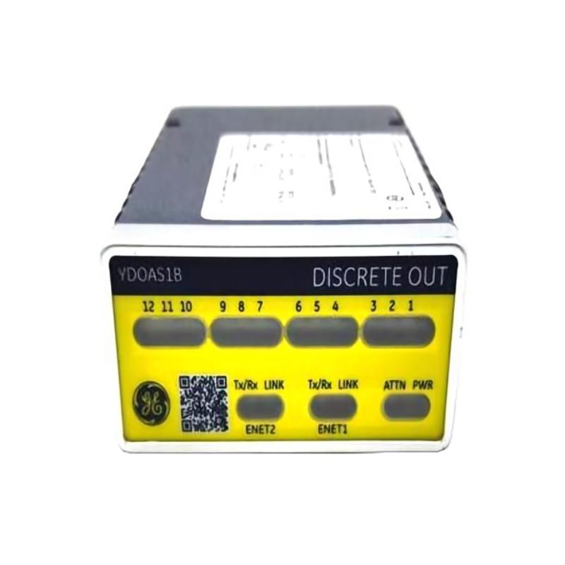
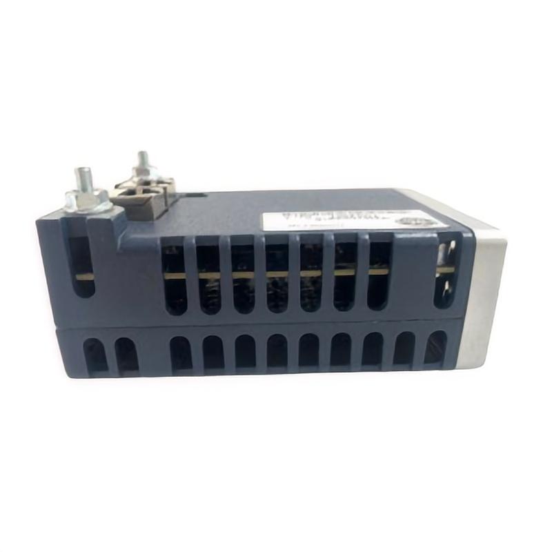
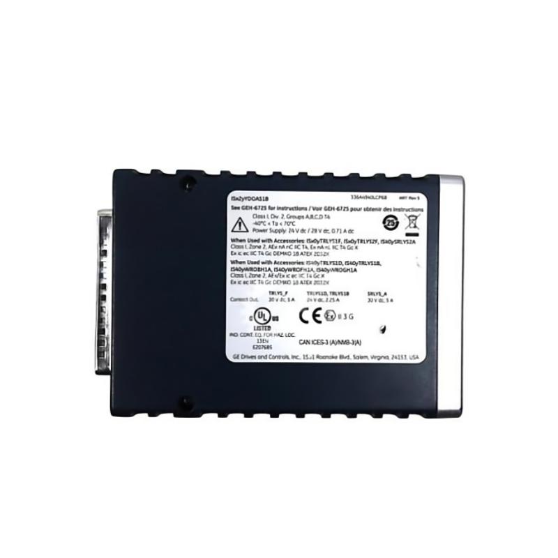
- GE
- IS420YDOAS1B
- Discrete Output Module
- USA
- 170 x 157 x 153 mm
- 1.2 kg
- Xiamen, China
- New & In Stock
- T/T, PayPal, Western Union
- 1 Year
- 1-3 Working Days
- DHL, UPS, TNT, FedEx and EMS.
- 24-Hour Service
- COO
- 4
Our advantage

Global Logistics
We have a 10-year logistics and express cooperation agreement, so our products can be shipped to any place in the world.

Brand new and original
Our products are imported in bulk from the place of origin. Because of the cooperative relationship, our products are all original and 100% new.

24-hour service
We provide 7*24 hours service to our customers. We will be there whenever you need us.

Price advantage
All our products are priced very favorably because we have our own warehouse and supply.
| Company Information | |||
| [email protected] | |||
| Mobile | +8615980777398 | ||
| +8615980777398 | |||
| 15980777398 |
Product Overview
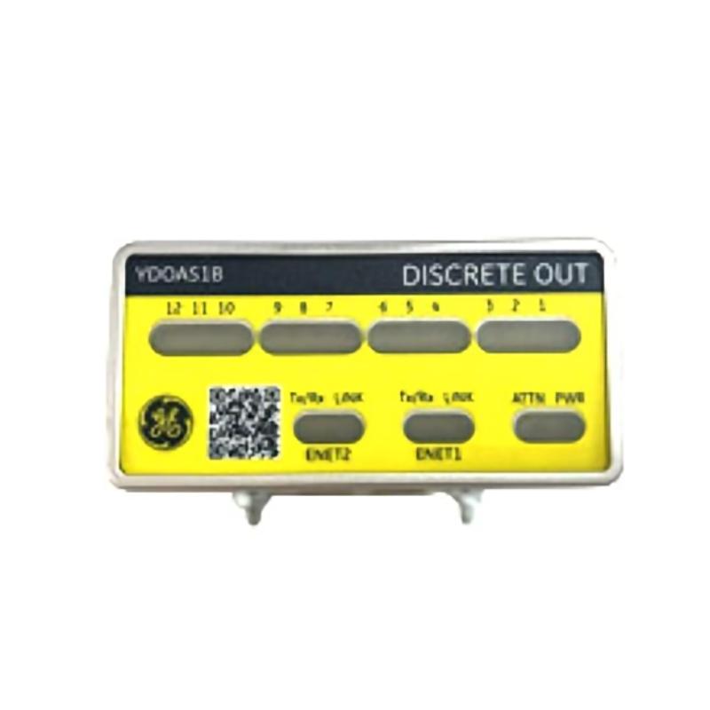
The GE IS420YDOAS1B Discrete Output Module is an industrial automation component intended for discrete signal output applications within compatible control system architectures. Discrete output hardware enables a controller to communicate control commands to external devices, supporting automated equipment operation, status indication, and coordinated process responses. In industrial environments, this type of module forms part of the interface between control logic and field-level equipment.
Discrete outputs are commonly used to represent defined states, such as ON/OFF commands, enable signals, operating requests, and alarm indications. Depending on the hardware design and system configuration, these signals may be used to control relays, contactors, solenoid valves, indicator lamps, and other compatible devices. The exact supported loads and electrical characteristics must be confirmed against the applicable hardware documentation before installation.
The IS420YDOAS1B is identified by the supplied model number as a discrete output module. Its role in an automation system is to help translate control decisions into output signals that can be acted upon by connected equipment. Correct integration requires attention to output circuit requirements, field wiring, load characteristics, system configuration, and operating conditions.
With supplied dimensions of 170 × 157 × 153 mm and a weight of 1.2 kg, the module’s physical characteristics should be considered when planning installation, cabinet layout, replacement work, and equipment handling. Before purchasing or commissioning the unit, technicians should verify the full part number, hardware revision, and compatibility with the intended host system.
Technical Specifications
| Parameter | Specification |
|---|---|
| Manufacturer | General Electric (GE) |
| Model Number | IS420YDOAS1B |
| Product Type | Discrete Output Module |
| Product Family | GE IS420 Industrial Control Hardware |
| Primary Function | Discrete control signal output |
| Signal Type | Discrete / digital output |
| Application | Industrial automation and control |
| Interface Role | Controller-to-field-device output interface |
| Dimensions | 170 × 157 × 153 mm |
| Weight | 1.2 kg |
| Installation | Compatible host equipment, subject to hardware verification |
| Output Channel Count | Confirm from the applicable product documentation |
| Output Voltage and Current Ratings | Confirm from the applicable product documentation |
| Output Circuit Type | Confirm from the applicable product documentation |
| Communication Interface | Confirm from the applicable product documentation |
| Operating Temperature | Confirm from the applicable product documentation |
| Compatible System | Verify against the installed control system and hardware revision |
The table distinguishes supplied identification and physical information from electrical specifications that require confirmation. Output voltage, current capacity, channel arrangement, isolation characteristics, and supported load types should not be assumed from the model designation alone.
What Is the GE IS420YDOAS1B?
The GE IS420YDOAS1B Discrete Output Module is an output-side component used in industrial control applications where discrete commands must be delivered to external circuits or devices. It supports the general function of output interfacing, allowing the control system to request a defined action in response to programmed logic, operator commands, process conditions, or equipment status.
In a typical automated process, a controller receives input information, evaluates the configured control logic, and determines whether an output should be activated or deactivated. The discrete output interface provides the appropriate electrical output behavior for the connected field circuit, subject to the module’s design and ratings.
A simplified control sequence is:
Process Condition → Input Acquisition → Control Logic → Discrete Output Module → Field Device → Process Response
The exact signal path depends on the host platform, associated interface hardware, and system architecture in which the module is installed.
Function and Working Principle
1. Receiving Output Commands
The control system determines the required output state based on application logic, process measurements, equipment status, or operator instructions. The command is then delivered through the relevant control architecture to the output interface.
2. Generating Discrete Signals
A discrete output represents a defined state rather than a continuously varying analog value. Depending on the module’s electrical design, an output channel may switch a compatible field circuit between specified states.
The precise switching method, voltage range, current limit, and electrical behavior must be checked before connecting a load.
3. Activating External Equipment
When configured and wired correctly, discrete outputs can be used in control schemes involving compatible field devices. Typical examples in industrial automation include relay interfaces, solenoid-operated equipment, indicator circuits, and equipment enable signals. Whether a particular device can be connected directly depends on the output rating and load requirements.
For inductive loads, such as relay coils or solenoids, suitable suppression and interface components may be necessary. The selection should follow the equipment manufacturer’s electrical and installation requirements.
4. Coordinating Automated Sequences
Discrete output commands are often part of larger operating sequences. For example, a controller may activate an output when permissive conditions are satisfied and deactivate it when a stop condition, interlock, or fault is detected.
The module provides the output interface, while the controller and application logic determine when the command should change state.
5. Supporting Equipment Status and Diagnostics
The control system may monitor commanded states, output status information, or associated diagnostic indications where the overall hardware architecture supports them. The availability and meaning of specific diagnostics should be confirmed for the installed module and controller configuration.
Role in Industrial Control Systems
Within an industrial automation system, a discrete output module helps connect control decisions with physical actions. It occupies the output stage of the control chain and works alongside controllers, input interfaces, communication hardware, terminal assemblies, power distribution, and field devices.
The general control architecture can be represented as:
Sensors and Inputs → Control Processor → Output Interface → Field Equipment
Each part has a distinct responsibility:
- Sensors and input modules: Provide information about process conditions and equipment states.
- Control processor: Executes application logic and determines the required output states.
- Discrete output module: Provides the appropriate output interface for compatible field circuits.
- Terminal and wiring assemblies: Connect the output circuits to external equipment.
- Field devices: Carry out the requested action, such as switching, indication, or actuation.
- Operator interface: Allows authorized personnel to observe system conditions and issue commands.
The IS420YDOAS1B should be selected as part of a verified system configuration rather than treated as a stand-alone replacement based only on its product category.
Industrial Applications
Discrete output interfaces are used across many sectors of industrial automation. The following examples describe common application categories for discrete output hardware; suitability for a specific installation depends on the module’s verified ratings and compatibility.
Industrial Machinery
Automated machinery uses discrete commands to coordinate equipment states, activate auxiliary circuits, and manage operating sequences. Output interfaces may form part of machine start, stop, enable, and status-indication functions.
Process Automation
Process facilities often use discrete signals to initiate equipment actions in response to controller logic. Examples may include requests to operate auxiliary equipment, switch process-related devices, or indicate a defined operating state.
Pumping and Fluid Handling
Discrete output circuits can be part of control arrangements for compatible pump auxiliaries, valves, and related equipment. Electrical load requirements, interlocks, and protective arrangements must be checked before connection.
Power Generation and Utilities
Industrial control systems in power generation and utility facilities use discrete commands for equipment coordination, status indication, and auxiliary control. A replacement module must match the requirements of the specific control platform and application.
Manufacturing and Material Handling
Conveyors, handling systems, and production equipment commonly rely on discrete signals for sequencing and equipment coordination. The output module’s role is to provide the required electrical interface for the connected circuits.
Alarm and Indication Systems
Discrete output states may be used to operate compatible indicator circuits or interface with alarm systems. Critical alarms and protective functions require appropriate system design, validation, and testing.
Installation and System Integration
Correct installation is essential for reliable output operation. Before installing or replacing the IS420YDOAS1B, confirm its identification and the requirements of the equipment in which it will be used.
Verify the Part Number and Revision
Record the complete model number and any hardware revision information marked on the installed unit. Compare these details with the replacement part and the host system’s approved hardware configuration.
Do not assume that a module with a similar appearance or product-family designation is electrically interchangeable.
Follow Electrical Safety Procedures
Before handling the module or changing field wiring, follow the site’s approved isolation and lockout/tagout procedures. Confirm that the relevant power sources have been safely isolated and that stored energy or externally supplied field circuits have been addressed.
Industrial output circuits may receive power from sources separate from the control electronics. Isolating one power source does not necessarily make every connected circuit safe.
Check Mounting and Physical Clearance
The supplied dimensions are 170 × 157 × 153 mm, and the listed weight is 1.2 kg. Check that the available installation space accommodates the unit, its connectors, wiring bend radius, required ventilation, and any manufacturer-specified clearance.
The physical dimensions should be confirmed against the actual hardware before preparing a mounting arrangement or replacement enclosure.
Verify Output Circuit Requirements
Before connecting field loads, determine the module’s supported output voltage, current rating, circuit type, and permitted load characteristics from the applicable documentation. Confirm that the external device is suitable for direct connection or requires an interposing relay or other interface.
Never connect a load based solely on the assumption that all discrete output modules share the same electrical characteristics.
Inspect Wiring and Terminations
Check terminal identification, conductor size, insulation condition, wire routing, and connection security. Keep field wiring organized and follow the installation requirements for the host system.
Where applicable, separate low-level signal wiring from high-power conductors to reduce the possibility of electrical interference or accidental wiring damage.
Configure the Control System
Confirm that the controller configuration recognizes the intended hardware and that the application logic maps the output commands to the correct channels. Any channel assignments, hardware definitions, or configuration parameters should match the approved system design.
Commission the Output Function
After installation, test the module under an approved commissioning procedure. Verify output states, field-device responses, interlocks, alarms, and recovery behavior. Confirm that the controlled equipment reaches the intended state when a command is activated or removed.
For machinery or processes with hazardous movement, pressure, temperature, or other risks, commissioning should include the required safety checks before returning the system to service.
Troubleshooting the GE IS420YDOAS1B
When a discrete output does not operate as expected, investigate the complete control path rather than immediately assuming that the module has failed. The problem may originate in the controller logic, configuration, field power, wiring, connected load, or output hardware.
1. Output Does Not Activate
Possible causes include:
- The controller has not issued the expected command.
- The application logic or an interlock prevents activation.
- The hardware configuration does not match the installed module.
- The output circuit lacks the required field power.
- Wiring or terminal connections are incorrect.
- The connected device or its interface has failed.
- The module has a hardware fault.
Recommended checks: Confirm the commanded state in the control system, review interlocks and permissives, inspect the relevant field circuit, and compare the wiring with the approved drawings. Check module diagnostics if supported by the installed system.
2. Output Remains Permanently Active
An output that appears to remain active may be caused by a persistent control command, an incorrect logic condition, a wiring fault, a short circuit, or a fault in the connected interface.
Recommended checks: Verify the actual command state, inspect the field circuit under safe isolation, and compare the observed behavior with the approved control sequence. Do not disconnect or reconnect energized conductors as a troubleshooting shortcut.
3. Connected Device Does Not Respond
The module may be issuing a valid command while the external device fails to operate. Potential causes include insufficient field power, an open circuit, incorrect load selection, a failed relay or actuator, or a mismatch between the output characteristics and the device requirements.
Recommended checks: Verify the device’s power supply, wiring continuity, load requirements, and interface arrangement. Confirm that the output is rated for the connected load before conducting electrical tests.
4. Intermittent Output Behavior
Intermittent operation may result from loose terminals, damaged wiring, vibration, unstable field power, electromagnetic interference, or an intermittent fault in the connected equipment.
Recommended checks: Review fault logs and event timestamps where available. Inspect wiring and terminations after isolating the relevant circuits. Examine whether the problem correlates with equipment movement, switching events, or changes in field power.
5. Controller Reports a Hardware or Configuration Fault
A reported hardware fault may relate to module identification, configuration mismatch, an installation issue, a connection problem, or a failed component.
Recommended checks: Record the exact diagnostic message, verify the complete part number and revision, inspect the installation, and compare the configured hardware with the actual equipment. Use the platform-specific diagnostic procedure to determine the appropriate next step.
6. Output Works During Testing but Fails in Operation
A module or field circuit may behave differently under actual operating conditions because of load characteristics, thermal conditions, vibration, supply variation, or changes in the control sequence.
Recommended checks: Compare the operating conditions with the module’s documented limits. Check the field device and interface components, and review system events to identify patterns. Avoid repeated resets or component substitutions without establishing the likely cause.
Maintenance Recommendations
A planned maintenance approach can help identify developing problems before they cause prolonged equipment downtime.
Inspect the Module and Connectors
Check the assembly for visible damage, contamination, corrosion, loose connectors, or signs of overheating. Any inspection requiring access to hazardous electrical areas should be performed only after the appropriate isolation procedure.
Review Wiring Condition
Inspect accessible wiring for abrasion, cracked insulation, loose terminations, moisture exposure, or mechanical strain. Verify that wiring labels remain readable and correspond to the current electrical drawings.
Monitor System Diagnostics
Where supported, review controller and hardware diagnostic records for recurring faults, abnormal status indications, or intermittent communication and configuration problems.
Check Connected Loads
A faulty field device can produce symptoms that resemble an output module failure. Periodically inspect the connected equipment and interface devices, and confirm that electrical loads remain within the approved limits.
Maintain a Replacement Record
Record the installed model, revision, location, configuration details, commissioning results, and any observed faults. Maintaining this information makes future replacement and fault diagnosis more efficient.
Store Spare Modules Correctly
Store replacement hardware in suitable protective packaging and within the environmental conditions specified by the manufacturer. Protect connectors and electronic assemblies from electrostatic discharge, moisture, contamination, and physical damage.
Compatible System Components
The IS420YDOAS1B may be used as part of a broader industrial control arrangement. The exact compatible components must be verified for the particular installation rather than inferred from the module’s product category.
| Component Category | Typical Role |
|---|---|
| Industrial Controller | Executes application logic and issues output commands |
| Discrete Input Hardware | Acquires equipment status and discrete field signals |
| Discrete Output Interface | Provides switching signals to compatible field circuits |
| Terminal or Wiring Assembly | Connects module circuits to field wiring |
| Interposing Relay | Provides an additional switching interface where required |
| Field Power Supply | Supplies the electrical power required by compatible loads |
| Operator Interface | Displays operating status and allows authorized commands |
| Engineering Software | Supports configuration, diagnostics, and maintenance where applicable |
| Field Devices | Perform the requested switching, actuation, or indication function |
This table describes functional component categories, not a confirmed compatibility list. Specific controller models, terminal assemblies, firmware versions, and accessories should be confirmed against the applicable GE hardware documentation and installed system configuration.
Replacement and Procurement Considerations
When sourcing a replacement GE IS420YDOAS1B Discrete Output Module, verify the identification details before placing an order.
Important checks include:
- Complete part number: IS420YDOAS1B
- Hardware revision and any suffix markings
- Product type and intended function
- Output voltage and current ratings
- Output circuit design and load compatibility
- Channel arrangement and terminal configuration
- Compatibility with the host controller and installed hardware
- Configuration and commissioning requirements
- Physical dimensions and mounting arrangement
- Condition, storage history, and supplier testing documentation
The supplied physical dimensions are 170 × 157 × 153 mm, and the listed weight is 1.2 kg. These values can support preliminary cabinet planning and shipping preparation, but should be confirmed against the physical unit when exact mechanical fit is required.
A replacement should not be selected solely because another module is described as a discrete output device. Different modules can have different electrical characteristics, connector arrangements, configuration requirements, and system compatibility.
Key Advantages
Discrete Output Interface
The module is intended for discrete output applications, supporting the connection between control commands and compatible field circuits.
Integration into Automated Control
When correctly matched to the host architecture, discrete output hardware allows programmed control logic to initiate equipment actions and coordinate operating sequences.
Support for Equipment Coordination
Discrete output signals can contribute to machine sequencing, auxiliary control, status indication, and other defined automation tasks.
Structured Fault Diagnosis
A systematic approach to controller logic, configuration, wiring, field power, and connected loads helps technicians distinguish between system-level problems and module-related faults.
Practical Replacement Planning
The supplied dimensions of 170 × 157 × 153 mm and weight of 1.2 kg provide useful information for preliminary handling, inventory, and installation planning.
Technical FAQs
What is the GE IS420YDOAS1B?
The GE IS420YDOAS1B is identified as a Discrete Output Module intended for industrial control applications involving discrete output signals.
What is the primary function of a discrete output module?
A discrete output module provides an interface through which a control system can issue defined electrical commands to compatible field circuits. The resulting action depends on the module’s electrical design, the connected device, and the application logic.
What are the dimensions of the IS420YDOAS1B?
The supplied dimensions are 170 × 157 × 153 mm.
How much does the IS420YDOAS1B weigh?
The supplied weight is 1.2 kg.
Which devices can be connected to the module?
Potential applications for discrete output hardware include compatible relay interfaces, indicator circuits, solenoid-operated equipment, and other discrete-control loads. The actual devices that can be connected directly must be determined from the module’s verified output ratings and wiring requirements.
How can an output failure be diagnosed?
Begin by checking the controller command, interlocks, hardware configuration, field power, wiring, connected load, and available diagnostic information. Replace the module only after other likely causes have been evaluated.
Is the IS420YDOAS1B interchangeable with another GE output module?
Interchangeability should not be assumed. Verify the full part number, revision, electrical specifications, terminal arrangement, and compatibility with the host system before replacement.
What information should be confirmed before installation?
Confirm the module’s electrical ratings, channel configuration, wiring requirements, environmental limits, and approved system compatibility. Follow the applicable installation and commissioning procedures for the specific equipment.
Conclusion
The GE IS420YDOAS1B Discrete Output Module is an industrial automation component intended to provide discrete output interfacing between control logic and compatible field circuits. Discrete output functions are important in automated machinery, process control, utility systems, and manufacturing environments where controllers must initiate defined equipment actions.
The supplied dimensions of 170 × 157 × 153 mm and weight of 1.2 kg provide useful information for installation planning, inventory management, and replacement logistics. Reliable operation depends on correct hardware identification, suitable electrical loading, accurate field wiring, appropriate controller configuration, and systematic commissioning.
For replacement or maintenance work, verify the complete IS420YDOAS1B part number and confirm the applicable electrical and system requirements before installation. Matching the module to the correct control architecture and checking the entire output circuit are essential steps toward dependable industrial automation performance.