

ProductPRODUCT
Featured products








Contact Us
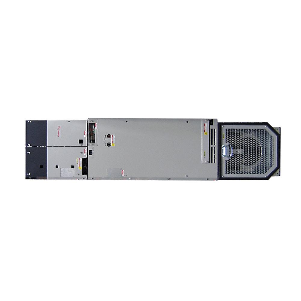
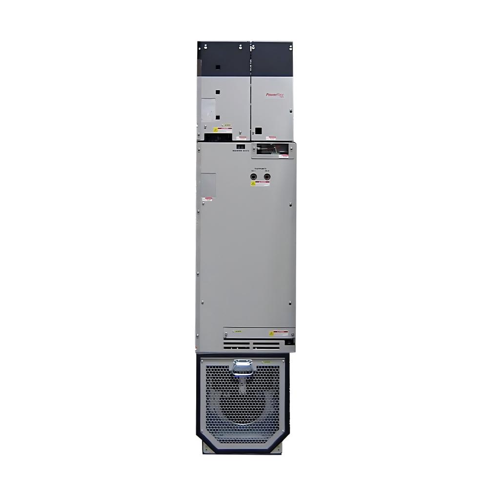
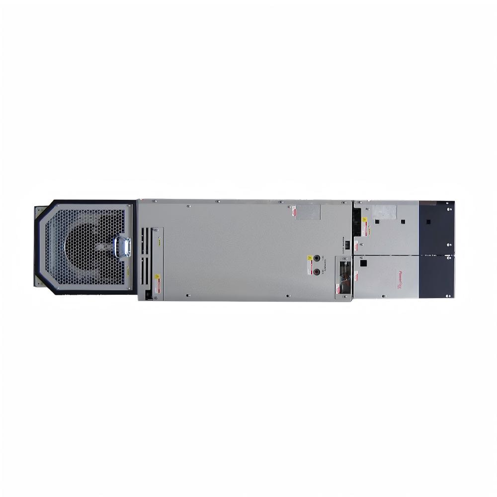
- Allen Bradley
- 20G14TE355JN0NNNNN
- PowerFlex AC Drive
- USA
- 600 × 600 × 2,400–2,500 mm
- 300kg
- Xiamen, China
- New & In Stock
- T/T, PayPal, Western Union
- 1 Year
- 1-3 Working Days
- DHL, UPS, TNT, FedEx and EMS.
- 24-Hour Service
- COO
- 37
Our advantage

Global Logistics
We have a 10-year logistics and express cooperation agreement, so our products can be shipped to any place in the world.

Brand new and original
Our products are imported in bulk from the place of origin. Because of the cooperative relationship, our products are all original and 100% new.

24-hour service
We provide 7*24 hours service to our customers. We will be there whenever you need us.

Price advantage
All our products are priced very favorably because we have our own warehouse and supply.
| Company Information | |||
| [email protected] | |||
| Mobile | +8615980777398 | ||
| +8615980777398 | |||
| 15980777398 |
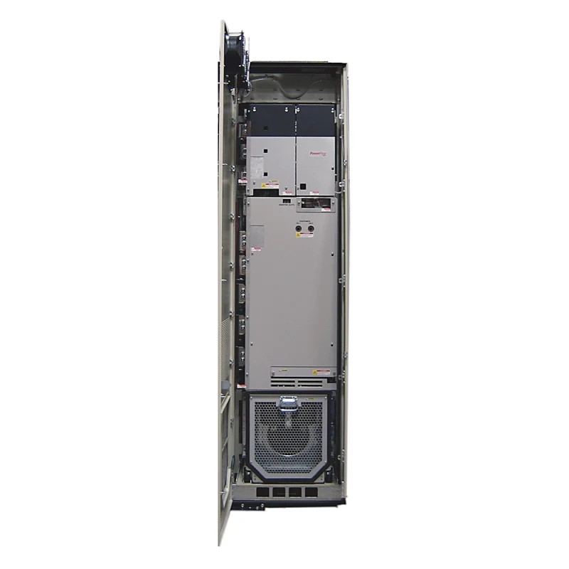
Allen-Bradley 20G14TE355JN0NNNNN – PowerFlex 755 High-Power AC Drive
1. Product Overview
The Allen-Bradley 20G14TE355JN0NNNNN is a high-power industrial variable frequency drive designed for controlling large three-phase AC motors. It belongs to the PowerFlex 755 drive platform and is intended for demanding industrial motor-control applications requiring high current capacity, adjustable speed, controlled acceleration, and reliable operation.
This model is designed for a 600 VAC, three-phase motor system and uses a DC input with precharge arrangement associated with an approximately 810 VDC nominal common-bus system. The drive converts DC bus energy into controlled three-phase AC output for the connected motor.
The unit has a 355 A base Normal-Duty rating and can support different motor capacities depending on whether it is applied in Light Duty, Normal Duty, or Heavy Duty service.
The drive is built on a Frame 8 platform and uses forced-air cooling. It is an open-type industrial drive intended for integration into suitable electrical cabinets and high-power drive systems.
The J configuration includes embedded EtherNet/IP communication, a filtered configuration, a CM jumper installed, no dynamic braking equipment, and a blank configuration without a local HIM.
2. Brand and Product Series
| Item | Specification |
|---|---|
| Brand | Allen-Bradley |
| Product Family | PowerFlex 750 Series |
| Product Series | PowerFlex 755 |
| Model | 20G14TE355JN0NNNNN |
| Product Type | High-Power Variable Frequency AC Drive |
| Drive Category | Industrial Motor Drive |
| Sub-Brand | PowerFlex 755 AC Packaged Drive |
| Input Architecture | DC Input with Precharge |
| Voltage Class | 600 VAC / 810 VDC Class |
| Output System | Three Phase |
| Frame Size | Frame 8 |
| Cooling Method | Forced Air |
| Enclosure Type | Open Type |
| Communication | Embedded EtherNet/IP |
| Filtering | Filtered |
| CM Jumper | Installed |
| Dynamic Braking | None |
| HIM Configuration | Blank / No HIM |
The PowerFlex 755 series is designed for industrial applications where motor operation forms an important part of a larger automation or production system.
The platform is particularly suitable for applications requiring communication capability, high motor capacity, flexible duty ratings, controlled acceleration, and integration with industrial automation equipment.
3. Main Technical Parameters
| Parameter | Specification |
|---|---|
| Model | 20G14TE355JN0NNNNN |
| Product Series | PowerFlex 755 |
| Product Family | PowerFlex 750 Series |
| Product Type | Variable Frequency AC Drive |
| Base Drive Current | 355 A |
| Input Type | DC Input with Precharge |
| Nominal DC Bus Class | Approximately 810 VDC |
| Motor Voltage Class | 600 VAC |
| Output Phase | Three Phase |
| Light-Duty Output Current | 395 A |
| Normal-Duty Output Current | 355 A |
| Heavy-Duty Output Current | 295 A |
| Light-Duty Motor Rating | Approximately 400 HP |
| Normal-Duty Motor Rating | Approximately 350 HP |
| Heavy-Duty Motor Rating | Approximately 300 HP |
| Frame | Frame 8 |
| Cooling Method | Forced Air |
| Enclosure | Open Type |
| Communication | Embedded EtherNet/IP |
| Filtering | Filtered |
| CM Jumper | Installed |
| Dynamic Braking | None |
| Operator Interface | Blank / No HIM |
| Installation | Industrial Cabinet / High-Power Drive System |
| Dimensions | Frame 8 configuration; exact dimensions depend on mechanical assembly |
| Approximate Dimensions | Approximately 600 × 600 × 2,400–2,500 mm class* |
| Approximate Weight | Approximately 275–300 kg* |
*The dimensions and weight shown above should be treated as planning-level values for the high-power Frame 8 configuration. The exact mechanical dimensions and final weight can vary according to the complete assembly, mounting arrangement, installed accessories, and mechanical configuration.
For cabinet construction, transportation, lifting, or replacement projects, the exact mechanical data for the complete installed unit should be confirmed before work begins.
4. Output Current and Duty Ratings
The 20G14TE355JN0NNNNN can be applied according to different duty classifications.
| Duty Category | Continuous Output Current | Approximate Motor Power |
|---|---|---|
| Light Duty | 395 A | 400 HP |
| Normal Duty | 355 A | 350 HP |
| Heavy Duty | 295 A | 300 HP |
The Light-Duty rating is generally suitable for applications with relatively low overload requirements, particularly variable-torque equipment such as centrifugal pumps and large fans.
The Normal-Duty rating provides a balanced operating capability for many general industrial applications.
The Heavy-Duty rating is intended for more demanding applications where higher torque or overload capability is required.
The drive should therefore be selected according to the actual motor current and application requirements rather than motor horsepower alone.
5. Product Introduction
The 20G14TE355JN0NNNNN is designed for large industrial motors that require more than simple fixed-speed operation.
In many industrial systems, the required speed of the driven machine changes according to production demand.
A pump may require different flow rates.
A fan may require different air volumes.
A conveyor may need controlled acceleration.
A compressor may require speed adjustment according to process conditions.
The drive controls the motor by generating a variable-frequency three-phase output.
By changing the output frequency and controlling the motor voltage, the drive allows the motor speed to be adjusted according to the operating requirements of the machine.
This makes the drive suitable for process control, mechanical protection, and energy-management applications.
6. DC Input with Precharge
One of the important features of this model is its DC input with precharge configuration.
The drive is intended for an approximately 810 VDC nominal common-bus architecture.
The DC bus supplies energy to the inverter section.
The inverter then generates controlled three-phase AC output for the motor.
The precharge arrangement is important because high-power drives contain substantial DC-link capacitance.
When a large DC capacitor system is energized, uncontrolled charging can result in significant inrush current.
A precharge system helps control the charging process before normal drive operation begins.
This type of configuration can be particularly useful in engineered multi-drive systems using a common DC bus.
7. Frame 8 Mechanical Design
The 20G14TE355JN0NNNNN uses a Frame 8 high-power mechanical platform.
This frame size is intended for large industrial installations and requires considerably more installation space than smaller machine-level VFDs.
The drive should be treated as a major electrical component within the overall system.
The installation design should consider:
- Electrical cabinet dimensions.
- Structural support.
- Floor loading.
- Mechanical mounting.
- Power-cable routing.
- Cooling airflow.
- Air intake and exhaust paths.
- Service clearance.
- Grounding.
- High-power terminal access.
- Lifting arrangements.
Because of its size and approximate 275–300 kg weight class, appropriate mechanical handling equipment should be considered during installation and replacement.
8. Dimensions and Weight
| Mechanical Parameter | Approximate Specification |
|---|---|
| Frame Size | Frame 8 |
| Enclosure | Open Type |
| Mounting Arrangement | Industrial Cabinet / Floor-Mounted System |
| Approximate Height | 2,400–2,500 mm class* |
| Approximate Width | 600 mm class* |
| Approximate Depth | 600 mm class* |
| Approximate Weight | 275–300 kg* |
| Cooling | Forced Air |
| Mechanical Handling | Lifting Equipment Recommended |
*These values are intended for planning purposes. The exact dimensions and weight should be checked against the complete mechanical configuration before cabinet fabrication, lifting, transportation, or installation.
High-power Frame 8 drives may require special installation equipment to assist with positioning, wiring, and cabinet integration.
9. Product Applications
9.1 Large Industrial Pumps
Large pumps are among the most common applications for a drive of this capacity.
Industrial pumping systems often operate under changing flow and pressure requirements.
Instead of running the motor continuously at maximum speed, the drive can adjust the motor speed according to process demand.
Typical pump applications include:
- Water-treatment systems.
- Wastewater facilities.
- Industrial process-water systems.
- Cooling-water circulation.
- Large circulation pumps.
- Chemical-processing pumps.
- Industrial pumping stations.
- Irrigation systems.
Controlled acceleration can also reduce sudden mechanical stress on the pump and associated pipework.
9.2 Large Industrial Fans
Industrial fans frequently operate under variable airflow requirements.
The drive can adjust motor speed according to ventilation or process requirements.
Typical applications include:
- Dust-collection systems.
- Process ventilation.
- Industrial exhaust.
- Furnace fans.
- Cooling systems.
- Cement facilities.
- Mining ventilation.
- Large air-handling systems.
Variable-torque fan applications are often suitable for Light-Duty operation when the motor current and process conditions are within the applicable limits.
9.3 Industrial Blowers
Large blowers often require adjustable speed to control airflow or pressure.
The drive can be used in systems involving:
- Process air.
- Aeration.
- Combustion air.
- Industrial ventilation.
- Pneumatic process systems.
Motor speed can be adjusted to follow changing process requirements.
9.4 Conveyors
Large conveyor systems can have considerable mechanical inertia.
Starting a large conveyor directly at full electrical supply can produce mechanical shock.
A variable-frequency drive can provide controlled acceleration and deceleration.
This can help reduce stress on:
- Conveyor belts.
- Gearboxes.
- Couplings.
- Shafts.
- Bearings.
- Conveyor structures.
For heavily loaded conveyors, the Heavy-Duty current rating should be considered carefully.
9.5 Compressors
Industrial compressors can require substantial motor power.
The drive can be used to adjust compressor speed according to production or process demand.
The exact suitability depends on the compressor design, torque requirements, and operating cycle.
9.6 Mixers and Agitators
Mixing and agitation systems can experience changing torque conditions.
Material viscosity and resistance may change during processing.
The drive provides adjustable speed control for suitable mixer and agitator applications.
Heavy-duty applications should be evaluated according to actual motor current and overload requirements.
9.7 Material-Handling Systems
The drive can also be used for high-power material-handling equipment.
Typical applications include:
- Bulk-material conveyors.
- Feed systems.
- Transfer systems.
- Processing machinery.
- Industrial transport equipment.
Controlled motor acceleration can help improve the mechanical operating conditions of large equipment.
10. Product Advantages
10.1 High Output Current Capacity
The 355 A Normal-Duty rating makes the drive suitable for large industrial motors.
The drive can support approximately 350 HP in Normal Duty and up to approximately 400 HP in Light Duty.
This provides substantial capacity for high-power industrial equipment.
10.2 Flexible Duty Ratings
The drive can be selected according to the mechanical requirements of the application.
| Duty Type | Output Current | Approximate Motor Rating |
|---|---|---|
| Light Duty | 395 A | 400 HP |
| Normal Duty | 355 A | 350 HP |
| Heavy Duty | 295 A | 300 HP |
A large fan and a heavily loaded conveyor may have similar motor horsepower but different overload requirements.
The flexible duty structure allows the drive to be matched more closely to the actual application.
10.3 Suitable for Common DC-Bus Systems
The DC-input architecture makes this model suitable for engineered common-bus drive systems.
Such systems may be useful where several large drives operate within a coordinated power-conversion arrangement.
The final design depends on the overall electrical architecture and the requirements of the complete drive system.
10.4 Controlled Motor Acceleration
The drive can provide controlled acceleration.
This can reduce sudden mechanical stress on large rotating equipment.
Benefits may include reduced stress on:
- Motors.
- Gearboxes.
- Couplings.
- Belts.
- Conveyor systems.
- Pump assemblies.
10.5 Adjustable Motor Speed
The drive allows motor speed to follow process demand.
This can improve control of:
- Flow.
- Pressure.
- Air volume.
- Conveyor speed.
- Production rates.
- Material movement.
10.6 Embedded Industrial Communication
The J configuration includes embedded EtherNet/IP communication.
This allows the drive to be integrated into an industrial automation network.
Typical functions can include:
- Run and stop control.
- Speed reference commands.
- Status monitoring.
- Fault indication.
- Diagnostic information.
- Process integration.
10.7 Forced-Air Cooling
The drive uses forced-air cooling to manage the heat generated by high-power electronic components.
Correct cabinet airflow is important for reliable operation.
Air intake and exhaust paths should remain clear.
10.8 Filtered Configuration
The drive includes a filtered configuration.
Correct grounding, cable routing, shielding, and separation of control and power wiring remain important for overall electrical performance.
11. Five Recommended Same-Series or Related Models
The following models are closely related to the 20G14TE355JN0NNNNN and are part of the same high-power PowerFlex 755 common-bus drive range.
| Model | LD Current | LD HP | ND Current | ND HP | HD Current | HD HP |
|---|---|---|---|---|---|---|
| 20G14TE295JN0NNNNN | 355 A | 350 HP | 295 A | 300 HP | 272 A | 250 HP |
| 20G14TE395JN0NNNNN | 435 A | 450 HP | 395 A | 400 HP | 329 A | 350 HP |
| 20G14TE435JN0NNNNN | 460 A | 500 HP | 435 A | 450 HP | 355 A | 350 HP |
| 20G14TE460JN0NNNNN | 510 A | 500 HP | 460 A | 500 HP | 395 A | 400 HP |
| 20G14TE510JN0NNNNN | 545 A | 550 HP | 510 A | 500 HP | 425 A | 450 HP |
The 20G14TE295JN0NNNNN is a suitable lower-capacity alternative when the application requires approximately 250–350 HP, depending on duty.
The 20G14TE395JN0NNNNN provides additional capacity for applications requiring approximately 400 HP in Normal Duty.
The 20G14TE435JN0NNNNN increases Normal-Duty capacity to approximately 450 HP.
The 20G14TE460JN0NNNNN and 20G14TE510JN0NNNNN are suitable for progressively larger high-power motor applications.
12. Comparison of Related Models
| Model | ND Current | ND HP | HD Current | HD HP | Relative Capacity |
|---|---|---|---|---|---|
| 20G14TE295JN0NNNNN | 295 A | 300 HP | 272 A | 250 HP | Lower |
| 20G14TE355JN0NNNNN | 355 A | 350 HP | 295 A | 300 HP | Reference Model |
| 20G14TE395JN0NNNNN | 395 A | 400 HP | 329 A | 350 HP | Higher |
| 20G14TE435JN0NNNNN | 435 A | 450 HP | 355 A | 350 HP | High |
| 20G14TE460JN0NNNNN | 460 A | 500 HP | 395 A | 400 HP | Very High |
| 20G14TE510JN0NNNNN | 510 A | 500 HP | 425 A | 450 HP | Maximum in This Group |
The 20G14TE355JN0NNNNN occupies an important position in this range.
It provides higher output capacity than the 295 A version while remaining below the larger 395 A, 435 A, 460 A, and 510 A versions.
13. Five Popular Related Models from the Same Brand
| Model | Series | Main Rating | Voltage Class | Typical Application |
|---|---|---|---|---|
| 20G11GD034AA0NNNNN | PowerFlex 755 | 34 A class | 480 VAC | Small industrial machinery |
| 20G11GD052AA0NNNNN | PowerFlex 755 | 52 A class | 480 VAC | Pumps and general machinery |
| 20G11GD077AA0NNNNN | PowerFlex 755 | 77 A class | 480 VAC | Medium industrial systems |
| 20G1ALE355JN0NNNNN | PowerFlex 755 | 355 A class | 600 VAC | High-power AC-input systems |
| 20G14TD740JN0NNNNN | PowerFlex 755 | 740 A class | High-power class | Very large industrial motors |
The smaller models are suitable for general industrial motor-control applications.
The 20G1ALE355JN0NNNNN has a similar output-current class but uses a different power-input configuration.
The 20G14TD740JN0NNNNN is intended for substantially larger high-power motor applications.
14. Application Selection Guide
| Application | Recommended Duty | Suitability |
|---|---|---|
| Large Centrifugal Pump | Light / Normal Duty | Excellent |
| Industrial Fan | Light Duty | Excellent |
| Process Blower | Light / Normal Duty | Excellent |
| Large Conveyor | Normal / Heavy Duty | Very Good |
| Compressor | Normal / Heavy Duty | Good |
| Mixer | Heavy Duty | Application Dependent |
| Industrial Ventilation | Light / Normal Duty | Excellent |
| Process Pump | Normal Duty | Excellent |
| Material Handling | Normal / Heavy Duty | Very Good |
| Production Machinery | Normal / Heavy Duty | Good |
The final selection should be based on motor full-load current, overload requirements, torque characteristics, acceleration time, and operating cycle.
15. Installation Considerations
A high-power Frame 8 drive requires careful installation planning.
| Installation Item | Main Requirement |
|---|---|
| DC Supply | Confirm compatibility with the DC input system |
| Motor Current | Verify against the selected duty rating |
| Motor Power | Confirm the HP requirement |
| Cabinet | Provide sufficient mechanical space |
| Cooling | Provide adequate forced airflow |
| Grounding | Use appropriate industrial grounding |
| Power Wiring | Select according to current and installation conditions |
| Control Wiring | Keep separate from high-power cables |
| Communication | Confirm EtherNet/IP requirements |
| Service Access | Provide sufficient maintenance clearance |
| Weight | Plan for approximately 275–300 kg |
| Lifting | Use appropriate mechanical equipment |
The drive should be installed as part of a complete electrical system.
The motor, power supply, DC bus, grounding system, protective equipment, and control network should all be considered together.
16. Cooling and Thermal Management
High-power variable-frequency drives generate substantial heat during operation.
The forced-air cooling system requires adequate airflow through the electrical installation.
The cabinet should be designed with attention to:
- Ambient temperature.
- Air intake.
- Air exhaust.
- Cabinet heat load.
- Air-filter condition.
- Fan performance.
- Maintenance access.
Restricted airflow can cause excessive internal temperature.
Regular inspection of the cooling system is therefore important for long-term operation.
17. Grounding and Electrical Installation
Proper grounding is essential in high-power drive installations.
The drive, motor, cabinet, and associated equipment should be connected using appropriate industrial grounding and bonding practices.
Control wiring should be separated from high-current power cables where practical.
Communication cables should also be routed according to industrial installation requirements.
Good installation practices can help reduce:
- Electrical interference.
- Communication disturbances.
- Control-system noise.
- Unexpected drive faults.
- Instrumentation problems.
18. Maintenance Considerations
Routine maintenance should include inspection of the cooling and electrical systems.
Important areas include:
- Cooling fans.
- Air filters.
- Air passages.
- Power connections.
- Grounding points.
- Motor cables.
- Cabinet temperature.
- Fault history.
Repeated drive faults should be investigated carefully.
A fault does not always indicate that the drive itself has failed.
The cause may be related to the motor, mechanical load, power supply, cooling system, cable installation, or application settings.
19. Main Advantages Summary
| Advantage | Description |
|---|---|
| High Output Capacity | 355 A Normal-Duty current |
| High Motor Capacity | Approximately 350 HP in Normal Duty |
| Light-Duty Capability | Approximately 400 HP |
| Heavy-Duty Capability | Approximately 300 HP |
| DC Input | Suitable for common DC-bus applications |
| Frame 8 Platform | Designed for high-power industrial installations |
| Forced-Air Cooling | Suitable for large electronic power systems |
| Embedded EtherNet/IP | Supports industrial network integration |
| Filtered Configuration | Supports improved electrical installation performance |
| Adjustable Speed | Allows process-based motor control |
| Controlled Acceleration | Reduces mechanical shock |
| Flexible Duty Ratings | LD, ND and HD operating capability |
20. Final Technical Summary
| Category | Specification |
|---|---|
| Brand | Allen-Bradley |
| Series | PowerFlex 755 |
| Product Family | PowerFlex 750 Series |
| Model | 20G14TE355JN0NNNNN |
| Product Type | High-Power AC Drive |
| Input Type | DC Input with Precharge |
| Voltage Class | 600 VAC / 810 VDC Class |
| Output | Three Phase |
| Light-Duty Current | 395 A |
| Light-Duty Power | Approximately 400 HP |
| Normal-Duty Current | 355 A |
| Normal-Duty Power | Approximately 350 HP |
| Heavy-Duty Current | 295 A |
| Heavy-Duty Power | Approximately 300 HP |
| Frame | Frame 8 |
| Cooling | Forced Air |
| Enclosure | Open Type |
| Filtering | Filtered |
| CM Jumper | Installed |
| Dynamic Braking | None |
| HIM | Blank / No HIM |
| Communication | Embedded EtherNet/IP |
| Approximate Dimensions | 600 × 600 × 2,400–2,500 mm class* |
| Approximate Weight | 275–300 kg* |
| Main Applications | Pumps, fans, blowers, conveyors, compressors, mixers and process machinery |
*Exact dimensions and weight should be confirmed for the final installed configuration.
21. Conclusion
The Allen-Bradley 20G14TE355JN0NNNNN is a high-power PowerFlex 755 Frame 8 AC drive designed for large industrial motor-control applications.
Its operating capability is approximately 395 A in Light Duty, 355 A in Normal Duty, and 295 A in Heavy Duty.
This corresponds to approximately 400 HP Light Duty, 350 HP Normal Duty, and 300 HP Heavy Duty motor applications.
The drive uses a DC input with precharge configuration and is intended for high-power systems operating around an 810 VDC class common DC bus.
Its main strengths include high current capacity, flexible duty ratings, industrial communication capability, controlled motor acceleration, forced-air cooling, and suitability for large industrial motors.
The model is especially suitable for large pumps, fans, blowers, conveyors, compressors, mixers, material-handling equipment, and other process machinery.
For mechanical planning, the unit should be treated as a substantial high-power electrical component. The drive is in the Frame 8 category, with planning-level dimensions of approximately 600 × 600 × 2,400–2,500 mm and an approximate weight of 275–300 kg, subject to the final mechanical configuration.
For final selection, installation, lifting, cabinet design, and replacement work, the actual motor current, torque requirements, duty cycle, system architecture, mechanical dimensions, and final weight should be checked against the complete equipment configuration.