

ProductPRODUCT
Featured products
Contact Us
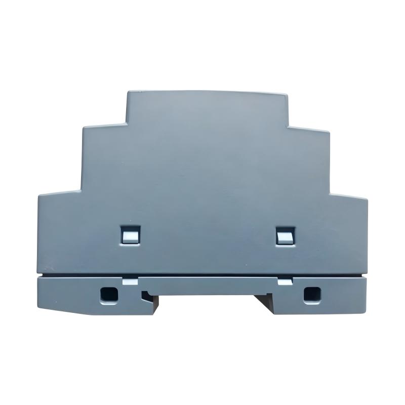
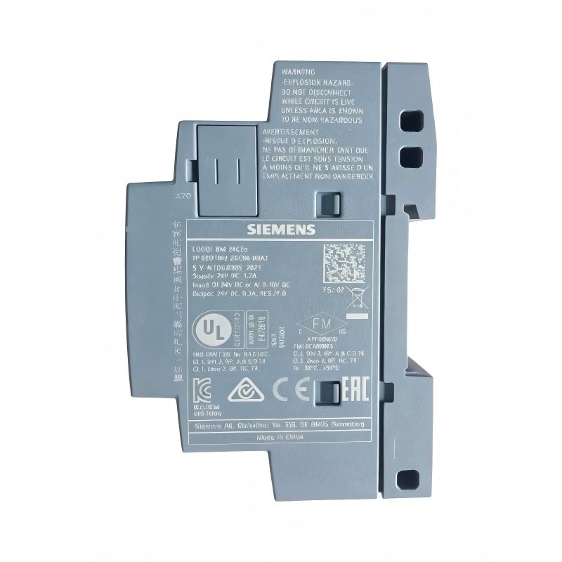
- Siemens
- 6AG1052-2CC08-7BA0
- SIPLUS LOGO! 24CEO Logic Module without Display
- Germany
- 71.5 × 90 × 58 mm
- 0.19kg
- Xiamen, China
- New & In Stock
- T/T, PayPal, Western Union
- 1 Year
- 1-3 Working Days
- DHL, UPS, TNT, FedEx and EMS.
- 24-Hour Service
- COO
- 5
Our advantage

Global Logistics
We have a 10-year logistics and express cooperation agreement, so our products can be shipped to any place in the world.

Brand new and original
Our products are imported in bulk from the place of origin. Because of the cooperative relationship, our products are all original and 100% new.

24-hour service
We provide 7*24 hours service to our customers. We will be there whenever you need us.

Price advantage
All our products are priced very favorably because we have our own warehouse and supply.
| Company Information | |||
| [email protected] | |||
| Mobile | +8615980777398 | ||
| +8615980777398 | |||
| 15980777398 |
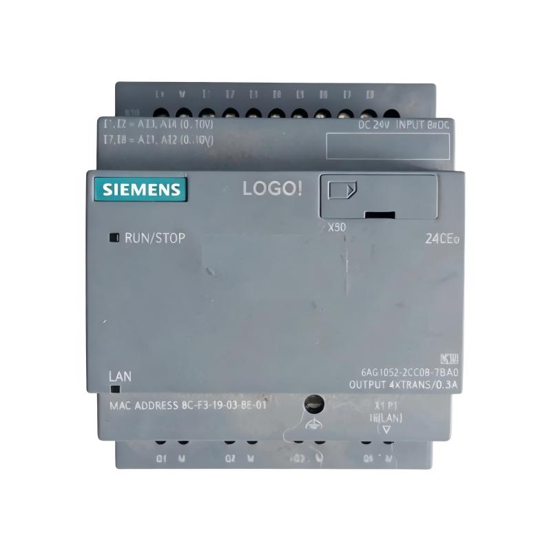
Siemens 6AG1052-2CC08-7BA0 — Detailed Product Profile
1. Product Overview
The Siemens 6AG1052-2CC08-7BA0 is a SIPLUS LOGO! 24CEO logic module designed for compact industrial automation, machine control and small-scale process applications. It combines programmable logic, built-in digital inputs and transistor outputs in a compact unit that can be mounted on a standard 35 mm DIN rail.
This model is based on the standard 6ED1052-2CC08-0BA0 LOGO! logic module. The SIPLUS version adds conformal coating and an extended environmental specification, with an operating-temperature range of -40°C to +70°C and a specified cold-start temperature of -25°C.
The module operates on a 24 V DC supply and provides eight digital inputs, four of which can also be used as 0–10 V analog inputs, together with four 24 V DC transistor outputs. It supports modular expansion, Ethernet communication, an integrated web server, data logging and user-defined web pages. A standard microSD card is used for compatible program and data functions.
The model is intended for applications that need straightforward programmable control without the complexity of a larger PLC system. It can be used for small machines, auxiliary equipment, lighting and ventilation control, simple monitoring systems and other tasks where its I/O capacity and electrical specifications are sufficient.
2. Brand and Product Series
| Item | Description |
|---|---|
| Brand | Siemens |
| Product family | SIPLUS |
| Automation product family | LOGO! |
| Product series | SIPLUS LOGO! basic modules without display |
| Product designation | SIPLUS LOGO! 24CEO |
| Model number | 6AG1052-2CC08-7BA0 |
| Standard base model | 6ED1052-2CC08-0BA0 |
| Product category | Programmable logic module |
| Display | No integrated display |
| Supply voltage | 24 V DC |
| Digital inputs | 8 |
| Inputs usable in analog mode | 4, 0–10 V |
| Digital outputs | 4 transistor outputs |
| Expansion capability | Modularly expandable |
| Ethernet | Integrated |
| Web server | Integrated |
| Data logging | Supported |
| User-defined web pages | Supported |
| Memory medium | Standard microSD card |
| Environmental protection | Conformal coating |
| Operating temperature | -40°C to +70°C |
| Cold-start temperature | -25°C |
| Mounting | 35 mm DIN rail |
The LOGO! family is intended for compact control tasks where a small programmable logic module can replace more complicated relay wiring or provide a simple controller for a dedicated machine function.
The SIPLUS designation identifies an environmentally enhanced variant. Its coating and temperature specification can be useful in industrial locations where the environmental conditions are more demanding than those of a conventional office or climate-controlled control cabinet. This does not mean the module is waterproof or suitable for every corrosive environment.
3. Detailed Technical Parameters
3.1 General specifications
| Parameter | Specification |
|---|---|
| Model | 6AG1052-2CC08-7BA0 |
| Product designation | SIPLUS LOGO! 24CEO |
| Standard base model | 6ED1052-2CC08-0BA0 |
| Product family | LOGO! 8 |
| Product type | Programmable logic module |
| Display | No integrated display |
| Mounting method | 35 mm DIN rail |
| DIN rail width | 4 spacing units |
| Rated supply voltage | 24 V DC |
| Permissible supply voltage | 20.4–28.8 V DC |
| Digital inputs | 8 |
| Inputs configurable for analog use | 4 |
| Analog input range | 0–10 V DC |
| Digital outputs | 4 |
| Output type | Transistor, 24 V DC |
| Maximum output current | 0.3 A per output under specified conditions |
| Output short-circuit protection | Electrical protection, specified at 1 A |
| Function block capacity | 400 blocks |
| Expansion capability | Yes |
| Ethernet interface | Integrated |
| Integrated web server | Yes |
| Data logging | Supported |
| User-defined web pages | Supported |
| Memory medium | Standard microSD card |
| Compatible programming software | LOGO! Soft Comfort V8 or later, subject to project compatibility |
| Degree of protection | IP20 |
| Conformal coating | Yes |
| Operating temperature | -40°C to +70°C |
| Specified cold-start temperature | -25°C |
| Physical dimensions (W × H × D) | 71.5 × 90 × 58 mm |
| Approximate physical/net weight | 0.192 kg |
| Mounting environment | Suitable control cabinet or protected installation |
| Product lifecycle note | Listed as a spare-part product; check availability and exact variant before ordering |
The module’s compact dimensions make it suitable for installations where control-cabinet space is limited. IP20 indicates protection against access to hazardous parts and solid foreign objects within the applicable classification; it does not provide protection against water ingress.
3.2 Digital inputs and analog input functions
| Parameter | Specification |
|---|---|
| Total integrated inputs | 8 |
| Digital input channels | 8 |
| Channels usable in analog mode | 4 |
| Analog signal range | 0–10 V DC |
| Typical digital input applications | Push buttons, limit switches, contact signals and compatible digital sensors |
| Typical analog input applications | Voltage-output sensors, simple level signals and compatible measurement devices |
| Input configuration | Defined in the LOGO! project |
| Signal compatibility | Must match the electrical input specifications |
| Field wiring | Depends on sensor type and installation design |
The eight inputs allow the module to monitor basic machine and process signals. Four of the inputs can also be used for analog measurements in the specified 0–10 V range. This provides flexibility for applications that combine discrete signals with a small number of analog values.
Examples include reading a compatible voltage-output sensor, checking a threshold, or using an analog value in a simple control sequence. The input range must be observed: a 4–20 mA sensor or a sensor with a different output range may require suitable signal-conditioning hardware.
3.3 Digital outputs
| Parameter | Specification |
|---|---|
| Number of outputs | 4 |
| Output technology | Transistor |
| Output supply | 24 V DC system |
| Maximum output current | 0.3 A per output under specified conditions |
| Short-circuit protection | Electrical protection, specified at 1 A |
| Suitable loads | Compatible low-current DC control loads |
| Typical applications | Indicator lights, interface relays and compatible control inputs |
| Direct motor switching | Not recommended unless a suitable external power interface is used |
| Inductive loads | Require appropriate suppression and circuit design |
| High-current loads | Require a suitable external relay, contactor or driver |
| Temperature-related derating | Observe the specified output-load limitations at elevated temperatures |
The transistor outputs are designed for DC switching and are useful for controlling compatible low-current devices. They are not equivalent to relay outputs, and they should not be used to switch AC loads directly.
For larger loads, motor circuits, solenoids or devices with significant inrush current, use a properly rated interface relay, contactor or driver. Confirm the output current, load characteristics and protective arrangement before connecting field equipment.
3.4 Program and logic functions
| Parameter | Specification |
|---|---|
| Maximum function blocks | 400 |
| Programming environment | LOGO! Soft Comfort |
| Basic logic operations | Supported |
| Timers | Supported |
| Counters | Supported |
| Time-based switching | Supported |
| Analog threshold processing | Supported for compatible analog inputs |
| Mathematical and comparison functions | Supported according to the LOGO! instruction set |
| Data retention | Supported for applicable functions and configuration |
| Password protection | Supported by compatible software and configuration |
| Program transfer | Via compatible memory card and supported engineering methods |
| Function-block linking | Supported within the program capacity |
| Program compatibility | Depends on software version and hardware generation |
The 400-block capacity is useful for small and medium control tasks that require multiple interlocking conditions, timers, counters and operating modes. The actual complexity of a program depends on the number and type of blocks used, the data-processing requirements and the design of the control sequence.
For maintenance work, keep a backup of the original project and record the programming software version. Projects created for a later LOGO! generation may require adjustments before they can be used with an older module.
3.5 Ethernet, web server and data logging
| Parameter | Specification |
|---|---|
| Ethernet interface | Integrated |
| Web server | Integrated |
| User-defined web pages | Supported |
| Data logging | Supported |
| Remote status monitoring | Possible through compatible configured interfaces |
| Network configuration | Required |
| Access control | Must be configured according to the installation’s security requirements |
| microSD support | Standard microSD card for compatible functions |
| Cloud connectivity | Do not assume support for every modern cloud service; verify the exact hardware and software generation |
| Internet exposure | Requires appropriate network-security measures |
Ethernet connectivity allows the logic module to exchange data with compatible devices and support selected monitoring and engineering functions. The integrated web server can provide access to configured status information and user-defined pages.
Data logging can be useful for recording operating values or event-related information for later review. The quantity and retention of records depend on the configured application, storage capacity and supported firmware functions.
Because this is an older product variant, its networking features should be assessed according to its actual software generation. Modern protocols and services should not be assumed to be available simply because the module has Ethernet.
3.6 Time functions and internal resources
| Parameter | Specification |
|---|---|
| Time-switching functions | Supported |
| Maximum number of time-switching clocks | Up to 400, function-dependent |
| Time-switching clock power reserve | Approximately 480 hours |
| Function-block capacity | 400 |
| Timers and counters | Supported |
| Scheduling applications | Supported within the available time functions |
| Time-dependent control | Supported |
| Clock-dependent operation | Verify time retention and configuration for the actual installation |
Time functions can be used for lighting schedules, ventilation periods, pump operation windows and other simple automated sequences. The available clock functions are determined by the specific module generation and program configuration.
For installations where schedules are important, confirm the time settings and the behaviour of the controller after a prolonged power interruption.
3.7 Electrical and environmental specifications
| Parameter | Specification |
|---|---|
| Rated supply voltage | 24 V DC |
| Lower permissible supply voltage | 20.4 V DC |
| Upper permissible supply voltage | 28.8 V DC |
| Operating temperature | -40°C to +70°C |
| Cold-start temperature | -25°C |
| Storage/transport temperature | -40°C to +70°C |
| Degree of protection | IP20 |
| Environmental design | SIPLUS conformal coating |
| High-temperature output limitation | Above +55°C, maximum output load is restricted to 0.2 A per output under the specified conditions |
| Installation altitude | Up to 5,000 m, subject to the specified ambient-temperature and pressure derating rules |
| Humidity and condensation | Follow the applicable installation conditions |
| Water protection | No direct water protection implied by IP20 |
| Enclosure requirement | Use a suitable cabinet or protected location |
| Electromagnetic compatibility | Installation and wiring must follow applicable requirements |
One important detail is the output-load restriction at higher temperatures. Although the module’s stated operating range extends to +70°C, the maximum permissible output current is reduced above +55°C under the specified conditions. The temperature rating therefore should not be interpreted as permission to operate every output at its maximum load throughout the entire temperature range.
3.8 Physical dimensions and weight
| Physical parameter | Specification |
|---|---|
| Width | 71.5 mm |
| Height | 90 mm |
| Depth | 58 mm |
| Overall dimensions (W × H × D) | 71.5 × 90 × 58 mm |
| Approximate net weight | 0.192 kg |
| DIN rail mounting | 35 mm |
| Mounting width | 4 spacing units |
| Display clearance | No integrated display |
| Wiring clearance | Allow additional space for terminals and conductors |
| Cabinet planning | Account for adjacent modules, ventilation and service access |
The physical module occupies a relatively small footprint, making it useful for compact control panels. When planning an enclosure, allow room for wiring bends, terminal access, cable routing and heat dissipation. The dimensions above refer to the module itself rather than the shipping package.
4. Product Introduction
The 6AG1052-2CC08-7BA0 is a compact programmable logic module for applications that need reliable, straightforward control without the cost or complexity of a larger automation system. It brings together basic logic processing, digital inputs, analog-capable input channels, transistor outputs and Ethernet communication in a small DIN-rail-mounted unit.
The module can replace groups of conventional control relays in suitable applications. Instead of physically wiring every operating condition through a network of relays and timers, the required logic can be created in LOGO! Soft Comfort and downloaded to the controller. This makes it easier to adjust control sequences, add timing conditions and change operating modes during maintenance.
Its eight integrated inputs allow the module to monitor signals such as push buttons, limit switches and compatible sensors. Four inputs can also be configured for 0–10 V analog signals, allowing simple measurement and threshold-control functions. The four transistor outputs are suited to compatible 24 V DC control loads, including interface relays and indicator devices.
The integrated Ethernet interface, web server and data-logging functions provide additional flexibility. Depending on the configuration, an operator or maintenance technician can review operating information, access configured web pages or examine recorded data without adding a separate display to the module itself.
The SIPLUS version is especially relevant where the equipment must operate under more demanding environmental conditions. Its conformal coating and specified -40°C to +70°C operating range distinguish it from a conventional indoor-use logic module. The specified cold-start temperature is -25°C, and the output-load restrictions at elevated temperatures must be taken into account.
5. Product Applications
5.1 Small machine automation
The module is well suited to machines with a limited number of sensors and actuators. Typical examples include small assembly fixtures, simple packaging equipment, automatic feeders and auxiliary machinery.
A basic program can monitor operating buttons and position switches, apply timing conditions and activate suitable control outputs. The logic can be modified through the engineering software without rebuilding the entire control circuit.
5.2 Pump and water-level control
For a suitable low-voltage control arrangement, the module can monitor level switches or compatible analog level sensors and control a pump through an appropriately rated contactor or interface relay.
Typical functions include:
– Starting a pump when a tank level falls below a defined threshold.
– Stopping the pump when the required level is reached.
– Applying a delay before restarting the pump.
– Generating an indication when a sensor reports an abnormal condition.
– Alternating between operating modes where the program and I/O capacity permit.
The module should not switch a pump motor directly through its small transistor outputs. A suitable motor starter or contactor and correctly rated protection are required.
5.3 Lighting and building automation
The controller can manage simple lighting schedules, ventilation timing and other basic building-control tasks. Its time-switching functions allow equipment to operate according to programmed schedules or selected conditions.
For example, a control program could switch lighting on during defined hours, activate ventilation when an input reaches a threshold or disable a circuit when a monitored condition is not met. The exact design depends on the available signals and the requirements of the installation.
5.4 Ventilation and temperature-related control
Where compatible sensors and signal-conditioning equipment are available, the analog-capable inputs can be used to monitor voltage signals representing temperature, pressure or other process values.
The logic module can compare the measured value with configured thresholds and operate suitable control outputs. For applications requiring precision measurement, closed-loop regulation, extensive analog I/O or advanced process-control functions, a more capable controller may be a better choice.
5.5 Conveyor and material-handling equipment
Small conveyors and transfer stations often require straightforward sequencing. The controller can monitor start/stop commands, position switches and other discrete signals, then operate compatible control devices in the required order.
Timers can be used to introduce delays, while counters can track selected events. Where multiple conveyor sections must coordinate, the communication architecture and total I/O requirements should be reviewed before selecting the module.
5.6 Industrial monitoring and status indication
The integrated Ethernet interface, web server and data logging can support simple monitoring tasks. For example, a program may record operating events, maintain a count of machine cycles or provide selected status information through a configured web interface.
This can be useful for maintenance and troubleshooting. It is not a substitute for a dedicated industrial monitoring platform when the application requires extensive data collection, long-term storage, advanced alarm management or stringent cybersecurity controls.
5.7 Environmental control in demanding locations
The SIPLUS version may be suitable for selected installations where low or high ambient temperatures make an ordinary control module less appropriate. Examples can include protected industrial cabinets in unheated spaces or equipment subject to seasonal temperature changes.
The actual environment must remain within the module’s specified limits. Direct water exposure, uncontrolled condensation and unqualified chemical exposure require separate evaluation and appropriate enclosure protection.
5.8 Simple equipment retrofits
The module can be useful when modernizing an existing relay-based control panel. A suitable LOGO! program can combine several timing and logic functions in one compact device, reducing the number of separate control components.
Before a retrofit, confirm the voltage of every field signal, the output type required by each load, the total I/O count and the available cabinet space. Existing relay wiring should not be transferred directly to transistor outputs without checking electrical compatibility.
6. Main Product Advantages
6.1 Compact design
The module measures approximately 71.5 × 90 × 58 mm and mounts on a 35 mm DIN rail. This helps conserve cabinet space and allows it to fit into many compact control-panel layouts.
Its four-spacing-unit mounting width also makes it relatively easy to arrange alongside compatible protection devices, terminals and expansion modules.
6.2 Integrated digital and analog-capable inputs
Eight integrated inputs provide a useful starting point for small control systems. Four can be used in analog mode for 0–10 V signals, allowing the controller to handle both discrete states and simple voltage measurements.
This combination can reduce the need for additional input hardware in applications with modest analog requirements.
6.3 Four transistor outputs
The four transistor outputs support fast, straightforward switching of compatible DC control loads. They are useful for signalling, interface relays and other low-current devices.
Because the outputs are transistor-based rather than relay contacts, the load type and current must be checked carefully. AC loads and high-current devices require an appropriate external switching component.
6.4 Flexible programmable logic
The module supports up to 400 function blocks. This gives users a practical range of logic, timer, counter and comparison functions for compact machines and simple automation tasks.
Programming changes are generally easier to maintain than a complicated relay circuit, especially when the original project file and documentation are available.
6.5 Integrated Ethernet connectivity
The built-in Ethernet interface allows the module to communicate with compatible devices and supports selected engineering and monitoring functions.
This can simplify integration into a small industrial network, although the required communication settings, supported services and network-security arrangements must be configured correctly.
6.6 Web server and user-defined pages
The integrated web server and user-defined web pages can provide a simple way to present selected operating information. Depending on the project, this can help maintenance personnel review equipment status without a dedicated display mounted directly on the controller.
Access should be restricted appropriately, especially where the network is connected to a wider plant network or external systems.
6.7 Data logging
Data logging can help record selected operating values and events. Such records may assist troubleshooting, cycle counting and basic performance review.
The practical amount of data retained depends on the configured logging function and the storage medium. For applications needing extensive historical records, a dedicated data-collection system may be more appropriate.
6.8 Expanded environmental specification
The conformal coating and specified operating-temperature range of -40°C to +70°C are useful features for demanding industrial environments. They can provide additional installation flexibility when the surrounding conditions are within the module’s approved limits.
The reduced output-current limit above +55°C must still be respected.
6.9 Modular expansion
The LOGO! platform supports compatible expansion modules, allowing a control system to grow beyond the integrated I/O when necessary. Expansion choices depend on the precise module generation, electrical interface and system configuration.
This can be helpful when a small machine acquires additional sensors or requires more output channels over time.
6.10 Straightforward maintenance
The combination of a programmable logic environment, compact mounting and built-in I/O can make the module relatively easy to maintain in simple automation installations.
Good maintenance practice includes keeping the program backup, recording the software version, labelling field wiring and documenting the output loads and protection devices.
7. Five Related Models
The following models are closely related to the LOGO! logic-module family or are useful companion products. Their input/output arrangements and electrical characteristics differ, so they should be selected according to the actual application rather than treated as interchangeable units.
| Model | Product designation | Main parameters | Dimensions (W × H × D) | Weight (kg) |
|---|---|---|---|---|
| 6ED1052-2CC08-0BA0 | LOGO! 24CEO standard base model | 24 V DC; 8 digital inputs, 4 usable as 0–10 V analog inputs; 4 transistor outputs; Ethernet; 400 function blocks | 71.5 × 90 × 58 mm | Approx. 0.192 |
| 6AG1052-2MD08-7BA0 | SIPLUS LOGO! 12/24RCEO | 12/24 V DC variant; 8 inputs, 4 usable in analog mode; 4 relay outputs; Ethernet; extended environmental specification | 71.5 × 90 × 60 mm | Approx. 0.235 |
| 6AG1052-2HB08-7BA0 | SIPLUS LOGO! 24RCEO (AC) | 24 V DC/AC-compatible supply variant; 8 inputs; 8 relay outputs; Ethernet; conformal coating | 71.5 × 90 × 60 mm | Approx. 0.235 |
| 6AG1052-2FB08-7BA0 | SIPLUS LOGO! 230RCEO | 115/230 V AC/DC supply variant; 8 digital inputs; 4 relay outputs; Ethernet; conformal coating | 71.5 × 90 × 60 mm | Approx. 0.254 |
| 6ED1055-1CB00-0BA2 | LOGO! DM8 24 digital expansion module | Expansion module; 24 V DC; 4 digital inputs and 4 digital outputs; intended for compatible LOGO! systems | Verify exact installed configuration | Verify exact variant |
Dimensions and weights for related models are indicative figures and may vary by hardware generation or variant. Verify the complete order number and mechanical data before designing a panel or purchasing a replacement.
7.1 6ED1052-2CC08-0BA0 — Standard LOGO! 24CEO
This is the standard base-model counterpart of the SIPLUS module. It provides the same general type of compact logic control, including 24 V DC operation, eight inputs, four transistor outputs and Ethernet connectivity.
The main distinction is the environmental specification. The SIPLUS variant is intended for the specified extended environmental conditions, whereas the standard variant should be selected according to its own rated limits.
7.2 6AG1052-2MD08-7BA0 — SIPLUS LOGO! 12/24RCEO
This model is relevant when relay outputs are required instead of transistor outputs. Relay contacts can be more flexible for certain load types, subject to the rated voltage, current and switching characteristics.
Its supply-voltage arrangement also differs from the 24 V DC-only configuration of the target model. Confirm the exact input and supply requirements before connecting field wiring.
7.3 6AG1052-2HB08-7BA0 — SIPLUS LOGO! 24RCEO (AC)
This variant offers relay outputs and a different supply arrangement. It may be suitable where the application needs relay contacts or where the control panel has a compatible supply system.
The relay outputs are not automatically suitable for every motor or high-current load. External contactors and circuit protection may still be necessary.
7.4 6AG1052-2FB08-7BA0 — SIPLUS LOGO! 230RCEO
This variant is intended for applications requiring a different supply-voltage arrangement and relay outputs. It can be considered for control panels designed around compatible higher-voltage supplies.
Because the supply and input characteristics differ significantly from the target model, it should not be selected as a direct replacement without checking the entire electrical design.
7.5 6ED1055-1CB00-0BA2 — LOGO! DM8 24 expansion module
This is a companion expansion module rather than a standalone controller. It can add digital input and output capacity to a compatible LOGO! system.
Before selecting an expansion module, confirm compatibility with the base unit’s generation, expansion limits and program configuration. The expansion module does not replace the main logic module.
8. Five Popular Models from the Same Brand
The following table presents five widely used product types from the Siemens automation portfolio. They cover compact control, modular PLCs, distributed I/O, industrial power and operator interfaces. They are not all members of the LOGO! family and should not be treated as direct replacements for the target logic module.
| Model | Series / product type | Main parameters | Dimensions (W × H × D) | Weight (kg) |
|---|---|---|---|---|
| 6ES7214-1AG40-0XB0 | SIMATIC S7-1200 CPU 1214C | Compact PLC; integrated digital I/O and Ethernet; suitable for small and medium machine control | Approx. 110 × 100 × 75 mm | Approx. 0.415 |
| 6ES7511-1AK02-0AB0 | SIMATIC S7-1500 CPU 1511-1 PN | Modular PLC; PROFINET interface; for more demanding machine and process automation | Approx. 35 × 147 × 129 mm | Approx. 0.650 |
| 6ES7155-6AU01-0BN0 | SIMATIC ET 200SP interface module | Distributed I/O interface for compatible ET 200SP stations; modular field I/O architecture | Approx. 50 × 117 × 74 mm; verify exact configuration | Approx. 0.200; verify exact variant |
| 6EP1333-2BA20 | SITOP industrial power supply | 24 V DC power supply; capacity and output current depend on the exact variant | Approx. 90 × 90 × 100 mm; verify exact variant | Approx. 0.700; verify exact variant |
| 6AV2123-2GB03-0AX0 | SIMATIC HMI Basic Panel | Operator interface for machine status, alarms and control screens | Approx. 214 × 158 × 39 mm; verify exact variant | Approx. 0.500; verify exact variant |
The dimensions and weights in this table are approximate selection figures, not guaranteed mechanical specifications. Confirm the exact order number, revision and accessory configuration before purchasing or designing an enclosure.
8.1 6ES7214-1AG40-0XB0 — SIMATIC S7-1200
The S7-1200 is a compact PLC platform for small and medium-sized machines. Compared with a LOGO! logic module, it is intended for applications that need a more capable PLC architecture, greater flexibility in program structure or a different range of I/O and communication options.
It may be appropriate when a project has outgrown the LOGO! platform. The transition involves reviewing the control program, I/O mapping, network settings and engineering environment rather than simply replacing one module with another.
8.2 6ES7511-1AK02-0AB0 — SIMATIC S7-1500
The S7-1500 family is designed for more demanding automation applications. It is a candidate for systems that require a modular PLC architecture, more extensive engineering functions or broader integration into a production system.
It is generally more complex than a small LOGO! installation. The additional capabilities may be useful in a larger project but unnecessary for a simple timer, pump or lighting controller.
8.3 6ES7155-6AU01-0BN0 — SIMATIC ET 200SP
This interface module belongs to a distributed I/O platform. It is useful when a control system needs to place field I/O close to the machinery and connect it to a compatible controller.
ET 200SP is a different product family from LOGO!. Its modules, mounting arrangement and engineering requirements should be evaluated as part of a complete system design.
8.4 6EP1333-2BA20 — SITOP power supply
A suitable industrial power supply is essential for stable operation of a control system. The correct model must match the supply voltage, current demand, load characteristics and protective requirements of the installation.
When selecting a power supply for the 6AG1052-2CC08-7BA0, account for the logic module, expansion modules, sensors, interface relays and other connected devices. Do not select the supply based only on the controller’s nominal voltage.
8.5 6AV2123-2GB03-0AX0 — SIMATIC HMI Basic Panel
An HMI panel provides an operator-facing interface for machine status, alarms and selected commands. It can be helpful when the application needs a more convenient way to display operating information than a controller without an integrated display.
For integration with a LOGO! system, check the panel’s communication compatibility, engineering software requirements and supported protocols. An HMI is an optional companion device, not a replacement for the logic module itself.
9. Installation and Selection Considerations
Before installing or replacing the 6AG1052-2CC08-7BA0, review these practical points.
1. Confirm the complete model number. The SIPLUS and standard versions have different environmental specifications. Similar model numbers do not guarantee identical capabilities.
2. Check the input signals. The module has eight inputs, with four usable for 0–10 V analog signals. Verify sensor output types, reference connections and voltage limits before wiring.
3. Check output compatibility. The four outputs are transistor outputs, not relay contacts. Confirm the DC load type, maximum current and any required external interface.
4. Observe high-temperature output derating. Above +55°C, the permitted output load is restricted to 0.2 A per output under the specified conditions.
5. Provide a suitable 24 V DC supply. The permitted range is 20.4–28.8 V DC. Ensure that the supply has enough capacity for the module and all connected devices.
6. Use appropriate protection. Select fuses or circuit breakers, wiring sizes and interface components according to the actual load and applicable electrical regulations.
7. Confirm expansion compatibility. Check that any additional I/O module belongs to a compatible generation and is supported by the base unit.
8. Allow room for wiring. The physical dimensions are approximately 71.5 × 90 × 58 mm. Additional cabinet space is needed for conductors, terminals and cable routing.
9. Plan for environmental conditions. The operating range is -40°C to +70°C, with a specified cold-start temperature of -25°C. Keep the equipment within its permitted conditions and use a suitable enclosure.
10. Back up the project. Keep the original LOGO! Soft Comfort program, record the software version and document important parameters before making changes.
11. Secure network access. If Ethernet or web-server functions are used, restrict access appropriately and avoid exposing the controller directly to untrusted networks.
12. Check product availability. This particular model is listed as a spare-part product. Confirm the exact variant and available replacement options before planning a new installation around it.
10. Final Assessment
The Siemens 6AG1052-2CC08-7BA0 is a compact SIPLUS LOGO! 24CEO programmable logic module intended for straightforward industrial control. Its main specifications include 24 V DC operation, eight digital inputs, four inputs configurable for 0–10 V analog signals, four transistor outputs, 400 function blocks, integrated Ethernet, a web server and data logging.
Its compact 71.5 × 90 × 58 mm form factor and approximate 0.192 kg weight make it suitable for space-conscious control panels. The conformal coating and specified -40°C to +70°C operating range provide additional environmental capability, subject to the cold-start condition and output-load restrictions at elevated temperatures.
The module is a practical choice for small machines, pump control, lighting schedules, ventilation, basic monitoring and other applications that fit its I/O capacity and programming model. For systems that need relay outputs, more extensive I/O, higher processing capacity or more advanced communication functions, a related LOGO! variant or a larger PLC platform may be more appropriate.
When choosing a replacement or planning a new system, prioritize electrical compatibility, output type, environmental requirements, expansion capability and software-generation compatibility. These details matter more than the similarity of the product names alone.