

ProductPRODUCT
Featured products








Contact Us
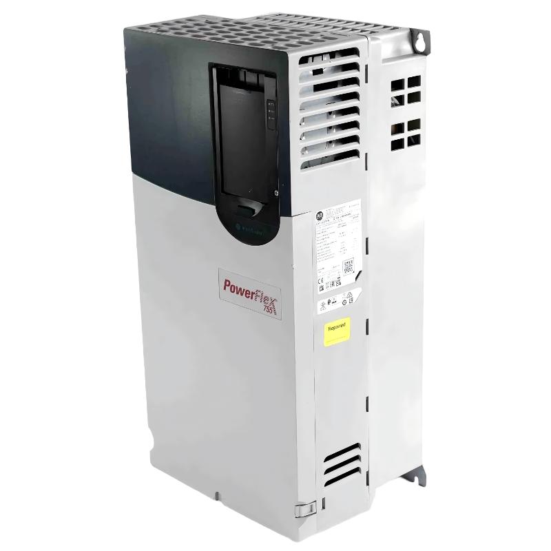
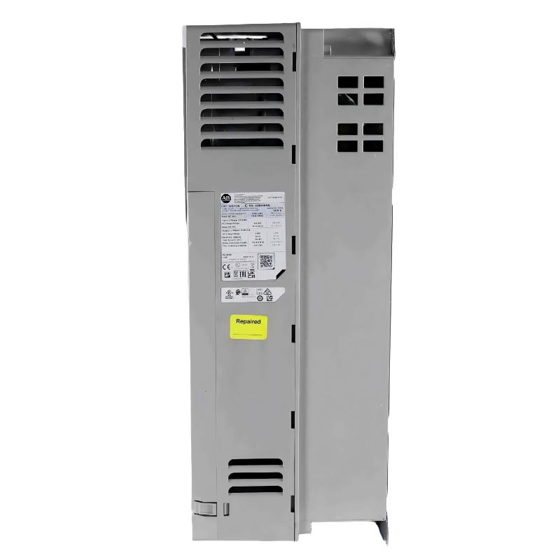
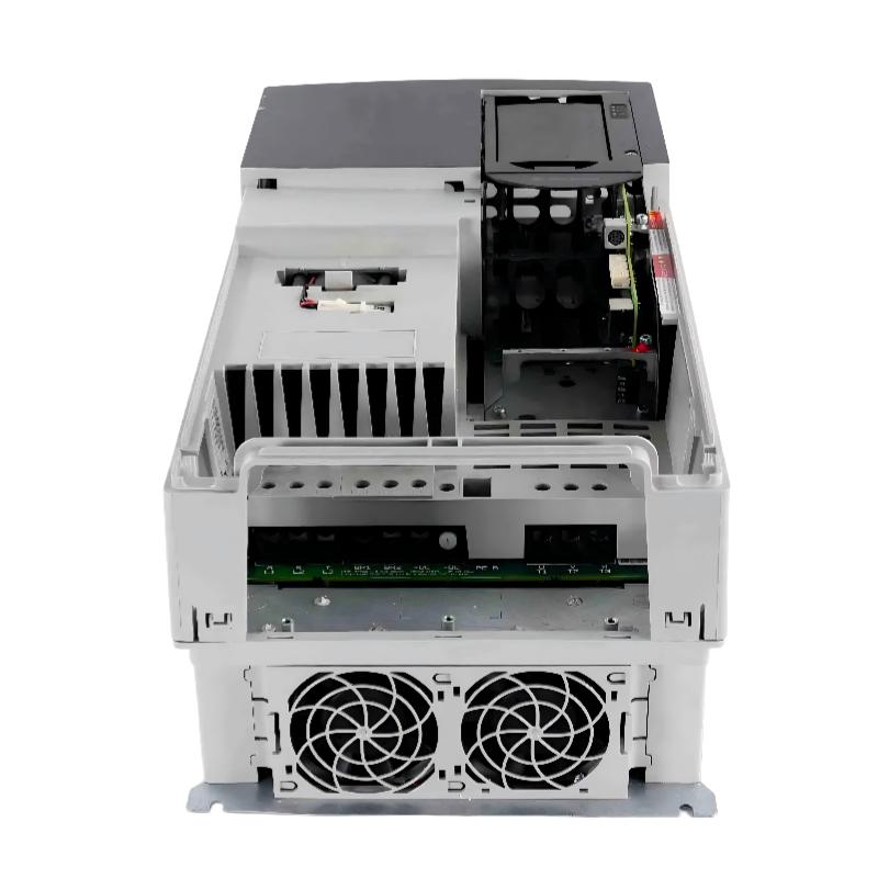
- Allen Bradley
- 20G14NF212JA0NNNNN
- PowerFlex AC Drive
- USA
- 430 × 881.5 × 349.6 mm
- 108.9kg
- Xiamen, China
- New & In Stock
- T/T, PayPal, Western Union
- 1 Year
- 1-3 Working Days
- DHL, UPS, TNT, FedEx and EMS.
- 24-Hour Service
- COO
- 39
Our advantage

Global Logistics
We have a 10-year logistics and express cooperation agreement, so our products can be shipped to any place in the world.

Brand new and original
Our products are imported in bulk from the place of origin. Because of the cooperative relationship, our products are all original and 100% new.

24-hour service
We provide 7*24 hours service to our customers. We will be there whenever you need us.

Price advantage
All our products are priced very favorably because we have our own warehouse and supply.
| Company Information | |||
| [email protected] | |||
| Mobile | +8615980777398 | ||
| +8615980777398 | |||
| 15980777398 |
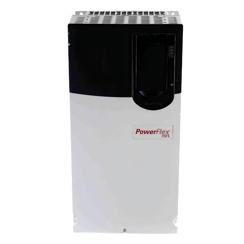
Allen-Bradley 20G14NF212JA0NNNNN PowerFlex 755 AC Drive — Detailed Product Guide, Specifications, Applications, Advantages, and Recommended Models
1. Product Overview
The Allen-Bradley 20G14NF212JA0NNNNN is a high-power PowerFlex 755 air-cooled AC drive designed for demanding industrial motor-control applications. It is a 690 VAC, three-phase drive with a rated Normal Duty output of 212 A / 200 kW and a Heavy Duty rating of 160 kW at 171 A.
This model is part of the PowerFlex 755 family and is intended for applications where reliable variable-speed motor control, high power capacity, network integration, and flexible system architecture are important.
The drive uses a DC input with precharge configuration and is supplied as an open-type, IP20/IP00-class drive with forced-air cooling. It also incorporates an embedded Ethernet/IP interface, making it suitable for integration into modern industrial automation systems.
One of the most important characteristics of this particular catalog number is the JA0 configuration. The JA0 configuration includes an internal dynamic braking transistor, providing the drive with a practical interface for dynamic braking applications when an appropriately selected external braking resistor is required.
The unit is supplied with no HIM installed, meaning the front-mounted Human Interface Module is blank/not included. This arrangement is often useful in cabinet-based installations where configuration, monitoring, and control are handled through a PLC, industrial network, remote HMI, or engineering workstation.
2. Basic Product Identification
| Parameter | Specification |
|---|---|
| Brand | Allen-Bradley |
| Product Family | PowerFlex 755 |
| Product Type | Air-Cooled AC Drive |
| Catalog / Part Number | 20G14NF212JA0NNNNN |
| Drive Series | PowerFlex 755 |
| Input Voltage Class | 690 VAC |
| Input Phase | 3 Phase |
| Input Configuration | DC Input with Precharge |
| Normal Duty Current | 212 A |
| Normal Duty Power | 200 kW |
| Heavy Duty Current | 171 A |
| Heavy Duty Power | 160 kW |
| Cooling Method | Forced Air / Air Cooled |
| Enclosure Style | Open Type |
| Protection Class | IP20/IP00 |
| Frame Size | Frame 7 |
| Dynamic Braking | Internal DB Transistor |
| Braking Resistor | External resistor required when braking resistor function is used |
| EMC / Filtering | Filtered |
| CM Jumper | Installed |
| Human Interface Module | Blank / No HIM |
| Network Capability | Embedded Ethernet/IP |
| Mounting Concept | Cabinet / Panel Installation |
| Approx. Dimensions | 430 × 881.5 × 349.6 mm |
| Approx. Weight | 72.6–108.9 kg |
| Typical Application Level | High-Power Industrial Motor Control |
3. Detailed Electrical Specifications
The electrical rating of the 20G14NF212JA0NNNNN places it toward the upper end of the standard 690 VAC PowerFlex 755 air-cooled range.
Its 212 A Normal Duty rating corresponds to 200 kW, while its Heavy Duty rating is 171 A / 160 kW. This dual-rating concept is important because the correct drive selection depends not only on motor nameplate power but also on the mechanical load profile.
For applications involving pumps, fans, compressors, and other relatively smooth loads, the Normal Duty rating may be the appropriate reference.
For applications involving higher overload demand, frequent acceleration, heavy starting loads, conveyors, mixers, crushers, hoists, or other mechanically demanding equipment, the Heavy Duty rating is normally the more important selection point.
| Electrical Parameter | Specification |
|---|---|
| Model / Part Number | 20G14NF212JA0NNNNN |
| Rated Voltage | 690 VAC |
| Phase | 3 Phase |
| Normal Duty Current | 212 A |
| Normal Duty Power | 200 kW |
| Heavy Duty Current | 171 A |
| Heavy Duty Power | 160 kW |
| Input Arrangement | DC Input with Precharge |
| Output Type | Variable-Frequency AC Motor Output |
| Cooling | Forced Air |
| Frame | 7 |
| Dynamic Braking | DB Transistor Included |
| Filtering | Filtered |
| CM Jumper | Installed |
| Network | Embedded Ethernet/IP |
| HIM | No HIM / Blank |
| Enclosure | Open Type |
| Dimensions | 430 × 881.5 × 349.6 mm |
| Weight | Approximately 72.6–108.9 kg |
4. Normal Duty and Heavy Duty Ratings
The difference between Normal Duty and Heavy Duty is one of the most useful specifications when evaluating this drive.
The Normal Duty rating is 200 kW at 212 A. This rating is well suited to applications where the motor normally operates with relatively stable loading and where the required overload capability is less severe.
The Heavy Duty rating is 160 kW at 171 A. This provides a lower continuous power rating but is intended for applications with greater overload requirements.
A common mistake in drive selection is to select a drive based solely on the motor’s nominal kW value. For industrial machinery, the acceleration torque, peak torque, duty cycle, speed range, starting characteristics, and overload requirements can be just as important as the motor’s nameplate power.
| Rating Type | Current | Power | Typical Application Character |
|---|---|---|---|
| Normal Duty | 212 A | 200 kW | Pumps, fans, compressors, process machinery with relatively stable load |
| Heavy Duty | 171 A | 160 kW | Conveyors, mixers, material handling, high-inertia machinery, demanding acceleration |
| Drive Frame | — | Frame 7 | High-power cabinet-mounted installation |
| Cooling | — | Forced Air | Requires suitable cabinet ventilation / thermal management |
5. Mechanical Specifications
The 20G14NF212JA0NNNNN is a Frame 7 drive. Compared with the smaller Frame 6 versions of the PowerFlex 755 family, Frame 7 equipment requires substantially more cabinet space and more attention to installation logistics.
The approximate mechanical envelope is 430 mm wide × 881.5 mm high × 349.6 mm deep.
The weight is approximately 72.6–108.9 kg, depending on configuration and installed hardware. For cabinet design, lifting arrangements, mounting hardware, shipping equipment, and enclosure structural calculations, the actual delivered configuration should be checked before finalizing the mechanical design.
| Mechanical Parameter | Specification |
|---|---|
| Model / Part Number | 20G14NF212JA0NNNNN |
| Frame | Frame 7 |
| Cooling | Forced Air |
| Width | Approx. 430 mm |
| Height | Approx. 881.5 mm |
| Depth | Approx. 349.6 mm |
| Dimensions | Approx. 430 × 881.5 × 349.6 mm |
| Weight | Approx. 72.6–108.9 kg |
| Enclosure Type | Open Type |
| Installation | Panel / Cabinet |
| Mounting Orientation | Vertical cabinet installation |
| Thermal Management | Forced-air ventilation required |
| Service Space | Adequate front and ventilation clearance required |
6. Product Introduction
The PowerFlex 755 platform was developed for industrial applications that require more than basic speed control.
The platform provides a flexible architecture for large motors and sophisticated machinery. Instead of treating the drive simply as a device that converts fixed-frequency electrical power into variable-frequency output, the PowerFlex 755 family is designed as part of a larger automation system.
For a machine builder, this means that the drive can be integrated into the machine’s control architecture rather than operated as an isolated motor controller.
The 20G14NF212JA0NNNNN is particularly suited to large motors where 690 VAC distribution is preferred. The higher voltage class allows large motor power to be handled at lower current than would be required at lower voltage classes, which can be advantageous when designing high-power motor systems.
The embedded Ethernet/IP capability also makes the drive suitable for applications in which the PLC or supervisory control system needs access to drive operating information, commands, status information, alarms, and diagnostic data.
7. Product Series
The product belongs to the PowerFlex 755 series.
The PowerFlex 755 is part of the PowerFlex 750-Series architecture and is aimed at medium- to high-performance industrial drive applications.
The series covers a broad range of power levels, voltage classes, frame sizes, braking configurations, filtering configurations, and control options.
For large industrial machinery, the main advantage of selecting a drive from the same series is consistency. Engineering teams can use similar control concepts, network structures, commissioning procedures, and maintenance practices across multiple drive sizes.
| Series Parameter | Specification |
|---|---|
| Brand | Allen-Bradley |
| Series | PowerFlex 755 |
| Product Family | PowerFlex 750-Series |
| Model / Part Number | 20G14NF212JA0NNNNN |
| Product Type | High-Power AC Drive |
| Cooling Family | Air Cooled |
| Voltage Class | 690 VAC |
| Frame | Frame 7 |
| Intended System | Industrial Automation / Motor Control |
8. Dynamic Braking Configuration
The JA0 portion of the catalog number is especially important.
This configuration includes an internal dynamic braking transistor.
Dynamic braking is useful when the motor or driven machine has substantial stored kinetic energy and needs to decelerate faster than normal regenerative behavior would allow.
During deceleration, the motor can return energy toward the DC bus. The dynamic braking circuit provides a controlled method for handling this energy through a properly selected external braking resistor.
The internal transistor does not mean that a braking resistor is physically built into the drive. The resistor is normally an external component selected according to the required braking power, duty cycle, resistance, and thermal requirements.
| Braking Parameter | Specification |
|---|---|
| Model / Part Number | 20G14NF212JA0NNNNN |
| Dynamic Braking Transistor | Included |
| Internal Braking Resistor | Not included |
| External Braking Resistor | Required when braking function is used |
| Main Purpose | Dissipate excess DC-bus energy during braking |
| Typical Applications | High-inertia loads, rapid deceleration, conveyors, centrifuges, machine tools |
| Selection Requirement | Resistor must be correctly sized for braking energy and duty cycle |
9. JA0 Versus JN0 Configuration
A particularly useful comparison is between the JA0 and JN0 versions of the same 212 A drive.
The electrical power rating is essentially the same, but the braking configuration is different.
The JA0 version includes the dynamic braking transistor, while the JN0 version does not include the internal dynamic braking transistor.
This makes JA0 more suitable where braking hardware is part of the original machine design or where future braking requirements are anticipated.
| Parameter | JA0 Version | JN0 Version |
|---|---|---|
| Model / Part Number | 20G14NF212JA0NNNNN | 20G14NF212JN0NNNNN |
| Voltage | 690 VAC | 690 VAC |
| Normal Duty | 212 A / 200 kW | 212 A / 200 kW |
| Heavy Duty | 171 A / 160 kW | 171 A / 160 kW |
| Frame | Frame 7 | Frame 7 |
| Dynamic Braking Transistor | Included | Not Included |
| Internal Braking Resistor | No | No |
| Cooling | Forced Air | Forced Air |
| Filtering | Filtered | Filtered |
| CM Jumper | Installed | Installed |
| HIM | Blank / No HIM | Blank / No HIM |
| Dimensions | Approx. 430 × 881.5 × 349.6 mm | Approx. 430 × 881.5 × 349.6 mm |
| Weight | Approx. 72.6–108.9 kg | Approx. 72.6–108.9 kg |
10. Main Applications
10.1 Pumps
The drive is well suited to large industrial pumping systems.
Variable-speed control allows the pump motor speed to be adjusted according to process requirements instead of operating continuously at full speed.
This can be useful in water treatment, process plants, industrial cooling systems, large circulation systems, and other fluid-handling applications.
The 200 kW Normal Duty rating makes the model suitable for relatively large pumping equipment, provided that the motor current and operating conditions remain within the drive’s rating.
10.2 Fans and Blowers
Large industrial fans and blowers can benefit significantly from variable-speed control.
Instead of using mechanical dampers to restrict airflow while the motor continues operating at high speed, the drive can adjust motor speed to match the required airflow.
For applications with relatively smooth torque characteristics, the Normal Duty rating can be particularly useful.
10.3 Conveyors
The drive can be used for large conveyor systems where controlled acceleration and deceleration are important.
Dynamic braking becomes particularly valuable when the conveyor has a large rotating mass or when rapid stopping is required.
Examples include bulk-material conveyors, mining conveyors, production conveyors, warehouse material-handling systems, and large process conveyors.
10.4 Compressors
Industrial compressors often require substantial motor power and controlled acceleration.
The 690 VAC configuration is suitable for large motor systems where higher-voltage distribution is already part of the facility’s electrical architecture.
The drive’s control and communication capabilities can also be integrated into plant-level compressor monitoring and control systems.
10.5 Mixers and Agitators
Mixers may have significant starting torque requirements, especially when the material being processed is viscous or when the vessel starts under load.
For these applications, the Heavy Duty rating should receive particular attention.
The drive should be selected based on actual motor current and mechanical torque requirements rather than simply matching the nominal motor kW.
10.6 Centrifuges
Centrifuges can involve high rotational speed and significant stored kinetic energy.
Controlled acceleration and deceleration can therefore be important.
The dynamic braking transistor in the JA0 configuration can be advantageous where controlled braking is required, subject to proper braking-resistor sizing.
10.7 Material Handling Machinery
Large material-handling systems can benefit from variable-speed control, controlled acceleration, and coordinated braking.
The drive can be integrated with PLC-based control architectures through Ethernet/IP.
10.8 Industrial Process Lines
The PowerFlex 755 platform is suitable for applications where the motor drive is one part of a larger automated production system.
Typical examples include paper processing, metals processing, bulk material handling, chemical processing, production lines, and large machine systems.
11. Major Product Advantages
11.1 High Power Capacity
The 212 A / 200 kW Normal Duty rating gives this model substantial power-handling capability.
It is designed for applications considerably larger than those normally served by compact general-purpose drives.
11.2 690 VAC Compatibility
The 690 VAC rating makes the drive appropriate for high-power motor systems using higher-voltage industrial distribution.
At high power levels, using a higher voltage can reduce current requirements compared with an equivalent power system at a lower voltage.
11.3 Dynamic Braking Capability
The internal dynamic braking transistor is a major advantage of the JA0 configuration.
It allows the drive system to accommodate an external braking resistor for applications where rapid deceleration or energy dissipation is required.
11.4 Embedded Ethernet/IP
The embedded Ethernet/IP interface simplifies integration into industrial control networks.
This allows the drive to become part of the automation system instead of operating as an independent controller.
Typical information exchanged with the control system can include speed command, speed feedback, current, status, fault information, warnings, and operating parameters.
11.5 Open-Type Installation Flexibility
The open-type construction is suitable for installation inside an appropriately designed industrial cabinet.
This allows system designers to combine the drive with disconnects, circuit protection, contactors, braking equipment, control components, terminal blocks, network equipment, and other electrical components.
11.6 Filtered Configuration
The filtered configuration and installed CM jumper are useful features for applications where electromagnetic compatibility and common-mode considerations are important.
Correct grounding, cable routing, motor-cable shielding, cabinet design, and installation practices remain important even when the drive includes filtering provisions.
11.7 Large Industrial Drive Architecture
Frame 7 construction provides the physical and electrical architecture needed for high-power applications.
The larger frame also means that the installation should be treated as a significant cabinet engineering project rather than a simple small-drive installation.
12. Advantages of the JA0 Configuration
The JA0 configuration is particularly attractive when dynamic braking is part of the machine’s requirements.
For example, consider a high-inertia conveyor that must stop within a relatively short period. Simply removing the speed command does not necessarily provide sufficient braking performance.
The rotating mass continues to drive the motor, producing regenerative energy.
With a suitable braking system, this energy can be managed through the DC bus and braking resistor.
The internal DB transistor provides the switching function needed to control this braking energy path.
This gives the system designer greater flexibility than a configuration without the braking transistor.
13. Installation Considerations
Because the drive is a high-power Frame 7 unit, cabinet design should be completed before purchasing the surrounding electrical hardware.
The approximately 430 × 881.5 × 349.6 mm drive envelope needs to be considered together with cable bending radius, incoming power connections, motor output cables, grounding conductors, control wiring, communication cables, service access, ventilation, and other cabinet components.
The weight of approximately 72.6–108.9 kg also means that appropriate lifting and mounting provisions should be included in the cabinet design.
| Installation Parameter | Recommended Consideration |
|---|---|
| Model / Part Number | 20G14NF212JA0NNNNN |
| Mounting | Industrial cabinet / panel |
| Drive Frame | Frame 7 |
| Approx. Width | 430 mm |
| Approx. Height | 881.5 mm |
| Approx. Depth | 349.6 mm |
| Approx. Weight | 72.6–108.9 kg |
| Cooling | Forced air |
| Cabinet Ventilation | Required |
| Motor Cable Routing | Keep power and control wiring appropriately separated |
| Grounding | Proper industrial grounding required |
| Service Access | Maintain adequate working clearance |
| Lifting | Mechanical lifting assistance may be appropriate |
14. Environmental Considerations
A high-power drive generates heat during operation, so cabinet thermal design is important.
The drive’s forced-air cooling system depends on adequate airflow.
If the cabinet has insufficient ventilation, excessive internal temperature can reduce reliability and may result in thermal protection or unwanted shutdowns.
Typical industrial design also needs to consider dust, humidity, condensation, corrosive atmospheres, altitude, vibration, and ambient temperature.
The drive should be installed in an environment appropriate for its enclosure classification and the application’s environmental conditions.
| Environmental Parameter | Typical Consideration |
|---|---|
| Model / Part Number | 20G14NF212JA0NNNNN |
| Cooling | Forced Air |
| Installation Environment | Industrial |
| Enclosure | Open Type |
| Ambient Operating Range | Approximately 0 to 50 °C, subject to application conditions |
| Relative Humidity | Approximately 5–95%, non-condensing |
| Storage Temperature | Approximately -40 to +70 °C |
| Condensation | Avoid condensation |
| Cabinet Ventilation | Required |
| Dust Control | Recommended |
| High Ambient Temperature | Derating may need to be considered |
| Altitude | Application-specific verification required |
15. Recommended Same-Series Models
The following models are useful alternatives within the same PowerFlex 755 690 VAC family.
They are particularly useful when the motor rating changes but the overall control architecture is intended to remain within the same drive family.
| Model / Part Number | Voltage | Normal Duty | Heavy Duty | Frame | Braking | Dimensions | Weight |
|---|---|---|---|---|---|---|---|
| 20G14NF142JA0NNNNN | 690 VAC, 3 PH | 142 A / 132 kW | 119 A / 110 kW | Frame 6 | DB Transistor | 308 × 665.5 × 346.4 mm | Approx. 38.6 kg |
| 20G14NF171JA0NNNNN | 690 VAC, 3 PH | 171 A / 160 kW | 142 A / 132 kW | Frame 7 | DB Transistor | 430 × 881.5 × 349.6 mm | Approx. 72.6–108.9 kg |
| 20G14NF212JN0NNNNN | 690 VAC, 3 PH | 212 A / 200 kW | 171 A / 160 kW | Frame 7 | No DB Transistor | 430 × 881.5 × 349.6 mm | Approx. 72.6–108.9 kg |
| 20G14NF263JA0NNNNN | 690 VAC, 3 PH | 263 A / 250 kW | 212 A / 200 kW | Frame 7 | DB Transistor | 430 × 881.5 × 349.6 mm | Approx. 72.6–108.9 kg |
| 20G14NF119JA0NNNNN | 690 VAC, 3 PH | 119 A / 110 kW | 98 A / 90 kW | Frame 6 | DB Transistor | 308 × 665.5 × 346.4 mm | Approx. 38.6 kg |
16. How the Same-Series Models Compare
The 20G14NF119JA0NNNNN and 20G14NF142JA0NNNNN are useful when the required motor power is lower.
The 20G14NF171JA0NNNNN is a logical choice when a 160 kW Normal Duty application is required.
The 20G14NF212JA0NNNNN is the 200 kW Normal Duty choice in this group.
The 20G14NF263JA0NNNNN provides additional capacity for applications requiring up to approximately 250 kW Normal Duty.
The 20G14NF212JN0NNNNN is especially useful when the same 212 A / 200 kW electrical rating is required but dynamic braking is not part of the system design.
17. Five Closely Related Models
For engineering replacement and system standardization, these five models are particularly relevant.
| Model / Part Number | Series | Voltage | Normal Duty | Heavy Duty | Frame | Dynamic Braking | Dimensions | Weight |
|---|---|---|---|---|---|---|---|---|
| 20G14NF171JA0NNNNN | PowerFlex 755 | 690 VAC | 171 A / 160 kW | 142 A / 132 kW | 7 | DB Transistor | 430 × 881.5 × 349.6 mm | 72.6–108.9 kg |
| 20G14NF212JN0NNNNN | PowerFlex 755 | 690 VAC | 212 A / 200 kW | 171 A / 160 kW | 7 | None | 430 × 881.5 × 349.6 mm | 72.6–108.9 kg |
| 20G14NF263JA0NNNNN | PowerFlex 755 | 690 VAC | 263 A / 250 kW | 212 A / 200 kW | 7 | DB Transistor | 430 × 881.5 × 349.6 mm | 72.6–108.9 kg |
| 20G14NF142JA0NNNNN | PowerFlex 755 | 690 VAC | 142 A / 132 kW | 119 A / 110 kW | 6 | DB Transistor | 308 × 665.5 × 346.4 mm | Approx. 38.6 kg |
| 20G14NF119JA0NNNNN | PowerFlex 755 | 690 VAC | 119 A / 110 kW | 98 A / 90 kW | 6 | DB Transistor | 308 × 665.5 × 346.4 mm | Approx. 38.6 kg |
18. Five Popular Models From the Same Brand
The following models are useful comparisons because they represent other widely used members of the same Allen-Bradley drive portfolio.
They are not direct electrical replacements for the 690 VAC 200 kW model. Their voltage classes, frame sizes, power ratings, and intended applications are different.
| Model / Part Number | Drive Family | Typical Voltage Class | Current Class | Approx. Power Class | Cooling / Type | Dimensions | Weight |
|---|---|---|---|---|---|---|---|
| 25B-D017N114 | PowerFlex 525 | 480 VAC class | 17 A | Approx. 7.5 kW class | Compact AC Drive | Configuration dependent | Configuration dependent |
| 25B-D024N114 | PowerFlex 525 | 480 VAC class | 24 A | Approx. 11 kW class | Compact AC Drive | Configuration dependent | Configuration dependent |
| 25B-D030N114 | PowerFlex 525 | 480 VAC class | 30 A | Approx. 15 kW class | Compact AC Drive | Configuration dependent | Configuration dependent |
| 20G11NC5P0JA0NNNNN | PowerFlex 755 | 480 VAC class | 50 A class | Approx. 37–45 kW class | Air Cooled | Configuration dependent | Configuration dependent |
| 20G11NC072JA0NNNNN | PowerFlex 755 | 480 VAC class | 72 A class | Approx. 55 kW class | Air Cooled | Configuration dependent | Configuration dependent |
19. PowerFlex 755 690 VAC Rating Progression
The following rating progression is useful when selecting a nearby model in the same 690 VAC family.
| Model / Part Number | Normal Duty Current | Normal Duty Power | Heavy Duty Current | Heavy Duty Power | Frame | Dimensions | Weight |
|---|---|---|---|---|---|---|---|
| 20G14NF098JA0NNNNN | 98 A | 90 kW | 82 A | 75 kW | 6 | 308 × 665.5 × 346.4 mm | Approx. 38.6 kg |
| 20G14NF119JA0NNNNN | 119 A | 110 kW | 98 A | 90 kW | 6 | 308 × 665.5 × 346.4 mm | Approx. 38.6 kg |
| 20G14NF142JA0NNNNN | 142 A | 132 kW | 119 A | 110 kW | 6 | 308 × 665.5 × 346.4 mm | Approx. 38.6 kg |
| 20G14NF171JA0NNNNN | 171 A | 160 kW | 142 A | 132 kW | 7 | 430 × 881.5 × 349.6 mm | Approx. 72.6–108.9 kg |
| 20G14NF212JA0NNNNN | 212 A | 200 kW | 171 A | 160 kW | 7 | 430 × 881.5 × 349.6 mm | Approx. 72.6–108.9 kg |
| 20G14NF263JA0NNNNN | 263 A | 250 kW | 212 A | 200 kW | 7 | 430 × 881.5 × 349.6 mm | Approx. 72.6–108.9 kg |
20. Catalog Number Interpretation
The catalog number 20G14NF212JA0NNNNN contains several useful configuration identifiers.
The 20G family designation identifies the PowerFlex 755 platform.
The 14 portion corresponds to the DC-input-with-precharge configuration.
The NF section identifies the 690 VAC configuration family.
The 212 indicates the 212 A Normal Duty current rating.
The JA0 section is particularly significant because it identifies the dynamic-braking configuration with an internal DB transistor and a blank/no-HIM arrangement.
The remaining NNNNN positions indicate that additional optional configurations are not selected in those positions.
| Catalog Number Section | Meaning |
|---|---|
| 20G | PowerFlex 755 family |
| 14 | DC Input with Precharge |
| NF | 690 VAC configuration |
| 212 | 212 A Normal Duty rating |
| J | Filtered / CM Jumper Installed |
| A | Dynamic Braking Transistor |
| 0 | Blank / No HIM |
| NNNNN | No additional options selected in those positions |
21. Why the 690 VAC Rating Matters
At high motor power levels, the electrical current can become very large.
For a given power level, increasing the system voltage can reduce the current requirement.
This can influence cable selection, switchgear, busbar sizing, transformer arrangements, and overall electrical distribution design.
For a 200 kW-class motor system, a 690 VAC drive can therefore be attractive in facilities already using a 690 VAC motor distribution architecture.
The decision should nevertheless be based on the complete electrical system rather than voltage alone.
22. Cabinet Design Considerations
The Frame 7 dimensions are large enough that cabinet layout should be planned carefully.
A cabinet designer should consider the drive itself, incoming power equipment, motor cable terminals, control wiring, Ethernet/IP connections, braking components, grounding hardware, cooling equipment, and service access.
The drive should not simply be installed into a cabinet with dimensions only slightly larger than the drive body.
Adequate space must be left for airflow and for safe maintenance.
| Cabinet Design Item | Recommendation |
|---|---|
| Model / Part Number | 20G14NF212JA0NNNNN |
| Drive Width | Approx. 430 mm |
| Drive Height | Approx. 881.5 mm |
| Drive Depth | Approx. 349.6 mm |
| Drive Weight | Approx. 72.6–108.9 kg |
| Cabinet Type | Industrial enclosure |
| Airflow | Must support forced-air cooling |
| Cable Access | Allow sufficient bending and termination space |
| Braking Resistor | Provide separate space if required |
| Network Wiring | Keep Ethernet/control wiring appropriately routed |
| Service Access | Provide sufficient maintenance space |
| Lifting | Plan for safe handling of heavy equipment |
23. Dynamic Braking Applications
The JA0 configuration is particularly useful for machines that must reduce speed quickly.
Typical examples include:
- High-inertia conveyors.
- Large centrifuges.
- Material handling systems.
- Rapid-cycle machinery.
- Large machine tools.
- Winders and unwinders.
- High-speed rotating equipment.
- Certain hoisting and lowering applications.
The braking resistor must be selected according to the actual regenerative energy and braking duty cycle.
A drive with a braking transistor is not automatically capable of handling unlimited braking energy. The external resistor, wiring, thermal capacity, duty cycle, and protective functions must all be properly engineered.
24. Applications Where the Model Is Particularly Attractive
The 20G14NF212JA0NNNNN is especially attractive when several of the following conditions are present:
- The motor is in the 690 VAC class.
- The Normal Duty requirement is around 200 kW.
- The Heavy Duty requirement is within approximately 160 kW.
- The system requires Ethernet/IP integration.
- The application benefits from dynamic braking.
- The drive will be installed inside a suitable industrial cabinet.
- The system requires a PowerFlex 755 architecture.
- The plant prefers standardized high-power drive equipment.
- The motor system is part of a larger PLC-controlled process.
- The machine requires reliable speed and torque control rather than simple fixed-speed operation.
25. Advantages for System Integrators
For system integrators, one of the biggest advantages is the combination of high power capacity and industrial network integration.
The drive can be incorporated into a larger automation architecture without requiring a separate external communication gateway for basic Ethernet/IP connectivity.
The common PowerFlex platform also makes it easier to standardize engineering practices across multiple motor sizes.
A plant may have smaller PowerFlex drives on auxiliary equipment and larger PowerFlex 755 drives on the main production machinery while maintaining a relatively consistent control philosophy.
26. Advantages for Machine Builders
Machine builders can benefit from the drive’s configurable architecture.
The same general platform can be adapted to different motor sizes and different machine requirements.
The JA0 dynamic braking configuration is particularly useful for machinery where deceleration performance needs to be engineered as part of the original machine design.
The lack of a factory-installed HIM can also be useful for machines where the operator interface is located remotely on a machine control panel.
27. Advantages for End Users
For end users, the primary benefits are generally associated with controlled motor operation, integration, diagnostics, and system flexibility.
Variable-speed control can allow machinery to operate closer to actual process demand.
Ethernet/IP communication can provide the control system with more information about the motor and drive.
The PowerFlex 755 architecture also provides a scalable approach when multiple drives of different power ratings are used throughout the same facility.
28. Comparison With Smaller Drive Classes
The 20G14NF212JA0NNNNN should not be viewed as a replacement for a compact drive simply because both products are variable-frequency drives.
The physical size, power rating, installation requirements, thermal management, and electrical infrastructure are substantially different.
For small motors, a compact PowerFlex 525-class drive may be more appropriate.
For a large 690 VAC motor around 200 kW, the PowerFlex 755 architecture is much more appropriate.
| Drive Type | Typical Role | Relative Power Level | Typical Installation |
|---|---|---|---|
| PowerFlex 525 | Small/medium machine drives | Low to medium | Compact cabinet / panel |
| PowerFlex 755 | Medium/high-performance industrial drives | Medium to very high | Industrial cabinet |
| 20G14NF212JA0NNNNN | High-power 690 VAC motor control | 200 kW ND / 160 kW HD | Large industrial cabinet |
29. Selection Checklist
Before selecting 20G14NF212JA0NNNNN for a real project, the following points should be checked.
| Selection Item | Requirement |
|---|---|
| Model / Part Number | 20G14NF212JA0NNNNN |
| Motor Voltage | Confirm approximately 690 VAC class |
| Motor Phase | Confirm 3 Phase |
| Motor Normal Duty Current | Must be within drive rating |
| Motor Heavy Duty Current | Must be within Heavy Duty rating |
| Motor Power | Check against 200 kW ND / 160 kW HD |
| Acceleration Requirement | Verify required torque and acceleration time |
| Deceleration Requirement | Determine whether dynamic braking is required |
| Braking Resistor | Size separately if braking is required |
| Ambient Temperature | Verify against installation conditions |
| Cabinet Cooling | Verify airflow and thermal capacity |
| Mounting Space | Confirm Frame 7 dimensions |
| Cabinet Weight Capacity | Allow for approximately 72.6–108.9 kg drive weight |
| Network | Confirm Ethernet/IP architecture |
| HIM Requirement | Add suitable interface if local operation is required |
| EMC | Confirm grounding, filtering, and cable practices |
30. Maintenance Considerations
High-power drives should be treated as critical electrical equipment.
Maintenance planning should include inspection of cooling paths, fans, cabinet ventilation, electrical connections, grounding, control wiring, and network connections.
Dust accumulation can reduce cooling effectiveness.
Loose power connections can create additional heating and should be addressed during scheduled maintenance.
The dynamic braking system should also be inspected when it is used regularly. The external braking resistor can experience significant thermal stress during frequent braking cycles.
31. Replacement Considerations
When replacing an existing drive with 20G14NF212JA0NNNNN, electrical rating alone should not be used as the replacement criterion.
The original drive’s input configuration, output rating, braking configuration, filtering configuration, network requirements, cabinet dimensions, control architecture, and motor data should all be compared.
A drive with the same 212 A rating but a different input configuration or braking arrangement may not be a drop-in replacement.
Likewise, changing from JA0 to JN0 can affect the braking system because the JN0 configuration does not provide the same internal dynamic braking transistor.
32. Practical Selection Between 171 A, 212 A, and 263 A Models
For applications near the boundary between drive sizes, the motor’s actual full-load current is usually more useful than simply comparing kW ratings.
The 171 A model is a good candidate for applications around 160 kW Normal Duty.
The 212 A model moves the system into the 200 kW Normal Duty class.
The 263 A model provides additional capacity for approximately 250 kW Normal Duty applications.
| Model / Part Number | Normal Duty | Heavy Duty | Frame | Dynamic Braking | Dimensions | Weight |
|---|---|---|---|---|---|---|
| 20G14NF171JA0NNNNN | 171 A / 160 kW | 142 A / 132 kW | 7 | Included | 430 × 881.5 × 349.6 mm | 72.6–108.9 kg |
| 20G14NF212JA0NNNNN | 212 A / 200 kW | 171 A / 160 kW | 7 | Included | 430 × 881.5 × 349.6 mm | 72.6–108.9 kg |
| 20G14NF263JA0NNNNN | 263 A / 250 kW | 212 A / 200 kW | 7 | Included | 430 × 881.5 × 349.6 mm | 72.6–108.9 kg |
33. Key Differences Between 20G14NF212JA0NNNNN and 20G14NF212JN0NNNNN
If two drives have the same 212 A / 200 kW rating, the braking configuration becomes an important selection factor.
The 20G14NF212JA0NNNNN includes the dynamic braking transistor.
The 20G14NF212JN0NNNNN does not include the internal dynamic braking transistor.
Therefore, the JA0 model is generally the more suitable choice when the application has a known dynamic braking requirement.
If the machine does not need dynamic braking, the JN0 configuration may be adequate.
| Feature | 20G14NF212JA0NNNNN | 20G14NF212JN0NNNNN |
|---|---|---|
| Normal Duty | 212 A / 200 kW | 212 A / 200 kW |
| Heavy Duty | 171 A / 160 kW | 171 A / 160 kW |
| Voltage | 690 VAC | 690 VAC |
| Frame | 7 | 7 |
| Dynamic Braking Transistor | Yes | No |
| External Braking Resistor | Required if braking is used | Cannot use the same internal DB transistor arrangement |
| Cooling | Forced Air | Forced Air |
| Dimensions | 430 × 881.5 × 349.6 mm | 430 × 881.5 × 349.6 mm |
| Weight | Approx. 72.6–108.9 kg | Approx. 72.6–108.9 kg |
34. Overall Product Assessment
The Allen-Bradley 20G14NF212JA0NNNNN is a substantial industrial AC drive designed for high-power motor applications.
Its main technical strengths are its 690 VAC three-phase rating, 212 A / 200 kW Normal Duty capability, 171 A / 160 kW Heavy Duty capability, Frame 7 construction, forced-air cooling, embedded Ethernet/IP, filtered configuration, and internal dynamic braking transistor.
The JA0 configuration makes the product particularly useful for applications in which controlled deceleration is important.
The product is best suited to large industrial machines and process systems rather than compact standalone machinery.
35. Final Technical Specification Table
| Category | Final Specification |
|---|---|
| Brand | Allen-Bradley |
| Series | PowerFlex 755 |
| Model / Part Number | 20G14NF212JA0NNNNN |
| Product Type | PowerFlex Air-Cooled 755 AC Drive |
| Voltage | 690 VAC |
| Phase | 3 Phase |
| Input | DC Input with Precharge |
| Normal Duty Current | 212 A |
| Normal Duty Power | 200 kW |
| Heavy Duty Current | 171 A |
| Heavy Duty Power | 160 kW |
| Cooling | Forced Air |
| Frame | Frame 7 |
| Enclosure | Open Type |
| Protection | IP20/IP00 |
| Filtering | Filtered |
| CM Jumper | Installed |
| Dynamic Braking | Internal DB Transistor |
| Braking Resistor | External |
| HIM | Blank / No HIM |
| Network | Embedded Ethernet/IP |
| Approx. Width | 430 mm |
| Approx. Height | 881.5 mm |
| Approx. Depth | 349.6 mm |
| Approx. Dimensions | 430 × 881.5 × 349.6 mm |
| Approx. Weight | 72.6–108.9 kg |
| Main Application | High-Power Industrial Motor Control |
| Typical Equipment | Pumps, fans, conveyors, compressors, mixers, centrifuges, process machinery |
| Main Advantage | High-power 690 VAC control with integrated networking and dynamic braking capability |
36. Final Recommendation
For a 690 VAC, approximately 200 kW industrial motor, the 20G14NF212JA0NNNNN is a strong choice when the application requires a PowerFlex 755 architecture, Ethernet/IP integration, forced-air cooling, and dynamic braking capability.
If the application requires approximately 160 kW Normal Duty, the 20G14NF171JA0NNNNN is the natural smaller alternative.
If approximately 250 kW Normal Duty is required, the 20G14NF263JA0NNNNN provides the next higher rating.
If the same 212 A / 200 kW electrical rating is required but dynamic braking is not needed, the 20G14NF212JN0NNNNN is the closely related alternative.
For smaller 690 VAC systems, the 20G14NF119JA0NNNNN and 20G14NF142JA0NNNNN offer lower power levels while retaining the same general PowerFlex 755 family architecture.
Overall, the 20G14NF212JA0NNNNN is best viewed as a high-power, cabinet-mounted industrial drive for demanding motor applications where electrical capacity, network integration, controlled braking, and long-term system standardization are important.