

ProductPRODUCT
Featured products








Contact Us
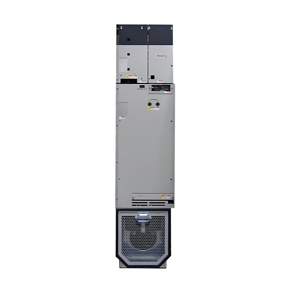
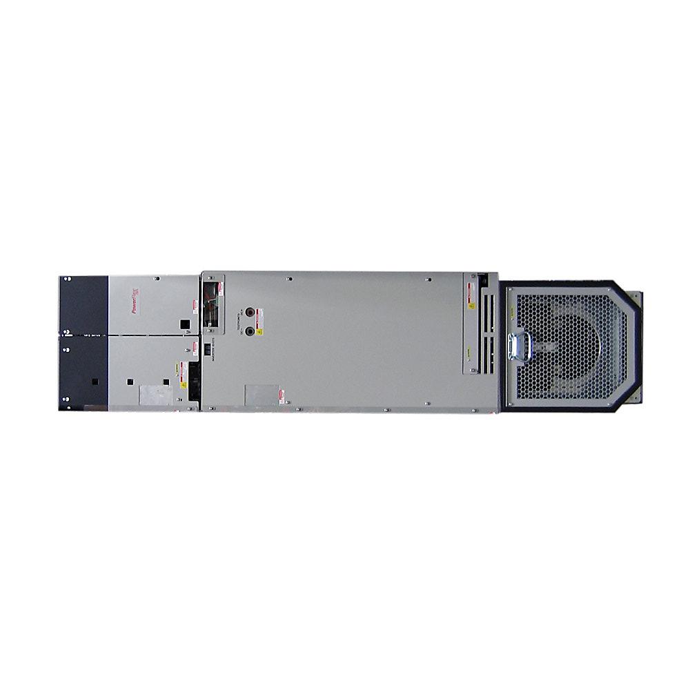
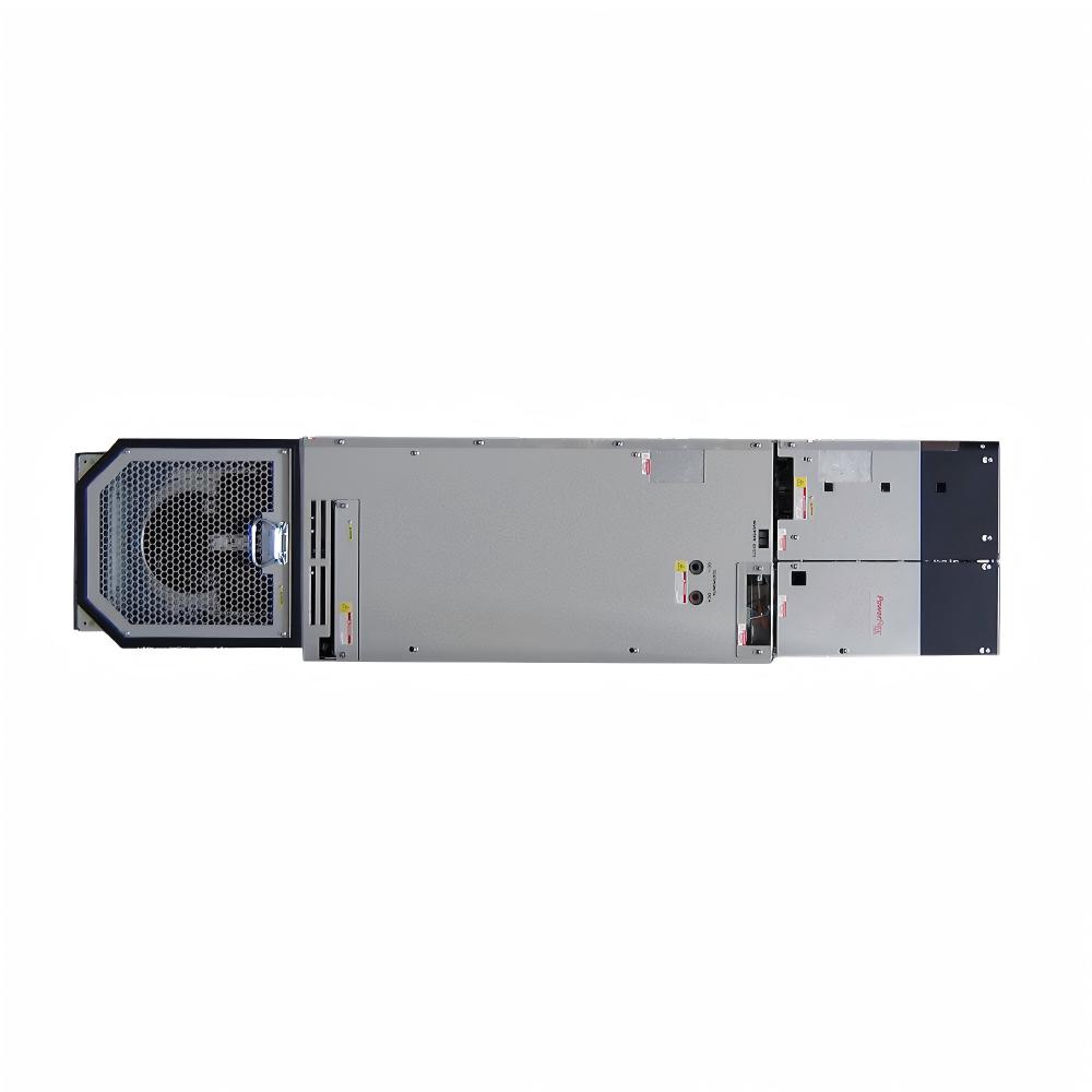
- Allen Bradley
- 20G14NF050JA0NNNNN
- PowerFlex AC Drive
- USA
- 2145 × 778 × 425 mm
- 286kg
- Xiamen, China
- New & In Stock
- T/T, PayPal, Western Union
- 1 Year
- 1-3 Working Days
- DHL, UPS, TNT, FedEx and EMS.
- 24-Hour Service
- COO
- 57
Our advantage

Global Logistics
We have a 10-year logistics and express cooperation agreement, so our products can be shipped to any place in the world.

Brand new and original
Our products are imported in bulk from the place of origin. Because of the cooperative relationship, our products are all original and 100% new.

24-hour service
We provide 7*24 hours service to our customers. We will be there whenever you need us.

Price advantage
All our products are priced very favorably because we have our own warehouse and supply.
| Company Information | |||
| [email protected] | |||
| Mobile | +8615980777398 | ||
| +8615980777398 | |||
| 15980777398 |
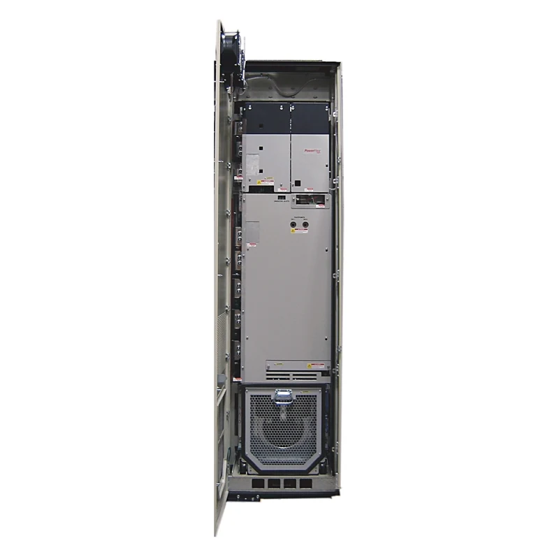
Allen-Bradley 20G14NF050JA0NNNNN PowerFlex 755 AC Drive – Technical Specifications, Product Introduction, Applications, Advantages, and Related Models
1. Product Overview
The Allen-Bradley 20G14NF050JA0NNNNN is a high-voltage industrial AC drive belonging to the PowerFlex 755 AC Drive family. It is designed for demanding variable-speed motor-control applications where high output power, reliable speed regulation, controlled acceleration and deceleration, and flexible industrial system integration are required.
This model is configured for 690 VAC, three-phase operation and provides a 50 A output rating. Its power rating is 45 kW under Normal Duty and 37 kW under Heavy Duty, making it suitable for a wide range of medium-to-large industrial motors and machines.
The drive uses a DC input with precharge architecture and is configured as an air-cooled, open-type Frame 6 drive. It includes a dynamic-braking transistor, is supplied in a filtered configuration with the CM jumper installed, and is configured without a local HIM in the standard catalog configuration.
The 20G14NF050JA0NNNNN is especially useful in industrial systems where a conventional standalone AC input arrangement is not the preferred architecture. Its DC-input configuration makes it suitable for common DC-bus systems and applications where several drives may be coordinated through a shared DC power architecture.
The combination of 690 VAC operation, 50 A output capability, 45 kW Normal Duty capacity, 37 kW Heavy Duty capacity, Frame 6 construction, and an integrated dynamic-braking transistor gives this model a strong position within the higher-power section of the 690 V PowerFlex 755 range.
2. Brand and Product Series
| Item | Specification |
|---|---|
| Brand | Allen-Bradley |
| Product Family | PowerFlex 755 AC Drive |
| Product Series | PowerFlex 755 |
| Product Type | Industrial AC Drive / Variable Frequency Drive |
| Catalog Number | 20G14NF050JA0NNNNN |
| Voltage Class | 690 VAC |
| Phase | Three Phase |
| Output Current | 50 A |
| Normal Duty Rating | 45 kW |
| Heavy Duty Rating | 37 kW |
| Input Configuration | DC Input with Precharge |
| Dynamic Braking | DB Transistor |
| Filtering | Filtered |
| CM Jumper | Installed |
| Cooling | Air Cooled / Forced Air |
| Frame Size | Frame 6 |
| Enclosure Type | Open Type |
| HIM Configuration | Blank / No HIM |
| Approx. Dimensions | 665.5 × 308 × 346.4 mm |
| Approx. Weight | ~14.5 kg* |
The catalog configuration identifies the model as a PowerFlex 755 AC drive with DC input and precharge, 50 A output, 45 kW Normal Duty, 37 kW Heavy Duty, 690 VAC three-phase operation, Frame 6 construction, filtered configuration, CM jumper installed, and an internal dynamic-braking transistor.
3. Detailed Technical Parameters
| Parameter | Specification |
|---|---|
| Model Number | 20G14NF050JA0NNNNN |
| Brand | Allen-Bradley |
| Series | PowerFlex 755 |
| Drive Category | AC Drive |
| Input Voltage Class | 690 VAC |
| Motor Voltage Class | 690 VAC |
| Phase | 3 Phase |
| Normal Duty Current | 50 A |
| Normal Duty Power | 45 kW |
| Heavy Duty Power | 37 kW |
| Input Type | DC Input with Precharge |
| Approximate DC Bus Class | High-voltage DC bus, approximately 932 VDC nominal class |
| Dynamic Braking | DB Transistor |
| Filtering | Filtered |
| CM Capacitor Jumper | Installed |
| Cooling | Forced Air |
| Frame | Frame 6 |
| Enclosure | IP20/IP00 Open Type |
| HIM | Blank / No HIM |
| Approx. Height | 665.5 mm |
| Approx. Width | 308 mm |
| Approx. Depth | 346.4 mm |
| Approx. Weight | ~14.5 kg* |
| Installation | Industrial Cabinet / Open-Type Installation |
| Typical Motor Application | Medium-to-Large Industrial Motors |
| Primary Architecture | DC Common-Bus / Industrial Drive System |
The 50 A configuration is associated with 45 kW Normal Duty and 37 kW Heavy Duty operation at 690 VAC. The exact catalog configuration also specifies forced-air cooling, Frame 6 construction, filtered operation, CM jumper installed, DC input with precharge, and an internal DB transistor.
*The dimensional and weight values above are provided as approximate engineering reference values for preliminary cabinet planning. The exact mechanical drawing and shipping documentation should be used for final installation dimensions, mounting locations, service clearances, and confirmed product weight.
4. Understanding the 20G14NF050JA0NNNNN Model Number
The catalog number contains configuration information that helps distinguish this drive from other PowerFlex 755 models.
| Model Portion | General Meaning |
|---|---|
| 20G | PowerFlex 755 AC Drive family |
| 14 | DC-input / common-bus configuration family |
| NF | 690 V / Frame 6 configuration group |
| 050 | 50 A output-current class |
| JA | Filtered configuration with dynamic-braking transistor |
| 0 | Configuration identifier |
| NNNNN | Standard catalog option configuration |
The 050 portion is particularly important because it identifies the 50 A current class. The JA configuration is also important because it indicates that the drive includes the internal dynamic-braking transistor, distinguishing it from the corresponding JN configuration without that transistor.
5. Product Construction
The 20G14NF050JA0NNNNN is designed as a high-power industrial drive rather than a small compact motor controller.
Its Frame 6 construction provides the physical platform required for the electrical components, cooling system, DC-link section, switching components, control electronics, and associated connection hardware required at this power level.
The drive uses forced-air cooling to remove heat generated during power conversion and motor operation.
For this reason, the surrounding cabinet design is important. The drive should have adequate airflow and sufficient clearance so that heated air can leave the drive area instead of circulating back through the cooling intake.
The open-type construction also means that the drive is normally installed as part of a larger electrical enclosure rather than treated as a complete outdoor or washdown enclosure.
6. 690 VAC Three-Phase Operation
One of the defining characteristics of the 20G14NF050JA0NNNNN is its 690 VAC three-phase voltage class.
A 690 V motor system is commonly used in higher-power industrial installations because increasing the voltage allows a given power level to be delivered at a lower current compared with a lower-voltage system.
Lower current can provide practical advantages in large installations, including reduced conductor current requirements, improved voltage-drop characteristics, and more manageable power distribution.
The 690 V architecture also makes this model suitable for large industrial machinery where motor power is too high for a small-drive platform.
7. 50 A Output Rating
The 50 A output rating is the central electrical characteristic of this model.
At 690 VAC, a 50 A drive provides a substantial amount of motor-control capacity.
The 50 A class is particularly useful for applications where the 30 A or 34 A models are no longer sufficient, but the larger 61 A or 82 A models would provide unnecessary capacity.
This makes the 20G14NF050JA0NNNNN a practical mid-to-upper-range selection within the 690 V Frame 6 family.
8. 45 kW Normal Duty Rating
The drive is rated at 45 kW for Normal Duty.
Normal Duty operation is generally associated with applications where the motor load is relatively predictable and the machine does not continuously require the more demanding overload characteristics associated with Heavy Duty operation.
Typical Normal Duty applications can include:
- Large centrifugal pumps.
- Industrial fans.
- Blowers.
- Cooling equipment.
- Conveyor systems with relatively stable loads.
- Process machinery with controlled acceleration.
- Continuous production equipment.
The 45 kW Normal Duty rating gives the drive a substantial operating range for industrial motors while retaining the flexibility of the PowerFlex 755 platform.
9. 37 kW Heavy Duty Rating
The Heavy Duty rating is 37 kW.
This lower kW rating compared with the 45 kW Normal Duty rating is intentional.
Heavy Duty applications generally place greater demands on the drive because the motor may need to provide higher torque during acceleration or withstand repeated overload conditions.
Typical Heavy Duty applications can include:
- Heavy conveyors.
- Material-handling machinery.
- Mixers.
- Crushers.
- Processing machines.
- High-inertia loads.
- Machinery with frequent starts and stops.
- Applications requiring significant acceleration torque.
Therefore, a 37 kW Heavy Duty rating does not mean the drive is less capable. Instead, it reflects a different thermal and overload operating condition.
10. DC Input with Precharge
The DC Input with Precharge configuration is one of the most important characteristics of this drive.
The drive is designed to receive power from a DC bus rather than using a conventional three-phase AC input arrangement at the drive’s input stage.
This makes it particularly useful in common-bus systems.
The precharge function is important because the drive contains DC-link capacitors. When a high-voltage DC bus is connected to an uncharged DC link, the initial charging current can be very high.
A controlled precharge sequence limits this initial charging current and allows the DC-link voltage to rise in a controlled manner.
This improves the electrical behavior of the system during startup and helps protect the DC-link components from uncontrolled charging current.
11. Common DC-Bus Applications
The DC-input architecture makes the 20G14NF050JA0NNNNN particularly interesting for multi-drive systems.
In a common DC-bus installation, multiple drive sections can share a DC power source.
This arrangement can be useful when several motors operate together and energy moves between accelerating and decelerating loads.
For example, one motor may be accelerating while another motor is decelerating.
The decelerating motor can return energy to the DC bus, while another motor may consume that energy.
This can make the overall energy architecture more efficient than treating every drive completely independently.
However, the DC bus, protection, precharge system, grounding, cable arrangement, bus capacity, and regenerative-energy management must be designed as a complete electrical system.
12. Integrated Dynamic-Braking Transistor
The JA configuration includes an internal dynamic-braking transistor.
This is one of the most important differences between the 20G14NF050JA0NNNNN and the corresponding JN configuration.
When a motor decelerates, its mechanical inertia can cause it to operate temporarily as a generator.
The resulting energy can increase the DC-bus voltage.
Dynamic braking provides a way to manage this excess energy by directing it into an appropriate braking resistor through the braking circuitry.
This is useful when fast deceleration is required and the machine has significant rotating inertia.
13. JA Versus JN Configuration
| Parameter | 20G14NF050JA0NNNNN | 20G14NF050JN0NNNNN |
|---|---|---|
| Voltage | 690 VAC | 690 VAC |
| Phase | 3 Phase | 3 Phase |
| Current | 50 A | 50 A |
| Normal Duty | 45 kW | 45 kW |
| Heavy Duty | 37 kW | 37 kW |
| Frame | 6 | 6 |
| Input | DC + Precharge | DC + Precharge |
| Filtering | Filtered | Filtered |
| CM Jumper | Installed | Installed |
| Dynamic Braking | DB Transistor | None |
| Cooling | Air Cooled | Air Cooled |
| HIM | No HIM | No HIM |
The main functional difference between the two configurations is the dynamic-braking transistor.
The JA version is the better choice when internal dynamic-braking capability is required.
The JN version is more appropriate when internal dynamic braking is not required or when another braking or regenerative-energy solution is used.
14. Filtered Configuration
The drive is configured as filtered with the CM jumper installed.
Filtering is important in industrial drive installations because power electronic switching can generate high-frequency electrical noise.
A properly designed filtered configuration can help control conducted electrical noise and support better electromagnetic compatibility within the overall installation.
However, filtering should not be considered a substitute for correct system wiring.
Motor cable selection, grounding, bonding, shielding, cable routing, cabinet layout, and installation practices all contribute to actual EMC performance.
15. Air-Cooled Design
The 20G14NF050JA0NNNNN uses forced-air cooling.
At this power level, heat management is a major part of the installation design.
The drive generates heat during normal operation due to switching losses, conduction losses, and internal electrical conversion.
The cabinet should therefore be designed around the drive’s cooling requirements.
Air passages should remain unobstructed.
The intake and exhaust areas should have enough clearance.
The cabinet should also prevent hot air from being recirculated directly back into the drive.
In dusty or harsh industrial environments, the enclosure and ventilation strategy should be designed carefully to prevent contamination from damaging the drive’s cooling system.
16. Open-Type Construction
The 20G14NF050JA0NNNNN is an open-type drive.
This provides flexibility for machine builders and industrial system designers because the drive can be installed inside a larger electrical cabinet designed specifically for the application.
The final cabinet can then be configured around:
- Main DC-bus equipment.
- Circuit protection.
- Control equipment.
- Communication equipment.
- Motor connections.
- Braking components.
- Cooling equipment.
- Maintenance access.
- Operator interface equipment.
This approach is particularly suitable for large automated machines and centralized industrial control cabinets.
17. Frame 6 Mechanical Platform
Frame 6 is a substantial mechanical platform designed for higher-power drive applications.
For preliminary engineering, the approximate reference dimensions are:
| Mechanical Parameter | Approximate Value |
|---|---|
| Model | 20G14NF050JA0NNNNN |
| Frame | Frame 6 |
| Height | 665.5 mm |
| Width | 308 mm |
| Depth | 346.4 mm |
| Approximate Weight | ~14.5 kg |
| Cooling | Forced Air |
| Construction | Open Type |
The values above are intended for preliminary layout work. Final cabinet fabrication should use the exact mechanical drawing for the particular hardware configuration.
Clearance for ventilation, cable routing, installation, inspection, and maintenance should also be considered rather than designing the cabinet around the drive’s external dimensions alone.
18. No HIM Configuration
The catalog configuration is supplied as Blank / No HIM.
The absence of a permanently installed Human Interface Module can be useful in centralized automation systems where operators and maintenance personnel normally interact with the drive through an external control system.
It can also provide a cleaner cabinet appearance and avoid installing a local interface that may not be required.
For commissioning and maintenance, the appropriate external programming, communication, or diagnostic method can be incorporated into the overall machine architecture.
19. Product Applications
Industrial Conveyor Systems
Large conveyor systems are a strong application area for this drive.
Conveyors can require substantial torque during startup, especially when the belt is already loaded.
Controlled acceleration helps reduce mechanical shock and can provide smoother machine operation.
The dynamic-braking capability is also useful where rapid or controlled stopping is required.
Heavy Material Handling
Material-handling equipment frequently experiences changing loads.
The 50 A output rating provides useful capacity for larger motors, while the Heavy Duty rating provides a basis for evaluating more demanding load conditions.
Applications may include large transfer conveyors, bulk-material equipment, production-line handling systems, and other industrial transport machinery.
Pumps
The drive can be used for larger industrial pumping systems.
Variable-speed operation allows the motor speed to be adjusted according to process demand.
This can provide more flexible flow control than simply operating the motor at one fixed speed.
For continuous processes, speed control can also help reduce unnecessary mechanical and electrical stress.
Fans and Blowers
Large industrial fans and blowers are another suitable application.
These systems often benefit from variable-speed operation because airflow requirements can change throughout the process.
The 45 kW Normal Duty capacity provides useful headroom for larger ventilation, cooling, combustion-air, and industrial air-handling systems.
Mixers and Process Equipment
Mixers and process machines can require significant starting torque.
Where the load profile fits within the Heavy Duty capability, the 20G14NF050JA0NNNNN can provide controlled acceleration and speed regulation.
The dynamic-braking transistor can also be valuable where the machine needs controlled deceleration.
Production Machinery
The drive can be used in automated production systems where motor speed needs to be coordinated with other machine functions.
Examples can include continuous processing equipment, large rotating machines, material-processing systems, and production machinery with changing speed requirements.
Common-Bus Multi-Drive Systems
The DC-input configuration makes this model particularly suitable for common-bus applications.
Where several drives operate together, a common DC bus can provide a centralized power architecture.
This can be especially useful when some motors are frequently accelerating while others are decelerating.
The exact system architecture must be engineered around the total DC-bus voltage, current, energy flow, precharge requirements, protection, and braking strategy.
20. Main Product Advantages
High 690 VAC Voltage Class
The 690 VAC rating makes the drive suitable for higher-power industrial motor systems.
For a given power level, a higher operating voltage can reduce current compared with a lower-voltage motor system.
This can simplify aspects of large power distribution and reduce voltage-drop concerns.
50 A Output Capability
The 50 A output rating provides a substantial amount of motor-control capacity.
It occupies a useful position between smaller 34 A and 46 A class drives and larger 61 A and 82 A class models.
This gives engineers flexibility when matching the drive to the motor’s actual current requirements.
45 kW Normal Duty Rating
The 45 kW Normal Duty rating makes the drive suitable for a broad range of industrial motors.
It provides sufficient capacity for many large pumps, fans, conveyors, blowers, and production machines.
37 kW Heavy Duty Rating
The 37 kW Heavy Duty rating allows the drive to be considered for applications with more demanding acceleration and overload requirements.
This makes the drive more versatile than a unit intended only for light or constant-load applications.
Integrated Dynamic Braking
The internal DB transistor is a significant advantage for applications requiring controlled deceleration.
It simplifies the drive configuration when dynamic braking is part of the machine design.
This is particularly useful for high-inertia loads and machines where stopping time must be controlled.
DC Input and Common-Bus Compatibility
The DC-input configuration is valuable for centralized DC power systems.
It allows the drive to become part of a broader common-bus architecture rather than operating as an isolated AC-input drive.
Filtered Configuration
The filtered configuration with CM jumper installed provides a useful foundation for installations where electrical noise and EMC need to be carefully managed.
Frame 6 Platform
Frame 6 provides a robust platform for higher-power applications and offers multiple neighboring current ratings within the same product family.
This can simplify the selection process when a project contains motors of different sizes.
Open-Type Flexibility
The open construction allows the drive to be integrated into a custom industrial cabinet.
This is useful for OEM machinery, process equipment, centralized drive cabinets, and large automation systems.
21. Installation and Cabinet Design Considerations
The installation environment should be considered carefully because the drive is an open-type, air-cooled device.
The cabinet should provide adequate space around the drive for cooling airflow.
Power cables should be routed so that they do not obstruct the ventilation path.
The cabinet should also provide enough space for the DC-bus connections, motor output connections, control wiring, communication connections, and maintenance access.
The braking system should also be considered during cabinet design.
If dynamic braking is used, the braking resistor and associated wiring must be installed according to the complete system requirements.
The resistor generates heat during braking, so its location should be selected carefully.
It should not be installed where its heat can significantly increase the drive’s ambient temperature.
22. Motor Matching
Motor selection should be based on actual motor nameplate information rather than simply matching the motor’s kW value to the drive’s maximum rating.
The following should be checked:
- Motor voltage.
- Motor full-load current.
- Motor power.
- Motor frequency.
- Motor speed.
- Load torque.
- Acceleration time.
- Deceleration time.
- Starting frequency.
- Overload requirements.
- Duty cycle.
- Ambient operating conditions.
For a Normal Duty application, the 45 kW rating is the principal reference.
For a Heavy Duty application, the 37 kW rating should be used.
The motor’s full-load current should always remain within the appropriate drive capability after considering the complete operating profile.
23. Dynamic-Braking Application Considerations
The integrated DB transistor makes this model particularly attractive when the machine has significant inertia.
Examples include large rotating equipment, conveyors, high-speed machinery, and machines that must stop within a controlled period.
When a motor decelerates, kinetic energy is returned to the electrical system.
If the energy cannot be absorbed elsewhere, the DC-bus voltage can increase.
Dynamic braking provides a controlled path for dissipating this energy through a suitable braking resistor.
The braking resistor must be selected according to the machine’s actual braking energy, braking frequency, duty cycle, and required stopping performance.
24. Five Closely Related Models in the Same Series
The following models are useful alternatives within the 690 V PowerFlex 755 family.
| Model | Voltage | Current | Normal Duty | Heavy Duty | Frame | Dynamic Braking | Input |
|---|---|---|---|---|---|---|---|
| 20G14NF030JA0NNNNN | 690 VAC | 30 A | 22 kW | 18.5 kW | 6 | DB Transistor | DC + Precharge |
| 20G14NF034JA0NNNNN | 690 VAC | 34 A | 30 kW | 22 kW | 6 | DB Transistor | DC + Precharge |
| 20G14NF046JA0NNNNN | 690 VAC | 46 A | 37 kW | 30 kW | 6 | DB Transistor | DC + Precharge |
| 20G14NF061JA0NNNNN | 690 VAC | 61 A | 55 kW | 45 kW | 6 | DB Transistor | DC + Precharge |
| 20G14NF082JA0NNNNN | 690 VAC | 82 A | 75 kW | 55 kW | 6 | DB Transistor | DC + Precharge |
These models form a practical progression around the 50 A target model, allowing the drive to be selected according to motor current, power, and overload requirements. The 690 V family includes progressively larger current and power ratings while retaining the same general PowerFlex 755 architecture.
25. Comparison of Related Models
20G14NF030JA0NNNNN
The 30 A model is suitable when the required motor current is substantially below 50 A.
Its 22 kW Normal Duty and 18.5 kW Heavy Duty ratings make it appropriate for smaller machines within the same 690 V family.
It is a good choice when the 50 A capacity would otherwise be excessive.
20G14NF034JA0NNNNN
The 34 A model provides 30 kW Normal Duty and 22 kW Heavy Duty capacity.
It is positioned between the 30 A and 46 A models and can be useful when the motor’s current requirements fall within this intermediate range.
20G14NF046JA0NNNNN
The 46 A model is the closest smaller alternative to the 50 A target model.
With 37 kW Normal Duty and 30 kW Heavy Duty capacity, it can be an economical alternative when the application does not require the additional current capacity of the 50 A model.
20G14NF061JA0NNNNN
The 61 A model moves to the next larger capacity level.
It provides 55 kW Normal Duty and 45 kW Heavy Duty capability.
This model is appropriate when the motor current is approaching or exceeding the practical range of the 50 A model.
20G14NF082JA0NNNNN
The 82 A version provides 75 kW Normal Duty and 55 kW Heavy Duty capacity.
It is intended for substantially larger industrial motors and machines.
26. Five Related Allen-Bradley Models for Broader Comparison
| Model | Voltage | Current | Normal Duty | Heavy Duty | Frame | Dynamic Braking | Input |
|---|---|---|---|---|---|---|---|
| 20G14NF020JA0NNNNN | 690 VAC | 20 A | 15 kW | 11 kW | 6 | DB Transistor | DC + Precharge |
| 20G14NF030JA0NNNNN | 690 VAC | 30 A | 22 kW | 18.5 kW | 6 | DB Transistor | DC + Precharge |
| 20G14NF034JA0NNNNN | 690 VAC | 34 A | 30 kW | 22 kW | 6 | DB Transistor | DC + Precharge |
| 20G14NF061JA0NNNNN | 690 VAC | 61 A | 55 kW | 45 kW | 6 | DB Transistor | DC + Precharge |
| 20G14NF082JA0NNNNN | 690 VAC | 82 A | 75 kW | 55 kW | 6 | DB Transistor | DC + Precharge |
These models provide a broader selection around the 50 A target drive. The 20 A and 30 A versions are suitable for smaller motors, while the 61 A and 82 A versions provide additional capacity for larger systems.
27. Model Selection by Motor Power
| Approximate Application Size | Suggested Model | Normal Duty | Heavy Duty | Current |
|---|---|---|---|---|
| Small 690 V industrial motor | 20G14NF020JA0NNNNN | 15 kW | 11 kW | 20 A |
| Medium 690 V industrial motor | 20G14NF030JA0NNNNN | 22 kW | 18.5 kW | 30 A |
| Medium-high 690 V motor | 20G14NF034JA0NNNNN | 30 kW | 22 kW | 34 A |
| Large 690 V motor | 20G14NF046JA0NNNNN | 37 kW | 30 kW | 46 A |
| Larger 690 V motor | 20G14NF050JA0NNNNN | 45 kW | 37 kW | 50 A |
| High-capacity 690 V motor | 20G14NF061JA0NNNNN | 55 kW | 45 kW | 61 A |
| Very high-capacity 690 V motor | 20G14NF082JA0NNNNN | 75 kW | 55 kW | 82 A |
This progression illustrates why the 50 A model is a useful selection point. It provides more capacity than the 46 A version while remaining smaller than the 61 A and 82 A classes.
28. Advantages for OEM Machine Builders
For OEM machine builders, the 20G14NF050JA0NNNNN offers several practical advantages.
The 690 V architecture makes it suitable for high-power machinery.
The 50 A current rating provides useful design capacity.
The 45 kW Normal Duty rating covers a broad range of industrial motors.
The 37 kW Heavy Duty rating provides a separate selection point for more demanding machines.
The integrated dynamic-braking transistor simplifies applications that require controlled braking.
The DC-input configuration allows the drive to be incorporated into a centralized DC-bus architecture.
The open-type construction also provides flexibility when designing the machine’s electrical cabinet.
29. Advantages for Industrial Automation Systems
In an automated production system, the drive is not simply responsible for changing motor speed.
It may also form part of the machine’s broader motion, process, safety, energy, and diagnostic architecture.
The PowerFlex 755 platform is designed for this type of industrial application.
The 20G14NF050JA0NNNNN can therefore be considered when a machine requires coordinated motor operation, controlled acceleration and deceleration, and integration into a larger industrial automation system.
Its common-bus capability is particularly useful when multiple drives operate within the same electrical architecture.
30. Maintenance Considerations
Regular maintenance should focus on airflow, electrical connections, cooling components, and the overall cabinet environment.
The cooling path should remain clean and unobstructed.
Accumulated dust can reduce cooling performance and increase operating temperature.
Electrical connections should be inspected according to the maintenance schedule for the installation.
The DC-bus system should be treated as a high-voltage energy-storage system, and appropriate shutdown and discharge procedures must be followed before maintenance.
Dynamic-braking components should also be inspected in applications with frequent braking.
31. Application Advantages of Dynamic Braking
The JA configuration becomes particularly valuable when the machine has frequent deceleration cycles.
For example, a conveyor may need to stop quickly after reaching the end of a production cycle.
A high-inertia rotating machine may need controlled stopping to prevent overspeed or excessive mechanical stress.
A material-handling system may require repeated acceleration and deceleration.
In these cases, the integrated DB transistor provides an important part of the braking architecture.
The actual braking resistor must still be properly selected for the required braking energy and duty cycle.
32. Product Selection Checklist
Before selecting the 20G14NF050JA0NNNNN for a project, engineers should confirm the following:
| Selection Item | Check |
|---|---|
| Motor Voltage | Confirm compatibility with 690 VAC system |
| Motor Current | Confirm motor current is within drive capability |
| Motor Power | Evaluate against 45 kW ND / 37 kW HD |
| Duty Type | Determine Normal Duty or Heavy Duty |
| Acceleration | Confirm required starting torque |
| Deceleration | Determine braking requirements |
| Dynamic Braking | Required; internal DB transistor is included |
| DC Bus | Confirm suitable DC-bus architecture |
| Precharge | Confirm system precharge arrangement |
| Cooling | Provide adequate forced-air ventilation |
| Cabinet | Allow sufficient installation clearance |
| EMC | Confirm grounding, bonding, filtering, and cable layout |
| Environment | Confirm temperature, dust, moisture, and contamination conditions |
| Motor Cable | Select according to voltage, current, distance, and installation |
| Maintenance | Provide sufficient service access |
This checklist helps prevent a common mistake in drive selection: choosing a drive solely from the motor’s nominal kW rating without considering current, duty, acceleration, braking, and the electrical architecture.
33. Key Product Parameters at a Glance
| Parameter | Value |
|---|---|
| Model | 20G14NF050JA0NNNNN |
| Brand | Allen-Bradley |
| Series | PowerFlex 755 |
| Product Type | AC Drive |
| Voltage | 690 VAC |
| Phase | Three Phase |
| Current | 50 A |
| Normal Duty | 45 kW |
| Heavy Duty | 37 kW |
| Input | DC Input with Precharge |
| Dynamic Braking | DB Transistor |
| Filtering | Filtered |
| CM Jumper | Installed |
| Cooling | Forced Air |
| Frame | Frame 6 |
| Enclosure | Open Type |
| HIM | Blank / No HIM |
| Approx. Height | 665.5 mm |
| Approx. Width | 308 mm |
| Approx. Depth | 346.4 mm |
| Approx. Weight | ~14.5 kg |
| Main Application | Industrial Motor Control |
| Typical Architecture | DC Common-Bus / Industrial Drive System |
The exact product configuration identifies the 20G14NF050JA0NNNNN as a 50 A, 45 kW Normal Duty, 37 kW Heavy Duty, 690 VAC three-phase PowerFlex 755 drive with DC input and precharge, filtered configuration, CM jumper installed, Frame 6 construction, and an internal DB transistor.
34. Overall Product Assessment
The Allen-Bradley 20G14NF050JA0NNNNN is a high-capacity industrial AC drive designed for demanding 690 V motor-control applications.
Its combination of 50 A output current, 45 kW Normal Duty capacity, 37 kW Heavy Duty capacity, DC input with precharge, integrated dynamic-braking transistor, filtered configuration, forced-air cooling, and Frame 6 construction gives it considerable flexibility for industrial applications.
One of its most valuable characteristics is the combination of DC-bus architecture and dynamic-braking capability.
The DC-input design makes the drive suitable for common-bus applications, while the internal DB transistor makes it suitable for machines where controlled dissipation of regenerative energy is required during deceleration.
The 690 VAC rating also makes it a strong candidate for larger industrial motors.
Compared with the smaller 30 A, 34 A, and 46 A models, the 50 A configuration provides additional current and power capacity.
Compared with the larger 61 A and 82 A models, it offers a more compact selection when the motor requirements fall within the 50 A range.
The JA configuration is especially important when braking is required. If the application does not need an internal dynamic-braking transistor, the corresponding JN configuration can be considered instead.
From an engineering perspective, the 20G14NF050JA0NNNNN should be evaluated as part of the complete motor-control system rather than as an isolated drive.
Motor voltage, motor current, duty cycle, overload requirements, acceleration, deceleration, braking energy, DC-bus architecture, precharge, cabinet cooling, EMC, grounding, cable selection, and maintenance access all contribute to the final performance of the installation.
For industrial machinery requiring approximately 50 A at 690 VAC, with 45 kW Normal Duty or 37 kW Heavy Duty capacity, and where dynamic braking and DC common-bus operation are important, the 20G14NF050JA0NNNNN is a strong and versatile PowerFlex 755 configuration.