

ProductPRODUCT
Featured products








Contact Us
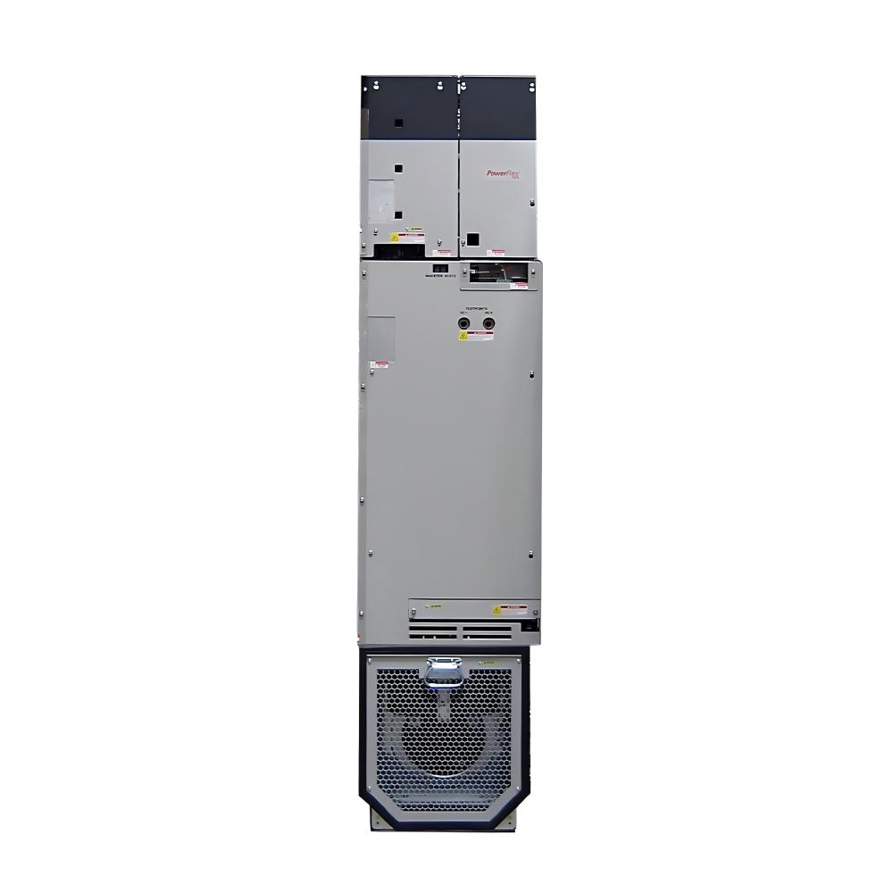
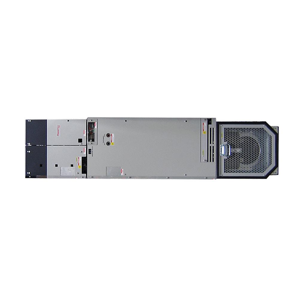
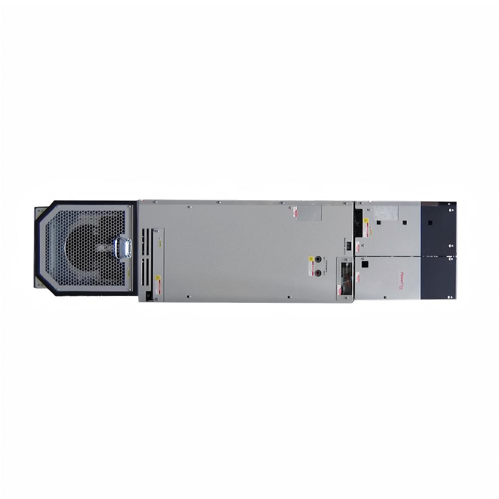
- Allen Bradley
- 20G14NF046JN0NNNNN
- PowerFlex AC Drive
- USA
- 2145 × 778 × 425 mm
- 286kg
- Xiamen, China
- New & In Stock
- T/T, PayPal, Western Union
- 1 Year
- 1-3 Working Days
- DHL, UPS, TNT, FedEx and EMS.
- 24-Hour Service
- COO
- 53
Our advantage

Global Logistics
We have a 10-year logistics and express cooperation agreement, so our products can be shipped to any place in the world.

Brand new and original
Our products are imported in bulk from the place of origin. Because of the cooperative relationship, our products are all original and 100% new.

24-hour service
We provide 7*24 hours service to our customers. We will be there whenever you need us.

Price advantage
All our products are priced very favorably because we have our own warehouse and supply.
| Company Information | |||
| [email protected] | |||
| Mobile | +8615980777398 | ||
| +8615980777398 | |||
| 15980777398 |
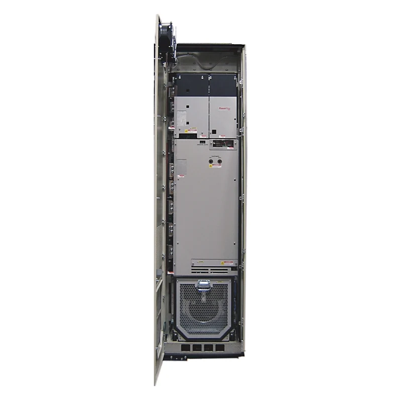
Allen-Bradley 20G14NF046JN0NNNNN PowerFlex 755 AC Drive – Detailed Product Introduction, Specifications, Applications, Advantages, and Related Models
1. Product Overview
The Allen-Bradley 20G14NF046JN0NNNNN is a high-power PowerFlex 755 AC Drive designed for demanding industrial motor-control applications where stable speed regulation, reliable torque control, flexible system integration, and robust operation are required.
This model belongs to the PowerFlex 755 AC Drive family and is configured as an air-cooled, open-type, Frame 6 drive for 690 VAC three-phase systems. It is rated at 46 A, with a 37 kW Normal Duty rating and a 30 kW Heavy Duty rating. The drive uses a DC input with precharge, includes filtering with the CM jumper installed, and does not include an internal dynamic-braking transistor.
The 20G14NF046JN0NNNNN is particularly suitable for large industrial machines and common-bus installations where the DC bus is supplied separately and controlled through a suitable precharge arrangement. Its combination of a high-voltage DC bus architecture, substantial current capacity, and PowerFlex 755 control platform makes it appropriate for applications that demand dependable continuous operation rather than simple low-cost motor starting.
The model is also supplied with a blank configuration without a HIM, which means the drive does not include the integral Human Interface Module as part of this catalog configuration. This can be advantageous in systems where commissioning and parameter management are performed through the control network or through external engineering tools rather than through a permanently mounted local keypad.
2. Brand and Product Series
| Item | Information |
|---|---|
| Brand | Allen-Bradley |
| Product Family | PowerFlex 755 AC Drive |
| Series | PowerFlex 750-Series |
| Product Type | AC Drive / Variable Frequency Drive |
| Catalog Number | 20G14NF046JN0NNNNN |
| Cooling Method | Forced Air / Air Cooled |
| Frame Size | Frame 6 |
| Installation Type | Open Type |
| Voltage Class | 690 VAC, Three Phase |
| Input Configuration | DC Input with Precharge |
| Dynamic Braking | None |
| Filtering | Filtered, CM Jumper Installed |
| HIM | Blank / No HIM |
| Lifecycle Status | Active Mature |
The defining feature of the JN0 configuration is the absence of an internal dynamic-braking transistor. The filtering configuration is specified as filtered with the CM jumper installed.
3. Main Technical Parameters
| Parameter | Specification |
|---|---|
| Model Number | 20G14NF046JN0NNNNN |
| Brand | Allen-Bradley |
| Series | PowerFlex 755 |
| Drive Type | AC Drive |
| Voltage | 690 VAC |
| Phase | 3 Phase |
| Output Current – Normal Duty | 46 A continuous |
| Normal Duty Power | 37 kW |
| Normal Duty 1-Minute Current | 50.6 A |
| Normal Duty 3-Second Current | 69 A |
| Output Current – Heavy Duty | 34 A continuous |
| Heavy Duty Power | 30 kW |
| Heavy Duty 1-Minute Current | 51 A |
| Heavy Duty 3-Second Current | 69 A |
| Input Type | DC Input with Precharge |
| Nominal DC Input Class | Approximately 932 VDC |
| Dynamic Braking | None |
| EMC / Filtering | Filtered |
| CM Jumper | Installed |
| Cooling | Forced Air |
| Enclosure | IP20/IP00, NEMA/UL Open Type |
| Frame | Frame 6 |
| HIM | Blank / No HIM |
| Approx. Dimensions H × W × D | 665.5 × 308 × 346.4 mm |
| Approx. Weight | ~14.5 kg* |
The 46 A rating is associated with 37 kW Normal Duty operation and 30 kW Heavy Duty operation. The published selection data gives 50.6 A for the one-minute Normal Duty overload and 69 A for the three-second Normal Duty overload. For Heavy Duty operation, the corresponding continuous current is 34 A, with 51 A for one minute and 69 A for three seconds.
*The dimensional and weight figures above should be treated as engineering reference values rather than a substitute for the exact mechanical drawing supplied with the individual unit. Frame 6 mechanical configurations can vary according to the exact hardware arrangement, enclosure treatment, and accessories.
4. Model Number Identification
The catalog number contains a considerable amount of configuration information. Understanding the model structure is useful when selecting a replacement or comparing neighboring PowerFlex 755 models.
| Model Section | Meaning |
|---|---|
| 20G | PowerFlex 755 AC Drive family designation |
| 14 | DC-input/common-bus configuration family |
| N | 690 VAC voltage class family |
| F | Frame 6 configuration |
| 046 | 46 A output-current rating |
| J | Filtered configuration with CM jumper installed |
| N | No internal dynamic-braking transistor |
| 0 | Configuration identifier |
| NNNNN | Standard catalog configuration/options |
The most important selection point for this particular model is the combination of 046, J, and N. The 046 portion identifies the 46 A class, while the J configuration corresponds to the filtered arrangement with the CM jumper installed. The N braking configuration means that an internal dynamic-braking transistor is not provided.
5. 690 VAC Three-Phase Design
The 20G14NF046JN0NNNNN is designed for the 690 VAC three-phase class, making it suitable for high-voltage industrial motor systems where higher motor voltages are preferred for larger power levels.
At 690 VAC, a 37 kW motor can be operated with considerably lower current than an equivalent motor at a much lower voltage. This can help with conductor sizing, voltage drop, cabinet distribution, and overall system power architecture.
The 690 VAC rating also places this model within the higher-voltage portion of the PowerFlex 755 selection range. The 46 A model occupies a useful middle position in the 690 V Frame 6 lineup, sitting between the 34 A and 50 A versions.
6. 46 A Output Rating
The 46 A continuous Normal Duty output rating is one of the most important characteristics of this drive.
For Normal Duty applications, the drive provides:
- 46 A continuous output.
- 50.6 A for a one-minute overload period.
- 69 A for a three-second overload period.
- 37 kW Normal Duty rating.
For Heavy Duty applications, the drive is rated:
- 34 A continuous output.
- 51 A for a one-minute overload period.
- 69 A for a three-second overload period.
- 30 kW Heavy Duty rating.
This dual-rating approach is important when selecting a drive for an actual machine. A motor application with relatively smooth loading may be able to use the 37 kW Normal Duty rating, while a machine with high starting torque, frequent acceleration, shock loading, or demanding overload conditions may need to be evaluated against the 30 kW Heavy Duty rating.
The motor should therefore not be selected simply by comparing the drive’s maximum kW number with the motor nameplate. The actual load profile, acceleration requirements, overload duration, duty cycle, and motor current should all be considered.
7. Normal Duty and Heavy Duty Operation
Normal Duty and Heavy Duty ratings allow the same drive platform to address different mechanical loads.
Normal Duty
The Normal Duty rating is appropriate for applications where the motor generally operates with moderate load torque and where overload demand is comparatively limited.
The 37 kW Normal Duty rating provides a substantial power level for applications such as pumps, fans, conveyors, process machinery, and other equipment with relatively predictable load profiles.
Heavy Duty
The Heavy Duty rating is lower at 30 kW, but the drive is designed to tolerate a more demanding overload profile.
This rating is more relevant when the machine requires greater torque during acceleration or experiences significant load changes. Typical examples include heavily loaded conveyors, material-handling systems, mixers, crushers, certain hoisting-related machinery, and process equipment with substantial starting resistance.
The distinction between 37 kW Normal Duty and 30 kW Heavy Duty is therefore not a weakness. It is a deliberate way of expressing the thermal and overload capability of the same power converter under different operating conditions.
8. DC Input with Precharge
One of the most distinctive features of the 20G14NF046JN0NNNNN is its DC input with precharge configuration.
Unlike a conventional AC-input drive that receives three-phase AC directly at its input rectifier, a DC-input/common-bus drive receives power from an established DC bus architecture.
The precharge function is important because the drive’s DC-link capacitors can otherwise present a very large initial charging current when connected directly to a high-voltage DC bus.
A controlled precharge sequence limits this initial current and allows the DC link to reach the appropriate operating voltage in a controlled manner.
This arrangement is especially useful in systems where multiple drives share a common DC bus or where regenerative energy can be transferred between drives rather than being dissipated independently.
For example, during a deceleration event, one drive may generate energy while another drive on the same DC bus is accelerating. A properly engineered common-bus system can make better use of this energy.
This is one reason the 20G14NF046JN0NNNNN can be attractive for coordinated multi-drive industrial machinery.
9. No Internal Dynamic-Braking Transistor
The JN0 configuration does not include an internal dynamic-braking transistor. This is a major difference between the JN and JA versions of the same 46 A class.
| Feature | 20G14NF046JN0NNNNN | 20G14NF046JA0NNNNN |
|---|---|---|
| Voltage | 690 VAC | 690 VAC |
| Current | 46 A | 46 A |
| Normal Duty | 37 kW | 37 kW |
| Heavy Duty | 30 kW | 30 kW |
| Frame | Frame 6 | Frame 6 |
| DC Input | Yes | Yes |
| Filtering | Filtered | Filtered |
| CM Jumper | Installed | Installed |
| Internal DB Transistor | None | Yes |
| Cooling | Air Cooled | Air Cooled |
The JA version is the better choice when an internal braking transistor is required. The JN version is more appropriate when braking is not required internally, when the application uses another braking architecture, or when regenerative/common-bus energy management is handled elsewhere.
10. Filtering and CM Jumper Configuration
The 20G14NF046JN0NNNNN is specified as filtered with the CM jumper installed.
This configuration is useful in installations where electromagnetic compatibility and common-mode behavior are important design considerations.
Filtering can help control conducted electrical noise and support cleaner interaction between the drive and the surrounding electrical system.
The CM jumper configuration should nevertheless be considered during system installation. Grounding, motor-cable construction, cable length, shielding, cabinet layout, bonding, and other installation practices all influence actual EMC performance.
The drive should therefore be treated as one part of the overall electrical system rather than as an isolated component.
11. Air-Cooled Frame 6 Construction
The drive uses forced-air cooling and belongs to Frame 6.
Forced-air cooling is a practical solution for a drive in this power range because significant heat is generated by semiconductor switching, power conversion, and associated internal components.
Good cabinet ventilation is consequently important.
The cooling-air path should remain unobstructed, and the surrounding cabinet should be designed so that hot exhaust air does not simply circulate back toward the drive’s intake.
Dust, oil mist, moisture, and corrosive industrial atmospheres should also be considered when selecting the final enclosure arrangement.
The catalog configuration is an open-type IP20/IP00 design, so it should not be interpreted as a complete standalone weatherproof enclosure. The final system enclosure must provide the environmental protection required by the installation.
12. Approximate Dimensions and Weight
The 20G14NF046JN0NNNNN uses a Frame 6 mechanical platform.
For preliminary cabinet planning, an approximate reference envelope is:
| Mechanical Parameter | Approximate Value |
|---|---|
| Model | 20G14NF046JN0NNNNN |
| Frame | Frame 6 |
| Height | 665.5 mm |
| Width | 308 mm |
| Depth | 346.4 mm |
| Approximate Weight | 14.5 kg |
| Installation | Open Type |
| Cooling | Forced Air |
These figures are intended for preliminary engineering, enclosure layout, and space planning. The exact dimensional drawing should always be used for final mounting-hole locations, clearances, cable entry, ventilation requirements, and shipping-weight calculations.
13. Human Interface Module Configuration
The catalog configuration is supplied without a HIM, meaning the local Human Interface Module is blank/not included.
This configuration can be useful in centralized automation systems where the drive is normally commissioned through the plant control architecture rather than through a permanent local operator interface.
It can also reduce unnecessary hardware on installations where local keypad operation is not required.
For commissioning, parameter adjustment, diagnostics, and maintenance, the appropriate external communication or programming method should be selected according to the complete control-system design.
14. Product Applications
The 20G14NF046JN0NNNNN is intended for industrial applications requiring a relatively high-power, high-voltage motor drive with common-bus capability.
Conveyor Systems
Large conveyors are one of the most natural applications for this class of drive.
A conveyor can have substantial starting torque requirements, particularly when loaded material is already present on the belt.
The drive can provide controlled acceleration and deceleration, reducing mechanical shock compared with direct-on-line starting.
For longer conveyor systems, coordinated drive control can also improve process stability and reduce unnecessary mechanical stress.
Pumps
The drive can be used with industrial pumping systems where variable speed is required.
Changing pump speed can provide useful process control and may reduce unnecessary energy consumption compared with running the pump continuously at full speed and regulating flow through mechanical means.
The 690 VAC architecture is particularly appropriate for larger industrial pumping systems where motors operate at higher voltage levels.
Fans and Blowers
Large fans and blowers are another suitable application.
These machines often have relatively predictable load characteristics, making them good candidates for the Normal Duty rating when the actual motor current and mechanical load remain within the appropriate operating range.
Variable-speed operation can also provide useful process control in ventilation, combustion-air, cooling, and industrial air-handling systems.
Material Handling
Material-handling equipment can require substantial torque during acceleration and may experience rapidly changing loads.
The 20G14NF046JN0NNNNN can be considered for applications where controlled motor acceleration, stable speed regulation, and coordinated operation are important.
Process Machinery
The drive is also suitable for various continuous-process machines where motor speed must be controlled accurately and reliably.
Potential examples include processing lines, industrial production equipment, large rotating machines, and other systems where the motor is part of a larger automated process.
Common DC-Bus Systems
The DC-input configuration makes this model particularly interesting for common-bus architectures.
Multiple drives can be connected to a shared DC power system when the system is engineered appropriately.
This architecture can provide benefits in systems where drives frequently accelerate and decelerate because energy can potentially move through the common DC bus rather than being treated independently at each drive.
The exact common-bus architecture, protection, precharge arrangement, grounding, bus capacity, and regenerative-energy management must be designed for the complete system.
15. Main Product Advantages
15.1 High-Voltage 690 VAC Platform
The 690 VAC rating makes the drive suitable for higher-power industrial motors and systems where lower current at a given power level is beneficial.
This can help simplify large motor power distribution compared with using lower-voltage architectures at equivalent power.
15.2 37 kW Normal Duty Capacity
The 37 kW Normal Duty rating gives the drive a useful capacity for medium-to-large industrial motor applications.
The 46 A current rating provides additional flexibility when matching the drive to a motor.
15.3 30 kW Heavy Duty Capability
The 30 kW Heavy Duty rating allows the same drive to be considered for applications with more demanding overload requirements.
This gives engineers another way to select the drive according to the actual mechanical load instead of looking only at the nominal motor horsepower or kW rating.
15.4 Common-Bus Compatibility
The DC-input with precharge configuration is particularly valuable in coordinated multi-drive systems.
Where a common DC bus is part of the machine architecture, multiple drive sections can be designed around the same DC power infrastructure.
15.5 No Unnecessary Internal Braking Hardware
The absence of an internal dynamic-braking transistor is an advantage when the application does not require one.
This avoids selecting a braking-enabled configuration when braking is not part of the system design.
It also provides a clear distinction between the JN and JA configurations.
15.6 Filtered Configuration
The filtered configuration with the CM jumper installed provides a useful starting point for applications where EMC considerations are important.
The final EMC performance will still depend heavily on system installation practices.
15.7 Open-Type Flexibility
The open-type design allows the drive to be incorporated into a larger industrial cabinet or electrical enclosure.
This can be advantageous for OEM machine builders and industrial system integrators that prefer to design the overall enclosure themselves.
15.8 Frame 6 Platform
Frame 6 provides a substantial mechanical and electrical platform suitable for the 690 V power range.
The common frame architecture across several current ratings also simplifies the process of comparing adjacent models.
16. Installation Considerations
When installing the 20G14NF046JN0NNNNN, cabinet engineering should be treated as an important part of the drive selection.
Adequate clearance must be provided around the drive for cooling airflow, wiring, inspection, and maintenance.
The forced-air cooling path should not be blocked by cable ducts, neighboring equipment, filters, or cabinet structures.
The drive should also be installed in an environment compatible with its open-type construction.
Cable routing is another important consideration. Motor cables, DC-bus conductors, control wiring, feedback cables, and communication wiring should be arranged to minimize unwanted electrical coupling.
Grounding and bonding should be planned as part of the complete system design.
17. Motor Selection
The motor should be selected according to its actual nameplate current, voltage, frequency, power, speed, duty cycle, and mechanical load.
For a Normal Duty application, the 37 kW rating is the relevant reference point.
For a Heavy Duty application, the 30 kW rating should be used instead.
It is not recommended to select a motor solely from the drive’s maximum advertised kW rating without checking the actual motor current and overload requirements.
For example, a 37 kW motor may be appropriate in a relatively smooth Normal Duty application, while a mechanically demanding machine may require a lower motor power selection if it must operate under the Heavy Duty rating.
18. Dynamic Braking Selection Considerations
Because the 20G14NF046JN0NNNNN has no internal dynamic-braking transistor, engineers should evaluate the machine’s deceleration requirements carefully.
If the motor must decelerate rapidly while carrying a high-inertia load, the DC bus can rise because the motor becomes a generator during deceleration.
Depending on the system architecture, that energy may be transferred to another part of the common DC bus, managed through a regenerative arrangement, or handled through another braking solution.
If the application specifically requires a braking transistor integrated into the drive, the corresponding JA configuration should be considered instead.
This makes the JN0 and JA0 configurations functionally different even though their main voltage, current, power, and frame ratings are similar.
19. Five Closely Related Models in the Same Series
The following models are useful comparison points because they remain within the 690 V PowerFlex 755 family and cover nearby current and power ratings.
| Model | Voltage | Current | Normal Duty | Heavy Duty | Frame | Dynamic Braking | Input |
|---|---|---|---|---|---|---|---|
| 20G14NF030JN0NNNNN | 690 VAC | 30 A | 22 kW | 18.5 kW | 6 | None | DC + Precharge |
| 20G14NF034JN0NNNNN | 690 VAC | 34 A | 30 kW | 22 kW | 6 | None | DC + Precharge |
| 20G14NF050JN0NNNNN | 690 VAC | 50 A | 45 kW | 37 kW | 6 | None | DC + Precharge |
| 20G14NF061JN0NNNNN | 690 VAC | 61 A | 55 kW | 45 kW | 6 | None | DC + Precharge |
| 20G14NF082JN0NNNNN | 690 VAC | 82 A | 75 kW | 55 kW | 6 | None | DC + Precharge |
These models follow the same 690 V common-bus selection structure, with the main difference being output-current and power capacity. The 30 A, 34 A, 46 A, 50 A, 61 A, and 82 A ratings form a useful progression when sizing a drive around the actual motor and machine load.
20. Comparison of the Five Closely Related Models
20G14NF030JN0NNNNN
The 30 A model is a logical choice when the motor load is below the 46 A capacity of the target drive.
It provides 22 kW Normal Duty and 18.5 kW Heavy Duty capacity, making it appropriate for smaller machines while retaining the same general 690 V DC-input architecture.
20G14NF034JN0NNNNN
The 34 A model sits directly below the 46 A model in the same family.
Its 30 kW Normal Duty and 22 kW Heavy Duty ratings make it useful when a 30 kW-class motor is required but the additional capacity of the 46 A model is unnecessary.
20G14NF050JN0NNNNN
The 50 A model is the nearest larger step above the 46 A version.
It provides 45 kW Normal Duty and 37 kW Heavy Duty capacity.
This makes it a strong candidate when the motor current is too close to the 46 A limit or when additional capacity is desirable for future expansion.
20G14NF061JN0NNNNN
The 61 A model increases capacity further to 55 kW Normal Duty and 45 kW Heavy Duty.
It is more appropriate for larger motors and heavier industrial machinery.
20G14NF082JN0NNNNN
The 82 A model provides 75 kW Normal Duty and 55 kW Heavy Duty capability.
It is suitable when the system has moved beyond the 46 A and 50 A class and requires substantially greater motor power.
21. Five Commonly Selected Allen-Bradley Models for Comparison
The following models provide a broader comparison across the same product family, including different power levels and one lower-voltage example.
| Model | Voltage | Current | Normal Duty | Heavy Duty | Frame | Dynamic Braking | Input |
|---|---|---|---|---|---|---|---|
| 20G14NF020JA0NNNNN | 690 VAC | 20 A | 15 kW | 11 kW | 6 | DB Transistor | DC + Precharge |
| 20G14NF030JA0NNNNN | 690 VAC | 30 A | 22 kW | 18.5 kW | 6 | DB Transistor | DC + Precharge |
| 20G14NF034JA0NNNNN | 690 VAC | 34 A | 30 kW | 22 kW | 6 | DB Transistor | DC + Precharge |
| 20G14NF050JA0NNNNN | 690 VAC | 50 A | 45 kW | 37 kW | 6 | DB Transistor | DC + Precharge |
| 20G14FD077JA0NNNNN | 480 VAC | 77 A | 60 HP | 50 HP | 5 | DB Transistor | DC + Precharge |
These examples show how the PowerFlex 755 family extends across different current levels and voltage classes. The first four are 690 V examples, while the 480 V model illustrates a lower-voltage alternative within the same broad drive family.
22. Target Model Versus the JA Version
For replacement and engineering work, one of the most useful comparisons is between the target 20G14NF046JN0NNNNN and 20G14NF046JA0NNNNN.
| Parameter | 20G14NF046JN0NNNNN | 20G14NF046JA0NNNNN |
|---|---|---|
| Voltage | 690 VAC | 690 VAC |
| Current | 46 A | 46 A |
| Normal Duty | 37 kW | 37 kW |
| Heavy Duty | 30 kW | 30 kW |
| Frame | 6 | 6 |
| Cooling | Air Cooled | Air Cooled |
| Input | DC + Precharge | DC + Precharge |
| Filtering | Filtered | Filtered |
| CM Jumper | Installed | Installed |
| Dynamic Braking | None | DB Transistor |
| HIM | No HIM | No HIM |
The electrical power capacity is essentially the same, but the braking configuration is different. The JN version is therefore not automatically interchangeable with the JA version in every application.
If the existing machine relies on the internal braking transistor, the braking configuration must be checked before selecting the JN version. Conversely, if the original system does not require internal braking, the JN configuration may be a suitable choice.
23. Why the 20G14NF046JN0NNNNN Is a Useful Industrial Drive
The biggest strength of this model is its balance between power capacity and system flexibility.
At 46 A and 37 kW Normal Duty, it is powerful enough for a substantial range of industrial machinery while remaining within the Frame 6 platform.
Its 690 VAC rating makes it suitable for higher-voltage industrial motors.
Its DC-input architecture makes it especially useful in common-bus systems.
Its filtered configuration provides a useful foundation for EMC-conscious installations.
Its JN0 configuration removes the internal dynamic-braking transistor, making the model appropriate for applications where braking is not required internally or where another braking or regenerative strategy is used.
The open-type construction also gives system designers freedom to integrate the drive into a larger electrical cabinet rather than forcing the complete machine design around a standalone enclosure.
24. Recommended Selection Strategy
When selecting the 20G14NF046JN0NNNNN, the following sequence is practical.
First, confirm the motor voltage is compatible with the 690 VAC system.
Second, check the motor’s full-load current against the drive’s continuous current rating.
Third, determine whether the machine should be evaluated using the 37 kW Normal Duty rating or the 30 kW Heavy Duty rating.
Fourth, examine the acceleration and deceleration profile.
Fifth, determine whether the machine requires internal dynamic braking.
Sixth, confirm that the plant uses a suitable DC-bus and precharge architecture.
Seventh, check the cabinet dimensions, cooling arrangement, wiring space, and maintenance access.
Finally, confirm the exact mechanical and electrical configuration against the unit’s catalog documentation before placing the drive into service.
25. Summary of Key Specifications
| Key Item | Specification |
|---|---|
| Model | 20G14NF046JN0NNNNN |
| Brand | Allen-Bradley |
| Series | PowerFlex 755 |
| Product Type | AC Drive |
| Voltage | 690 VAC |
| Phase | Three Phase |
| Current | 46 A |
| Normal Duty | 37 kW |
| Heavy Duty | 30 kW |
| Normal Duty 1-Minute | 50.6 A |
| Normal Duty 3-Second | 69 A |
| Heavy Duty 1-Minute | 51 A |
| Heavy Duty 3-Second | 69 A |
| Input | DC Input with Precharge |
| Dynamic Braking | None |
| Filtering | Filtered |
| CM Jumper | Installed |
| Cooling | Forced Air |
| Enclosure | IP20/IP00 Open Type |
| Frame | Frame 6 |
| HIM | Blank / No HIM |
| Approx. Dimensions | 665.5 × 308 × 346.4 mm |
| Approx. Weight | ~14.5 kg |
| Primary Application | Industrial motor control |
| Special Strength | High-voltage common-bus drive architecture |
The published 690 V selection data confirms the 46 A model’s 37 kW Normal Duty and 30 kW Heavy Duty ratings, while the exact product configuration identifies the unit as a filtered, DC-input-with-precharge, Frame 6 drive without an internal dynamic-braking transistor.
26. Final Assessment
The Allen-Bradley 20G14NF046JN0NNNNN PowerFlex 755 AC Drive is a substantial industrial drive intended for high-voltage, high-power motor-control systems.
Its 690 VAC three-phase rating, 46 A output capacity, 37 kW Normal Duty rating, 30 kW Heavy Duty rating, DC input with precharge, filtered configuration, forced-air cooling, and Frame 6 construction make it well suited to demanding industrial installations.
The absence of an internal dynamic-braking transistor is an important part of the product definition. Rather than being viewed simply as a missing feature, it should be considered a deliberate configuration choice. It makes the model particularly suitable for systems where dynamic braking is not required internally, where braking is handled through another part of the system, or where a common DC-bus architecture provides an alternative energy-management strategy.
For applications requiring an integrated braking transistor, the closely related JA configuration should be evaluated instead.
From a system-engineering perspective, the 20G14NF046JN0NNNNN is best suited to installations where the drive is treated as part of a complete electrical and automation architecture. Correct motor sizing, DC-bus design, precharge, cooling, grounding, EMC practices, cabinet ventilation, overload selection, and deceleration requirements all have a direct effect on the final performance of the installation.
For a 690 V industrial system requiring approximately 46 A of Normal Duty output and 37 kW of Normal Duty motor capacity, this model represents a strong and practical PowerFlex 755 configuration, particularly where common-bus operation and external energy-management strategies are important.