

ProductPRODUCT
Featured products








Contact Us
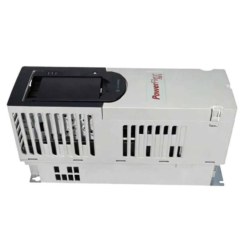
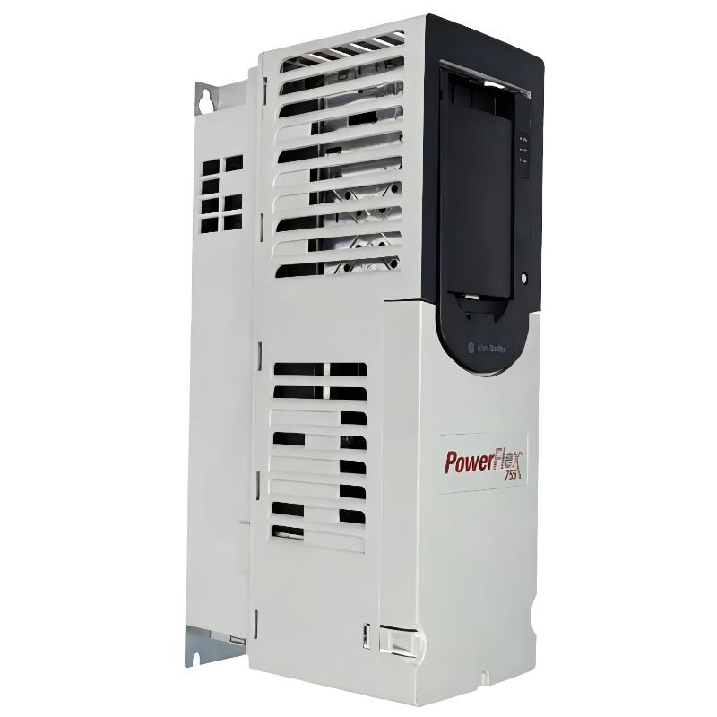
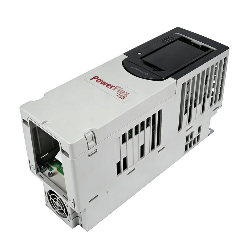
- Allen Bradley
- 20G11TC567JN0NNNNN
- PowerFlex AC Drive
- USA
- 2,145 mm × 778 mm × 425 mm
- 286kg
- Xiamen, China
- New & In Stock
- T/T, PayPal, Western Union
- 1 Year
- 1-3 Working Days
- DHL, UPS, TNT, FedEx and EMS.
- 24-Hour Service
- COO
- 61
Our advantage

Global Logistics
We have a 10-year logistics and express cooperation agreement, so our products can be shipped to any place in the world.

Brand new and original
Our products are imported in bulk from the place of origin. Because of the cooperative relationship, our products are all original and 100% new.

24-hour service
We provide 7*24 hours service to our customers. We will be there whenever you need us.

Price advantage
All our products are priced very favorably because we have our own warehouse and supply.
| Company Information | |||
| [email protected] | |||
| Mobile | +8615980777398 | ||
| +8615980777398 | |||
| 15980777398 |
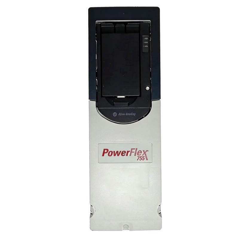
20G11TC567JN0NNNNN – Detailed Product Description, Technical Parameters, Applications, Advantages and Related Models
1. Product Overview
The 20G11TC567JN0NNNNN is a high-power industrial AC variable frequency drive belonging to the PowerFlex 755 series.
It is designed for controlling large three-phase AC motors in industrial applications where adjustable speed, controlled acceleration, controlled deceleration, process coordination and industrial network communication are required.
This model is a substantial Frame 8 drive, with a 567 A output current rating, a 315 kW normal-duty rating, a 355 kW light-duty rating, and a 250 kW heavy-duty rating.
The drive uses forced-air cooling and is intended for installation as an open-type industrial drive. It is equipped with embedded EtherNet/IP communication, making it suitable for integration into automated production lines and larger plant control systems.
A particularly important characteristic of this exact model is the J configuration, which indicates that the common-mode capacitor jumper is installed.
The model is therefore closely related to the corresponding A-version configuration, but the A and J versions should not simply be treated as interchangeable because their common-mode capacitor configurations are different.
2. Brand and Product Series
| Item | Description |
|---|---|
| Brand | Allen-Bradley |
| Product family | PowerFlex |
| Series | PowerFlex 755 |
| Product type | Industrial AC Variable Frequency Drive |
| Drive category | High-power AC drive |
| Cooling method | Forced air |
| Construction | Open type |
| Frame | Frame 8 |
| Input | Three-phase AC |
| Communication | Embedded EtherNet/IP |
| Main function | Variable-speed control of AC motors |
| Typical power range | Large industrial motor applications |
The PowerFlex 755 series is designed for applications requiring more functionality and power capability than a basic compact variable-frequency drive.
The 20G11TC567JN0NNNNN is one of the higher-power configurations within this product family and is intended primarily for large industrial machinery.
3. Model Number
| Parameter | Specification |
|---|---|
| Model | 20G11TC567JN0NNNNN |
| Product family | PowerFlex |
| Series | PowerFlex 755 |
| Drive type | AC Variable Frequency Drive |
| Voltage class | 400 VAC |
| Input phase | 3 phase |
| Rated current | 567 A |
| Light-duty power | 355 kW |
| Normal-duty power | 315 kW |
| Heavy-duty power | 250 kW |
| Frame | Frame 8 |
| Cooling | Forced air |
| Filtering | Filtered |
| CM capacitor jumper | Installed |
| Dynamic braking | None |
| HIM | Blank / No HIM |
| Communication | Embedded EtherNet/IP |
| Enclosure style | Open type |
| Application category | Large industrial motor control |
4. Main Electrical Parameters
| Electrical Parameter | Specification |
|---|---|
| Model | 20G11TC567JN0NNNNN |
| Input voltage | 400 VAC class |
| Input phase | 3 phase |
| Output current | 567 A |
| Light-duty current | 567 A class |
| Normal-duty current | 567 A |
| Heavy-duty current | 472 A |
| Light-duty power | 355 kW |
| Normal-duty power | 315 kW |
| Heavy-duty power | 250 kW |
| Frame | 8 |
| Cooling | Forced air |
| Input configuration | AC input with precharge / DC terminals |
| Filtering | Filtered |
| Common-mode capacitor jumper | Installed |
| Dynamic braking | None |
| Communication | Embedded EtherNet/IP |
| HIM | Blank / No HIM |
| Enclosure | Open type |
| Motor application | Large three-phase AC motors |
The most important sizing value is generally the motor current rather than the motor power alone.
For a real installation, the motor nameplate current should be compared with the appropriate drive duty rating.
A 315 kW motor does not necessarily have exactly the same current requirement in every installation because motor efficiency, power factor, voltage, frequency and motor design can all affect operating current.
5. Duty Ratings
The drive provides different power capabilities depending on the load-duty category.
| Duty | Current | Approximate Power |
|---|---|---|
| Light Duty | 567 A class | 355 kW |
| Normal Duty | 567 A | 315 kW |
| Heavy Duty | 472 A | 250 kW |
The difference between these ratings is important when selecting a drive for a particular machine.
A fan or centrifugal pump may have a relatively smooth load profile and can often be considered under a lighter-duty rating.
A conveyor, mixer or high-inertia machine can place much greater demands on the drive during acceleration and operation.
For such applications, the heavy-duty rating should be considered carefully.
6. Product Introduction
The 20G11TC567JN0NNNNN is essentially the power-control center between an industrial electrical supply and a large AC motor.
Instead of supplying the motor directly with fixed-frequency AC power, the drive electronically controls the voltage and frequency supplied to the motor.
This provides several important functions.
The motor can start gradually instead of receiving a sudden full-voltage starting condition.
The operating speed can be adjusted according to the production process.
Acceleration and deceleration can be programmed.
The motor can communicate operating information to the plant control system.
Faults and operating conditions can be monitored.
The overall machine can therefore operate in a much more controlled manner than a simple fixed-speed motor arrangement.
7. How the Drive Works
A simplified power path can be represented as follows:
Three-Phase AC Power
↓
Input Power Section
↓
Rectifier / DC Bus
↓
Inverter Power Section
↓
Variable-Frequency AC Output
↓
Three-Phase Motor
The control system provides the operating command.
For example:
PLC / Controller
↓
EtherNet/IP
↓
20G11TC567JN0NNNNN
↓
Motor
↓
Pump / Fan / Conveyor / Blower / Machine
The drive continuously manages motor operation according to the configured control parameters.
8. 400 VAC Three-Phase Configuration
The 20G11TC567JN0NNNNN is a 400 VAC, three-phase drive configuration.
This voltage class is widely used in industrial installations based on 380–400 V three-phase power systems.
The drive is therefore particularly relevant to industrial facilities using 400 V-class electrical distribution.
The exact incoming voltage, transformer arrangement, grounding system, protection equipment and motor voltage should be verified during project engineering.
9. 567 Amp Current Rating
The 567 A rating is one of the most important characteristics of this model.
A current rating of this magnitude places the drive in the high-power industrial category.
It is intended for motors that require hundreds of amperes rather than the relatively small current levels associated with compact machine drives.
Applications can include:
- Large pumps
- Large fans
- Heavy conveyors
- Large blowers
- Process machinery
- Material-handling equipment
- Industrial mixers
- Large rotating equipment
The motor’s actual nameplate current should always be checked before final drive selection.
10. 315 kW Normal-Duty Rating
The normal-duty rating is approximately:
315 kW
This makes the model appropriate for large industrial motors in the 315 kW class when the application’s duty requirements match the normal-duty rating.
Typical examples include large pumps, fans, conveyors and process machinery.
The 315 kW rating should not be interpreted as a universal maximum motor size.
Motor current, overload requirements, acceleration requirements and environmental conditions must also be considered.
11. 355 kW Light-Duty Rating
The light-duty rating is approximately:
355 kW
This provides additional motor power capacity for applications where the load profile does not require the same overload capability as a heavy-duty application.
Typical examples can include:
- Centrifugal pumps
- Centrifugal fans
- Ventilation systems
- Large blowers
- Cooling systems
- Water circulation systems
The actual application should determine which duty rating is appropriate.
12. 250 kW Heavy-Duty Rating
The heavy-duty rating is approximately:
250 kW / 472 A
Heavy-duty applications may have:
- High starting torque
- High mechanical inertia
- Frequent acceleration
- Frequent deceleration
- High continuous load
- Significant mechanical resistance
Examples include:
- Heavy conveyors
- Mixers
- Material-handling machines
- Processing equipment
- High-inertia rotating machinery
The heavy-duty rating should be used when the application requires the additional overload capability associated with this duty category.
13. Common-Mode Capacitor Jumper Installed
The J configuration is significant.
For this model, the common-mode capacitor jumper is installed.
| Model Configuration | CM Capacitor Jumper |
|---|---|
| 20G11TC567JN0NNNNN | Installed |
| 20G11TC567AN0NNNNN | Removed |
The common-mode capacitor configuration can affect the electrical behavior of the drive with respect to grounding and common-mode currents.
Therefore, the A and J configurations should be selected according to the electrical system and installation requirements.
14. Embedded EtherNet/IP
The drive includes embedded EtherNet/IP communication.
This is particularly useful in automated industrial environments.
A controller can exchange information with the drive, including:
- Start command
- Stop command
- Speed reference
- Direction
- Enable
- Reset
- Drive status
- Output frequency
- Motor current
- Fault status
- Warning status
- Diagnostic information
This allows the drive to become an integrated part of a plant-wide automation system.
15. No Dynamic Braking
The model is specified with:
Dynamic Braking: None
This is an important consideration for machines with large rotating inertia.
When a motor decelerates, mechanical energy can return toward the drive’s DC bus.
If the machine requires rapid deceleration or frequent braking, the overall braking strategy must be evaluated.
Applications requiring high braking performance may require an appropriate external braking arrangement or another system-level solution.
This is especially important for:
- Large conveyors
- High-inertia rollers
- Large fans with significant rotating mass
- Centrifuges
- Heavy rotating equipment
16. Cooling System
The 20G11TC567JN0NNNNN uses forced-air cooling.
At a power rating of several hundred kilowatts, the amount of heat generated by power electronics can be significant.
Consequently, ventilation and thermal management are essential.
The installation should provide suitable airflow around the drive.
Particular attention should be paid to:
- Ambient temperature
- Airflow direction
- Cabinet ventilation
- Cooling-fan condition
- Dust accumulation
- Hot-air recirculation
- Cabinet heat dissipation
The drive should not be installed where the cooling airflow is blocked.
17. Physical Dimensions
Because this is a large Frame 8 drive, the equipment requires considerably more installation space than compact drives.
For planning purposes, the drive assembly is approximately in the following size range:
| Mechanical Parameter | Approximate Value |
|---|---|
| Model | 20G11TC567JN0NNNNN |
| Frame | Frame 8 |
| Approx. height | 2,145 mm |
| Approx. width | 778 mm |
| Approx. depth | 425 mm |
| Installation type | Open type |
| Cooling | Forced air |
| Approx. weight (kg) | 286 kg |
These figures should be regarded as approximate planning values for the drive assembly.
A complete electrical cabinet, disconnect system, bus system, cooling arrangement, incoming protection and other accessories can result in substantially greater overall dimensions and weight.
For a final mechanical drawing, the exact configuration should be checked against the equipment drawing applicable to the particular installation.
18. Weight
The approximate drive assembly weight is:
286 kg
This is a significant mechanical load.
Installation planning should therefore consider:
- Transportation
- Lifting
- Floor loading
- Cabinet structure
- Mounting hardware
- Maintenance access
- Replacement procedures
A lifting method should be planned before the equipment reaches the installation location.
The shipping package may weigh more than the bare drive assembly because of packaging and additional components.
19. Product Applications
19.1 Large Pump Systems
The drive is well suited to large industrial pumping systems.
Potential applications include:
- Water transfer
- Process-water circulation
- Cooling-water systems
- Industrial pumping
- Wastewater systems
- Large circulation pumps
- Utility pumps
Variable-speed control allows pump output to be adjusted according to process demand.
This can reduce unnecessary operation at maximum speed.
19.2 Large Fan Systems
Large fans can consume substantial electrical power when operated continuously at high speed.
The drive can provide:
- Adjustable airflow
- Controlled acceleration
- Controlled speed
- Centralized monitoring
- Process-based speed control
Typical applications include:
- Industrial ventilation
- Exhaust systems
- Furnace systems
- Cooling systems
- Process-air systems
- Large ventilation installations
19.3 Large Conveyor Systems
Large conveyors often require powerful motors and controlled acceleration.
The drive can help reduce mechanical shock during startup.
Potential applications include:
- Bulk material conveyors
- Mining conveyors
- Production-line conveyors
- Material-transfer systems
- Heavy-duty handling systems
19.4 Blower Systems
Large industrial blowers may require several hundred kilowatts.
The drive can regulate blower speed according to pressure or airflow requirements.
This is useful in process plants where air demand changes throughout the production cycle.
19.5 Compressors
Large compressors can require substantial motor power.
Where variable-speed operation is appropriate, the drive can provide controlled acceleration and adjustable operating speed.
The final selection should consider compressor torque characteristics and the manufacturer’s motor requirements.
19.6 Mixers
Large mixers may experience substantial resistance during startup.
Controlled acceleration can help reduce sudden mechanical stress.
Applications include:
- Chemical processing
- Material mixing
- Industrial production
- Large process mixers
- Heavy-duty mixing equipment
19.7 Material-Handling Machinery
The drive can be used for large material-handling systems where motor speed must be coordinated with the overall process.
Examples include:
- Transfer systems
- Rollers
- Feed systems
- Industrial handling equipment
- Large production machinery
20. Main Product Advantages
| Advantage | Description |
|---|---|
| High current capacity | 567 A class output capability |
| High power capability | Up to approximately 355 kW under light-duty conditions |
| Large industrial frame | Frame 8 construction |
| Network integration | Embedded EtherNet/IP |
| Variable-speed operation | Motor speed can be adjusted to process requirements |
| Controlled acceleration | Reduces sudden mechanical stress |
| Controlled deceleration | Provides programmable stopping characteristics |
| Industrial diagnostics | Operating and fault information can be monitored |
| Forced-air cooling | Suitable for high-power applications |
| Flexible application range | Pumps, fans, conveyors, blowers and process equipment |
| Filtered configuration | Supports electrical-noise management |
| J configuration | Common-mode capacitor jumper installed |
21. Energy-Saving Potential
One major advantage of variable-frequency drives is the ability to operate a motor at the speed actually required by the process.
This is particularly useful for centrifugal pumps and fans.
For example, if a pump does not need to operate at maximum output, reducing its speed can significantly change its operating power requirement.
Possible benefits include:
- Reduced unnecessary energy consumption
- Better process control
- Reduced throttling losses
- Lower mechanical stress
- Reduced wear
- Improved operating flexibility
Actual energy savings depend heavily on the machine’s load characteristics.
22. Motor Compatibility
The motor should be selected and checked using its complete nameplate information.
| Motor Parameter | Importance |
|---|---|
| Rated voltage | Must correspond to the drive output range |
| Rated current | Critical for drive sizing |
| Rated power | Used together with current and duty |
| Rated frequency | Required for configuration |
| Rated speed | Determines operating characteristics |
| Power factor | Affects current requirements |
| Efficiency | Affects operating current |
| Service factor | Important for overload evaluation |
| Motor type | Determines appropriate control method |
| Load inertia | Important for acceleration |
| Starting torque | Important for heavy-duty applications |
| Speed range | Determines application suitability |
The motor should therefore not be selected only by matching its kW value.
23. Installation Requirements
A Frame 8 drive requires considerably more installation planning than a small VFD.
Important considerations include:
- Incoming power cables
- Motor output cables
- Grounding
- Control wiring
- Network wiring
- Cable bending radius
- Cabinet ventilation
- Cooling airflow
- Maintenance clearance
- Lifting access
- Floor loading
- Electrical protection
- Environmental conditions
The installation should provide sufficient space for maintenance personnel to safely inspect and service the equipment.
24. Typical Control Architecture
A typical industrial system can be arranged as follows:
Main Electrical Supply
↓
Circuit Protection
↓
20G11TC567JN0NNNNN
↓
315 kW-Class AC Motor
↓
Industrial Machine
At the control level:
Industrial Controller
↓
EtherNet/IP
↓
20G11TC567JN0NNNNN
The controller can provide speed commands and operating instructions while receiving drive status and diagnostic information.
25. Maintenance Considerations
| Maintenance Item | Recommended Attention |
|---|---|
| Cooling fans | Check operation and unusual noise |
| Air passages | Keep free from obstruction |
| Cabinet ventilation | Verify airflow |
| Power connections | Inspect according to maintenance procedures |
| Grounding | Check connection integrity |
| Motor cables | Inspect insulation and terminals |
| Network cables | Check communication connections |
| Fault history | Look for repeated faults |
| Drive temperature | Monitor abnormal temperature |
| Cabinet cleanliness | Prevent excessive dust |
| Mechanical mounting | Check for looseness |
| Environment | Monitor temperature and humidity |
Because this is a large high-power drive, preventive maintenance can be particularly important.
Repeated drive faults should not simply be reset without determining the underlying cause.
26. Common Troubleshooting Areas
| Problem | Areas to Check |
|---|---|
| Motor does not start | Enable, start command, active fault |
| Drive overload | Motor load, current rating, acceleration time |
| Overcurrent during acceleration | Load torque, acceleration time, motor data |
| DC-bus overvoltage | Deceleration time, regeneration, braking system |
| Drive overheating | Cooling fans, airflow, ambient temperature |
| Communication fault | Network cable, address and controller configuration |
| Incorrect speed | Speed reference and scaling |
| Repeated trips | Electrical and mechanical conditions |
| Electrical noise | Grounding, shielding, cable routing |
| Motor vibration | Motor condition and control configuration |
27. Five Recommended Same-Series or Closely Related Models
The following models are useful alternatives within the same PowerFlex 755 high-power family.
| Model | Voltage | Light-Duty | Normal-Duty | Heavy-Duty | Frame | Cooling | Approx. Weight (kg) |
|---|---|---|---|---|---|---|---|
| 20G11TC460JN0NNNNN | 400 VAC | Approx. 315 kW | Approx. 250 kW | Approx. 200 kW | 8 | Forced air | Approx. 286 |
| 20G11TC540JN0NNNNN | 400 VAC | Approx. 315 kW | Approx. 315 kW | Approx. 250 kW | 8 | Forced air | Approx. 286 |
| 20G11TC567AN0NNNNN | 400 VAC | 355 kW | 315 kW | 250 kW | 8 | Forced air | Approx. 286 |
| 20G11TC650JN0NNNNN | 400 VAC | Approx. 400 kW | Approx. 355 kW | Approx. 315 kW | 8 | Forced air | Approx. 286 |
| 20G11TC750JN0NNNNN | 400 VAC | Approx. 450 kW | Approx. 400 kW | Approx. 315 kW | 8 | Forced air | Approx. 286 |
The exact current and duty selection should be confirmed against the intended motor and load profile before purchasing or replacing equipment.
28. Recommended Alternative No. 1
20G11TC460JN0NNNNN
This is a lower-current configuration in the same general 400 VAC PowerFlex 755 family.
| Parameter | Specification |
|---|---|
| Model | 20G11TC460JN0NNNNN |
| Series | PowerFlex 755 |
| Voltage | 400 VAC class |
| Phase | 3 phase |
| Frame | 8 |
| Light-duty power | Approx. 315 kW |
| Normal-duty power | Approx. 250 kW |
| Heavy-duty power | Approx. 200 kW |
| Cooling | Forced air |
| Filtering | Filtered |
| CM jumper | Installed |
| Communication | Embedded EtherNet/IP |
| Dynamic braking | None |
| Approx. dimensions | 2145 × 778 × 425 mm class |
| Approx. weight (kg) | 286 kg |
This model can be considered when the required motor current is lower than the 567 A requirement.
29. Recommended Alternative No. 2
20G11TC540JN0NNNNN
This model provides a slightly lower current capacity than the subject model.
| Parameter | Specification |
|---|---|
| Model | 20G11TC540JN0NNNNN |
| Series | PowerFlex 755 |
| Voltage | 400 VAC class |
| Phase | 3 phase |
| Frame | 8 |
| Light-duty power | Approx. 315 kW |
| Normal-duty power | Approx. 315 kW |
| Heavy-duty power | Approx. 250 kW |
| Cooling | Forced air |
| Filtering | Filtered |
| CM jumper | Installed |
| Communication | Embedded EtherNet/IP |
| Dynamic braking | None |
| Approx. dimensions | 2145 × 778 × 425 mm class |
| Approx. weight (kg) | 286 kg |
This is a useful choice when the motor’s actual current requirement is below the 567 A rating.
30. Recommended Alternative No. 3
20G11TC567AN0NNNNN
This is the closest configuration variant of the subject model.
| Parameter | Specification |
|---|---|
| Model | 20G11TC567AN0NNNNN |
| Series | PowerFlex 755 |
| Voltage | 400 VAC class |
| Phase | 3 phase |
| Output current | 567 A |
| Light-duty power | 355 kW |
| Normal-duty power | 315 kW |
| Heavy-duty power | 250 kW |
| Frame | 8 |
| Cooling | Forced air |
| Filtering | Filtered |
| CM jumper | Removed |
| Communication | Embedded EtherNet/IP |
| Dynamic braking | None |
| Approx. dimensions | 2145 × 778 × 425 mm class |
| Approx. weight (kg) | 286 kg |
The principal difference is the common-mode capacitor jumper configuration.
The subject J version has the jumper installed, while the A version has it removed.
31. Recommended Alternative No. 4
20G11TC650JN0NNNNN
This is a higher-capacity configuration.
| Parameter | Specification |
|---|---|
| Model | 20G11TC650JN0NNNNN |
| Series | PowerFlex 755 |
| Voltage | 400 VAC class |
| Phase | 3 phase |
| Frame | 8 |
| Light-duty power | Approx. 400 kW |
| Normal-duty power | Approx. 355 kW |
| Heavy-duty power | Approx. 315 kW |
| Cooling | Forced air |
| Filtering | Filtered |
| CM jumper | Installed |
| Communication | Embedded EtherNet/IP |
| Dynamic braking | None |
| Approx. dimensions | 2145 × 778 × 425 mm class |
| Approx. weight (kg) | 286 kg |
This model is appropriate for applications requiring more current capacity than the 567 A configuration.
32. Recommended Alternative No. 5
20G11TC750JN0NNNNN
This is another higher-capacity configuration in the same general family.
| Parameter | Specification |
|---|---|
| Model | 20G11TC750JN0NNNNN |
| Series | PowerFlex 755 |
| Voltage | 400 VAC class |
| Phase | 3 phase |
| Frame | 8 |
| Light-duty power | Approx. 450 kW |
| Normal-duty power | Approx. 400 kW |
| Heavy-duty power | Approx. 315 kW |
| Cooling | Forced air |
| Filtering | Filtered |
| CM jumper | Installed |
| Communication | Embedded EtherNet/IP |
| Dynamic braking | None |
| Approx. dimensions | 2145 × 778 × 425 mm class |
| Approx. weight (kg) | 286 kg |
This model is more suitable when a larger motor and higher current requirement are involved.
33. Five Same-Brand Popular Models for Different Applications
The following models represent different power levels and are useful for comparison when the motor size is significantly smaller than the 315 kW class.
| Model | Series | Voltage Class | Current Class | Approx. Motor Power | Typical Application | Approx. Dimensions | Weight (kg) |
|---|---|---|---|---|---|---|---|
| 20G11GD014AA0NNNNN | PowerFlex 755 | 480 V class | 14 A | 10 HP class | Pumps, fans, conveyors | Small-frame | Approx. 8–12 |
| 20G11GD022AA0NNNNN | PowerFlex 755 | 480 V class | 22 A | 15 HP class | General industrial machinery | Small-frame | Approx. 8–12 |
| 20G11GD027AA0NNNNN | PowerFlex 755 | 480 V class | 27 A | 20 HP class | Pumps, conveyors, fans | Small-frame | Approx. 12–15 |
| 25B-D6P0N104 | PowerFlex 525 | 480 V class | 6 A | 3 HP class | Compact machinery | Compact | Approx. 2–3 |
| 25B-D011N104 | PowerFlex 525 | 480 V class | 11 A | 5 HP class | Small industrial machines | Compact | Approx. 3–4 |
These are not direct replacements for the 20G11TC567JN0NNNNN.
They are alternative models for projects where the motor power requirement is much smaller.
34. Same-Brand Model Comparison
| Parameter | 20G11TC567JN0NNNNN | 20G11GD014AA0NNNNN | 20G11GD022AA0NNNNN | 20G11GD027AA0NNNNN | 25B-D6P0N104 | 25B-D011N104 |
|---|---|---|---|---|---|---|
| Series | PowerFlex 755 | PowerFlex 755 | PowerFlex 755 | PowerFlex 755 | PowerFlex 525 | PowerFlex 525 |
| Voltage class | 400 V | 480 V | 480 V | 480 V | 480 V | 480 V |
| Current | 567 A | 14 A | 22 A | 27 A | 6 A | 11 A |
| Approx. power class | 315 kW ND | 10 HP class | 15 HP class | 20 HP class | 3 HP class | 5 HP class |
| Frame | 8 | Small | Small | Small | Compact | Compact |
| Cooling | Forced air | Air cooled | Air cooled | Air cooled | Air cooled | Air cooled |
| Communication | EtherNet/IP | EtherNet/IP | EtherNet/IP | EtherNet/IP | EtherNet/IP | EtherNet/IP |
| Typical application | Large machinery | Small/medium machinery | Small/medium machinery | Small/medium machinery | Compact machinery | Compact machinery |
| Approx. weight (kg) | 286 | 8–12 | 8–12 | 12–15 | 2–3 | 3–4 |
35. A Version and J Version Comparison
The closest configuration comparison is:
20G11TC567JN0NNNNN
versus
20G11TC567AN0NNNNN
| Parameter | 20G11TC567JN0NNNNN | 20G11TC567AN0NNNNN |
|---|---|---|
| Series | PowerFlex 755 | PowerFlex 755 |
| Voltage | 400 VAC class | 400 VAC class |
| Phase | 3 phase | 3 phase |
| Current | 567 A | 567 A |
| Light-duty power | 355 kW | 355 kW |
| Normal-duty power | 315 kW | 315 kW |
| Heavy-duty power | 250 kW | 250 kW |
| Frame | 8 | 8 |
| Cooling | Forced air | Forced air |
| Filtering | Filtered | Filtered |
| CM capacitor jumper | Installed | Removed |
| Dynamic braking | None | None |
| Communication | Embedded EtherNet/IP | Embedded EtherNet/IP |
| Approx. dimensions | 2145 × 778 × 425 mm class | 2145 × 778 × 425 mm class |
| Approx. weight (kg) | 286 kg | 286 kg |
The main difference is the common-mode capacitor jumper configuration.
For that reason, replacement should be based on the complete catalog configuration rather than simply matching the current rating.
36. Advantages of the J Configuration
The J configuration provides a defined common-mode capacitor arrangement with the jumper installed.
This can be relevant to the electrical characteristics of the drive installation.
When selecting the correct configuration, the following should be considered:
- Grounding arrangement
- Electrical distribution system
- Motor cable configuration
- EMC requirements
- Leakage-current considerations
- Installation environment
- Motor insulation characteristics
The correct configuration should be selected according to the actual electrical system rather than simply choosing the J version because it has the same current rating as another model.
37. Application Selection Table
| Application | Recommended Consideration |
|---|---|
| Large centrifugal pump | 567 A-class drive can be appropriate |
| Large centrifugal fan | Light-duty rating may be applicable |
| Heavy conveyor | Normal/heavy-duty rating should be evaluated |
| Large blower | Light or normal duty depending on load |
| Large compressor | Motor torque and duty must be evaluated |
| Heavy mixer | Heavy-duty requirements should be checked |
| Large roller | Inertia and braking requirements are important |
| Material handling | Acceleration and load torque are important |
| Water circulation | Variable-speed control can be beneficial |
| Process equipment | Network integration is useful |
38. Electrical and Mechanical Selection Checklist
| Selection Item | What to Check |
|---|---|
| Motor voltage | Match the drive voltage class |
| Motor current | Compare with the appropriate drive-duty rating |
| Motor power | Check against duty rating |
| Motor frequency | Configure correctly |
| Motor speed | Confirm required operating range |
| Load torque | Determine whether normal or heavy duty is appropriate |
| Acceleration | Check required acceleration time |
| Deceleration | Check regeneration requirements |
| Inertia | Important for large rotating equipment |
| Braking | No internal dynamic-braking capability in this configuration |
| Ambient temperature | Confirm operating conditions |
| Altitude | Consider thermal derating if applicable |
| Cooling | Provide adequate airflow |
| Cabinet | Allow sufficient installation space |
| Grounding | Confirm system arrangement |
| EMC | Check cable routing and grounding |
| Communication | Configure EtherNet/IP correctly |
| Maintenance | Provide sufficient service clearance |
| Lifting | Plan for approximately 286 kg drive weight |
39. Product Strengths Summary
| Strength | Practical Benefit |
|---|---|
| 567 A current rating | Supports large industrial motors |
| 315 kW normal-duty rating | Suitable for large process equipment |
| 355 kW light-duty rating | Useful for appropriate fan/pump-type loads |
| 250 kW heavy-duty rating | Suitable for more demanding load profiles |
| Frame 8 | High-power industrial construction |
| EtherNet/IP | Easy integration into industrial automation |
| Forced-air cooling | Appropriate for high-power drive operation |
| Variable-speed control | Allows motor speed to follow process demand |
| Controlled acceleration | Helps reduce mechanical shock |
| Controlled deceleration | Allows programmed stopping |
| Filtered configuration | Supports electrical-noise control |
| CM jumper installed | Specific electrical configuration for the J version |
| Large application range | Pumps, fans, conveyors, blowers and process machinery |
40. Final Technical Summary
| Category | Specification |
|---|---|
| Model | 20G11TC567JN0NNNNN |
| Brand | Allen-Bradley |
| Series | PowerFlex 755 |
| Product type | High-power AC variable-frequency drive |
| Voltage | 400 VAC class |
| Phase | 3 phase |
| Output current | 567 A |
| Light-duty power | 355 kW |
| Normal-duty power | 315 kW |
| Heavy-duty power | 250 kW |
| Heavy-duty current | 472 A |
| Frame | Frame 8 |
| Cooling | Forced air |
| Filtering | Filtered |
| CM capacitor jumper | Installed |
| Dynamic braking | None |
| Input | AC input with precharge / DC terminals |
| Communication | Embedded EtherNet/IP |
| HIM | Blank / No HIM |
| Enclosure | Open type |
| Approx. height | 2,145 mm |
| Approx. width | 778 mm |
| Approx. depth | 425 mm |
| Approx. weight (kg) | 286 kg |
| Main applications | Pumps, fans, conveyors, blowers, compressors, mixers, rollers |
| Main advantage | High-power variable-speed control for large AC motors |
41. Overall Product Assessment
The 20G11TC567JN0NNNNN is a high-power PowerFlex 755 AC variable-frequency drive intended for demanding industrial motor-control applications.
Its 567 A current rating, 315 kW normal-duty capability, 355 kW light-duty capability, and 250 kW heavy-duty capability make it suitable for large motors and substantial mechanical systems.
The model uses a 400 VAC three-phase configuration, Frame 8 construction, forced-air cooling, a filtered input arrangement, AC input with DC terminals, and embedded EtherNet/IP communication.
The J configuration is particularly important because the common-mode capacitor jumper is installed. This differentiates the model from the corresponding A configuration.
The drive is particularly suitable for applications such as:
- Large pumps
- Large fans
- Industrial blowers
- Large conveyors
- Material-handling equipment
- Process machinery
- Large mixers
- Compressors
- Rollers
- Water-treatment equipment
- Industrial ventilation
- Large circulation systems
From a mechanical perspective, this is a substantial piece of equipment. A planning value of approximately 2,145 mm × 778 mm × 425 mm and approximately 286 kg can be used for preliminary space and handling calculations, although the exact dimensions and total installed weight should be confirmed for the final configuration.
The closest same-series alternatives include the lower-capacity 20G11TC460JN0NNNNN and 20G11TC540JN0NNNNN, the configuration variant 20G11TC567AN0NNNNN, and the higher-capacity 20G11TC650JN0NNNNN and 20G11TC750JN0NNNNN.
For final engineering selection, the most important factors are the motor’s rated current, rated voltage, duty cycle, overload requirement, load torque, acceleration time, deceleration time, mechanical inertia, braking requirements, ambient conditions and electrical grounding arrangement.
In practical terms, the 20G11TC567JN0NNNNN can be described as a large-frame, high-current, 315 kW-class industrial AC drive designed for variable-speed control of large three-phase motors, with integrated industrial network capability and a forced-air cooling architecture.