

ProductPRODUCT
Featured products








Contact Us
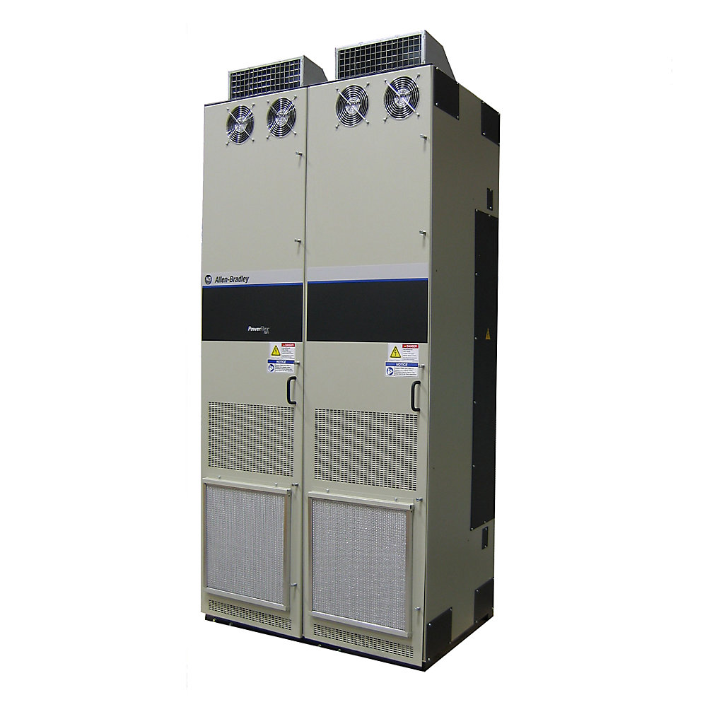
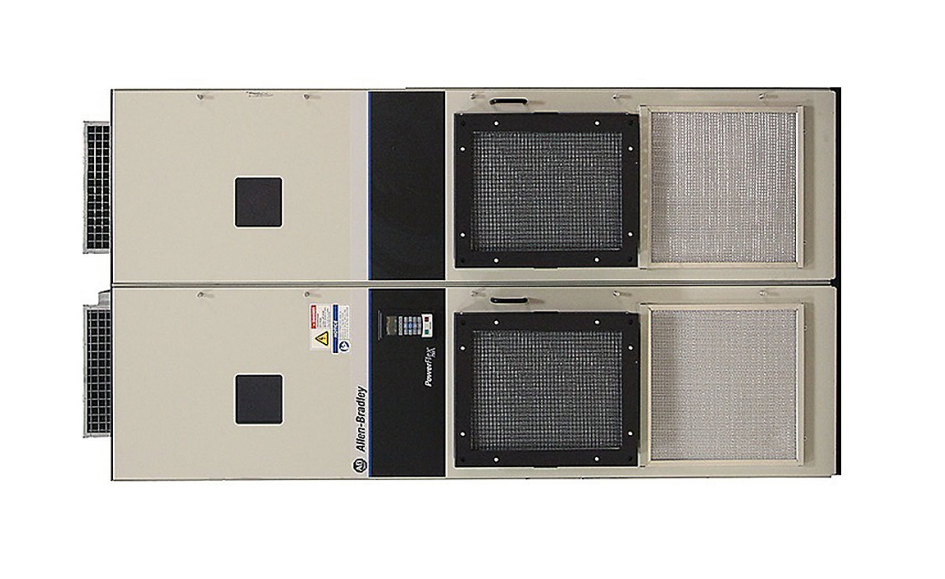
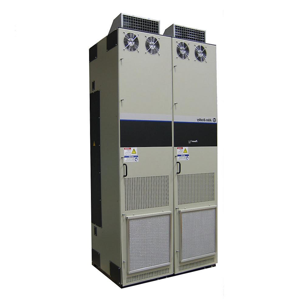
- Allen Bradley
- 20G11NE017AA0NNNNN
- PowerFlex AC Drive
- USA
- 424 × 170 × 212 mm
- 7kg
- Xiamen, China
- New & In Stock
- T/T, PayPal, Western Union
- 1 Year
- 1-3 Working Days
- DHL, UPS, TNT, FedEx and EMS.
- 24-Hour Service
- COO
- 69
Our advantage

Global Logistics
We have a 10-year logistics and express cooperation agreement, so our products can be shipped to any place in the world.

Brand new and original
Our products are imported in bulk from the place of origin. Because of the cooperative relationship, our products are all original and 100% new.

24-hour service
We provide 7*24 hours service to our customers. We will be there whenever you need us.

Price advantage
All our products are priced very favorably because we have our own warehouse and supply.
| Company Information | |||
| [email protected] | |||
| Mobile | +8615980777398 | ||
| +8615980777398 | |||
| 15980777398 |
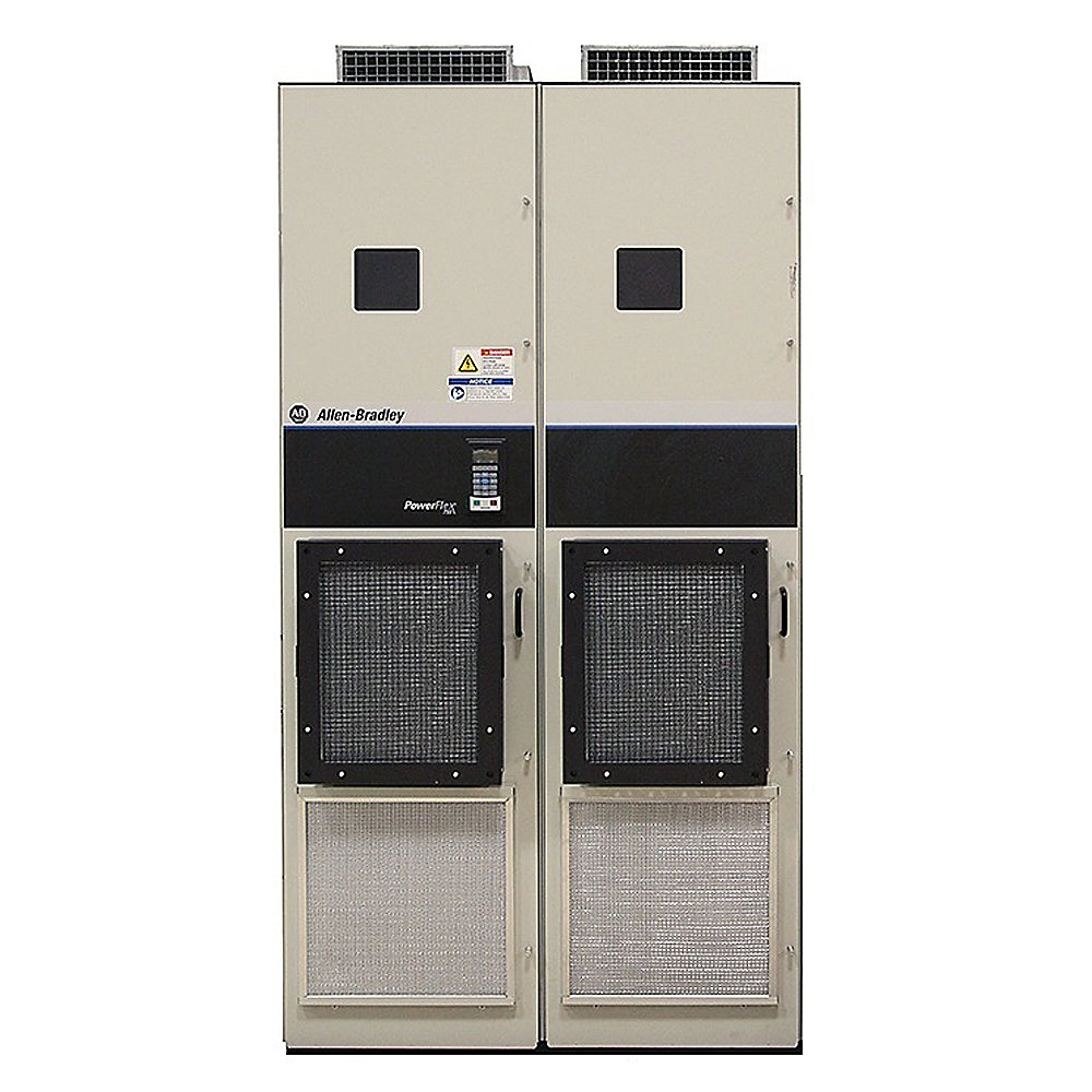
20G11NE017AA0NNNNN — PowerFlex 755 AC Drive
1. Product Overview
The 20G11NE017AA0NNNNN is a PowerFlex 755 series industrial AC variable frequency drive designed for three-phase motor speed and torque control.
This model is a 600 VAC, three-phase, 17 A drive, with a normal-duty rating of approximately 15 HP and a heavy-duty rating of approximately 10 HP.
It is a Frame 3 drive with forced-air cooling, an open-type construction, AC input with DC terminals, embedded EtherNet/IP communication, EMC filtering, a dynamic-braking transistor, and a blank configuration without a local HIM.
The model is intended for industrial motor-control applications where reliable speed regulation, controlled acceleration and deceleration, network communication, diagnostics, and flexible control are required.
Compared with a basic motor starter, a variable frequency drive provides substantially greater control over motor operation. The motor can be started gradually, accelerated to a programmed speed, operated at different speeds, decelerated under controlled conditions, and monitored through an industrial control network.
2. Basic Product Information
| Parameter | Specification |
|---|---|
| Model | 20G11NE017AA0NNNNN |
| Brand | Allen-Bradley |
| Product Family | PowerFlex |
| Product Series | PowerFlex 755 |
| Product Type | Industrial AC Variable Frequency Drive |
| Drive Class | Architecture-level AC drive |
| Voltage Class | 600 VAC |
| Input Phase | 3 Phase |
| Output Phase | 3 Phase |
| Continuous Output Current | 17 A |
| Normal-Duty Rating | 15 HP |
| Heavy-Duty Rating | 10 HP |
| Normal-Duty Power | Approx. 11 kW |
| Heavy-Duty Power | Approx. 7.5 kW |
| Frame Size | Frame 3 |
| Cooling | Forced Air |
| Enclosure | Open Type |
| Input Configuration | AC Input with DC Terminals |
| EMC Filtering | Filtered |
| CM Jumper | Removed |
| Dynamic Braking | DB Transistor |
| Communication | Embedded EtherNet/IP |
| Local HIM | Blank / No HIM |
| Mounting | Panel / Cabinet |
| Approx. Dimensions | 424 × 170 × 212 mm |
| Approx. Weight | Approx. 6.8–7.0 kg |
| Weight (kg) | Approx. 6.8–7.0 kg |
3. Brand and Series
| Category | Information |
|---|---|
| Brand | Allen-Bradley |
| Product Family | PowerFlex |
| Series | PowerFlex 755 |
| Bulletin Family | 20G |
| Product Type | AC Variable Frequency Drive |
| Voltage Group | 600 VAC |
| Current Class | 17 A |
| Frame | Frame 3 |
The 20G11NE017AA0NNNNN belongs to the PowerFlex 755 family.
The PowerFlex 755 series is intended for industrial applications that require more advanced motor control than a simple variable-speed starter.
The series can be used in applications involving conveyors, pumps, fans, blowers, feeders, material-handling machinery, production equipment, process machinery, and other industrial systems.
4. Model Identification
The complete catalog number is:
20G11NE017AA0NNNNN
For practical engineering selection, the most significant characteristics of this configuration are:
- PowerFlex 755 series
- 600 VAC class
- Three-phase operation
- 17 A continuous output rating
- 15 HP normal-duty rating
- 10 HP heavy-duty rating
- Frame 3
- Forced-air cooling
- Open-type construction
- Embedded EtherNet/IP
- AC input with DC terminals
- Filtered EMC configuration
- CM jumper removed
- Dynamic-braking transistor
- Blank / no local HIM
The complete catalog number should be treated as a specific configured drive rather than assuming that another drive with a similar current rating has exactly the same options.
5. Main Electrical Parameters
| Electrical Parameter | 20G11NE017AA0NNNNN |
|---|---|
| Voltage Class | 600 VAC |
| Input Phase | 3 Phase |
| Output Phase | 3 Phase |
| Continuous Output Current | 17 A |
| Normal-Duty Current Reference | 17 A |
| Heavy-Duty Current Reference | 11 A |
| Normal-Duty Rating | 15 HP |
| Heavy-Duty Rating | 10 HP |
| Normal-Duty Power | Approx. 11 kW |
| Heavy-Duty Power | Approx. 7.5 kW |
| Input Frequency | 50/60 Hz class |
| Input Type | AC Input with DC Terminals |
| Output Type | Variable-frequency three-phase AC |
| Cooling | Forced Air |
| Frame | 3 |
| EMC Filtering | Filtered |
| CM Jumper | Removed |
| Dynamic Braking | DB Transistor |
| Communication | Embedded EtherNet/IP |
| HIM | Blank / No HIM |
| Enclosure | Open Type |
6. Output Current
The drive has a 17 A normal-duty continuous output rating.
This rating is important when matching the drive to a motor.
Although horsepower is commonly used when describing a drive, motor nameplate current is normally the more useful value for final selection.
A motor’s current can vary because of:
- Motor efficiency
- Power factor
- Motor voltage
- Motor construction
- Motor speed
- Load characteristics
- Service factor
- Operating temperature
- Application duty
For this reason, a 15 HP motor should not be selected solely because the drive is marked as a 15 HP normal-duty unit. The motor’s actual full-load current should also be checked.
7. Normal-Duty and Heavy-Duty Ratings
The model has two important application ratings.
| Duty | Rating |
|---|---|
| Normal Duty | 15 HP |
| Heavy Duty | 10 HP |
| Normal-Duty Current | 17 A |
| Heavy-Duty Current | 11 A |
Normal-duty applications generally have moderate overload requirements.
Heavy-duty applications may require greater starting torque or more frequent and severe overload operation.
For a high-torque application, the heavy-duty rating should be used as the primary selection reference.
Examples of demanding applications may include:
- Loaded conveyors
- High-inertia machinery
- Mixers
- Material-handling equipment
- Machines with frequent acceleration
- Machines with frequent deceleration
- Equipment requiring high starting torque
8. 600 VAC Class
The 20G11NE017AA0NNNNN is a 600 VAC class drive.
This makes it suitable for industrial electrical systems using a three-phase supply in the 600 VAC class.
It should not be considered a direct substitute for a lower-voltage model simply because the output current is similar.
The following should be checked before substitution:
| Selection Factor | Requirement |
|---|---|
| Supply Voltage | 600 VAC class |
| Supply Phase | Three Phase |
| Drive Current | 17 A ND / 11 A HD |
| Motor Current | Must be within applicable drive rating |
| Motor Voltage | Must be compatible |
| Duty | Normal or Heavy Duty |
| Braking | Check application requirement |
| Cabinet | Suitable enclosure required |
9. Variable Frequency Operation
The main purpose of the drive is to provide controlled variable-frequency power to an AC motor.
Motor speed can be adjusted according to the required process condition.
Instead of running a motor continuously at one fixed speed, the drive can provide a controlled speed profile.
Typical operating stages include:
- Motor enable
- Controlled acceleration
- Normal operating speed
- Speed adjustment
- Controlled deceleration
- Stop
This allows the motor to become an active part of the machine-control strategy.
10. Controlled Acceleration
The drive can gradually increase motor speed.
Controlled acceleration can reduce mechanical shock on:
- Gearboxes
- Couplings
- Shafts
- Bearings
- Belts
- Chains
- Rollers
- Conveyor structures
- Machine frames
This is particularly useful where the motor drives a large mechanical load.
A gradual acceleration profile can also reduce sudden current demand compared with direct-on-line motor starting.
11. Controlled Deceleration
The drive can also control the motor’s deceleration.
Controlled stopping can reduce mechanical shock and improve the behavior of the machine during production.
This can be useful for:
- Conveyors
- Feeders
- Packaging machinery
- Material-handling systems
- Process machinery
- Fans
- Pumps
- High-inertia equipment
The actual stopping time depends on the motor, mechanical load, programmed ramp, DC-bus conditions, and braking arrangement.
12. Dynamic Braking
The 20G11NE017AA0NNNNN includes a dynamic-braking transistor.
Dynamic braking can be useful when the machine needs controlled deceleration and the mechanical load contains significant stored energy.
During deceleration, the motor can return energy to the drive’s DC bus.
A braking resistor can then be used to dissipate the regenerated energy as heat.
This can be useful for:
- High-inertia conveyors
- Material-handling equipment
- Rapid-cycle machinery
- Feed systems
- Production equipment
- Machines requiring shorter controlled stopping times
The braking resistor must be selected according to the actual braking energy and duty cycle.
13. Embedded EtherNet/IP
One of the important features of this configuration is its embedded EtherNet/IP capability.
The drive can be integrated into an industrial automation network.
A typical architecture is:
Controller → EtherNet/IP Network → Drive → Motor
The control system can exchange information such as:
| Data | Typical Function |
|---|---|
| Start Command | Start motor |
| Stop Command | Stop motor |
| Speed Reference | Set motor speed |
| Direction | Set rotation direction |
| Enable | Permit operation |
| Reset | Reset suitable faults |
| Drive Status | Monitor operating condition |
| Output Frequency | Monitor commanded speed |
| Output Current | Monitor motor loading |
| Fault | Identify abnormal operation |
| Alarm | Identify warning conditions |
| Operating State | Monitor drive condition |
This makes the drive suitable for centralized machine control.
14. Blank / No HIM Configuration
This model is configured with a blank / no local HIM.
HIM means Human Interface Module.
A local display is therefore not part of this particular configuration.
This can be useful when the machine already has:
- A central operator panel
- A PLC-based control system
- A networked HMI
- A centralized maintenance interface
Instead of providing a separate local operator display for every drive, the machine can use a centralized interface.
This can simplify the physical appearance of a control cabinet and reduce unnecessary local hardware.
15. Open-Type Construction
The drive uses an open-type enclosure configuration.
It is therefore intended for installation inside an appropriate electrical cabinet or enclosure.
The enclosure should protect the drive against environmental contaminants such as:
- Water
- Oil
- Excessive dust
- Metal particles
- Conductive debris
- Chemical contamination
- Condensation
The cabinet should also provide adequate ventilation and thermal management.
16. Forced-Air Cooling
The drive uses forced-air cooling.
Power semiconductors and other electronic components generate heat during operation.
The cooling system moves air through the drive to remove this heat.
Cabinet designers should consider:
- Ambient temperature
- Drive heat loss
- Cabinet dimensions
- Airflow
- Fan operation
- Filter condition
- Other heat-producing components
- Clearance around the drive
If several drives are installed in one cabinet, the combined heat load should be considered.
17. EMC Configuration
This particular catalog configuration uses a filtered EMC arrangement with the CM jumper removed.
EMC refers to electromagnetic compatibility.
Variable frequency drives use high-speed switching to control motor voltage and frequency. This switching can create electrical noise.
A suitable installation should therefore pay attention to:
- Motor cable selection
- Cable shielding
- Grounding
- Cabinet bonding
- Cable routing
- Separation between power and control wiring
- Communication cable routing
- Motor-frame grounding
The drive’s filter configuration is only one part of the complete EMC installation.
18. Product Introduction
The 20G11NE017AA0NNNNN is a medium-capacity industrial AC drive intended for applications where motor speed and torque need to be actively controlled.
Its 17 A normal-duty capacity makes it suitable for a broad range of medium-size motors.
The drive can regulate motor operation rather than simply providing an on/off function.
A conventional starter generally provides:
Power → Motor ON/OFF
An AC drive can provide:
Power → Adjustable Frequency → Controlled Motor Speed
This difference gives machine designers considerably more flexibility.
19. Typical Applications
| Application | Suitability | Main Reason |
|---|---|---|
| Conveyors | Excellent | Adjustable speed and smooth starting |
| Pumps | Excellent | Variable flow control |
| Fans | Excellent | Variable airflow |
| Blowers | Excellent | Process-air regulation |
| Feeders | Excellent | Adjustable material feed |
| Packaging Equipment | Very Good | Speed coordination |
| Material Handling | Excellent | Controlled acceleration/deceleration |
| Production Machinery | Excellent | Network control |
| Process Machinery | Very Good | Adjustable operating speed |
| Mixers | Good | Variable-speed operation |
| Machine Auxiliaries | Excellent | Centralized automation |
20. Conveyor Applications
Conveyors are one of the most common applications for variable frequency drives.
The drive can provide controlled acceleration and adjustable operating speed.
This is particularly useful when:
- Production speed changes
- Different product sizes are processed
- A conveyor must synchronize with another machine
- Smooth startup is required
- Sudden mechanical shock must be minimized
- Controlled stopping is required
- The conveyor is integrated into a larger automated line
The 17 A capacity also gives the model more current capability than smaller 600 VAC models in the same series.
21. Pump Applications
The drive can regulate pump motor speed according to process requirements.
Possible applications include:
- Water circulation
- Industrial fluid transfer
- Cooling systems
- Process circulation
- Utility pumping
- Fluid-handling systems
A variable-speed pump can operate at different speeds rather than being forced to operate continuously at one fixed speed.
Actual energy savings depend on the pump characteristics, process requirements, motor efficiency, and operating profile.
22. Fan and Blower Applications
Fans and blowers frequently have changing airflow requirements.
A variable-speed drive allows the motor speed to be adjusted.
Typical applications include:
- Factory ventilation
- Exhaust systems
- Cooling equipment
- Process ventilation
- Industrial air systems
- Air-handling machinery
The drive can receive a speed reference from the automation system and provide operating feedback.
23. Feeder Applications
Industrial feeders often require controlled material flow.
Motor speed can influence:
- Feed rate
- Production rate
- Material quantity
- Synchronization with other machinery
The drive is therefore suitable for:
- Material feeders
- Conveyor feeders
- Production feeders
- Packaging feeders
- Processing systems
24. Packaging Equipment
Packaging machinery often requires multiple motors to operate at coordinated speeds.
The drive can be used for:
- Feed conveyors
- Rollers
- Transport systems
- Material handling
- Machine auxiliary sections
- Adjustable-speed mechanisms
EtherNet/IP communication can make it easier to coordinate the drive with the rest of the machine.
25. Material-Handling Equipment
Material-handling machinery can benefit from controlled acceleration, deceleration, and speed regulation.
Typical examples include:
- Transfer conveyors
- Sorting equipment
- Production conveyors
- Feed mechanisms
- Transport machinery
- Automated handling equipment
Dynamic braking can also be useful where a high-inertia load must be slowed down under controlled conditions.
26. Main Product Advantages
26.1 17 A Output Capability
The 17 A rating provides a useful capacity range for medium-size industrial motors.
It gives the model more output capability than the smaller 11 A unit in the same voltage family.
26.2 15 HP Normal-Duty Rating
The approximately 15 HP normal-duty rating makes the drive suitable for many general industrial applications.
26.3 10 HP Heavy-Duty Rating
The 10 HP heavy-duty rating provides a useful reference for applications that require greater overload capability.
26.4 600 VAC Class
The 600 VAC class makes the drive suitable for industrial power systems using the corresponding three-phase voltage class.
26.5 Embedded EtherNet/IP
Embedded EtherNet/IP allows the drive to communicate with a networked automation system without requiring a basic external communication adapter for the core network connection.
26.6 Dynamic-Braking Transistor
The integrated braking transistor is useful for applications where dynamic braking is required.
26.7 Frame 3 Construction
Frame 3 provides a relatively compact mechanical platform for this power range.
This can be useful when cabinet space is limited.
26.8 Forced-Air Cooling
Forced-air cooling provides active thermal management for the power electronics.
26.9 Industrial Diagnostics
The drive can provide operating and fault information useful for commissioning, maintenance, and troubleshooting.
26.10 Flexible Automation Integration
The PowerFlex 755 architecture makes the drive suitable for systems where motor control is closely integrated with machine automation.
27. Mechanical Parameters
The model belongs to Frame 3.
For cabinet planning, the following values can be used as approximate engineering references.
| Mechanical Parameter | Specification |
|---|---|
| Model | 20G11NE017AA0NNNNN |
| Series | PowerFlex 755 |
| Frame | Frame 3 |
| Construction | Open Type |
| Cooling | Forced Air |
| Mounting | Panel / Cabinet |
| Approx. Height | 424 mm |
| Approx. Width | 170 mm |
| Approx. Depth | 212 mm |
| Approx. Dimensions | 424 × 170 × 212 mm |
| Approx. Height | Approx. 16.7 in |
| Approx. Width | Approx. 6.7 in |
| Approx. Depth | Approx. 8.35 in |
| Approx. Product Weight | 6.8–7.0 kg |
| Weight (kg) | Approx. 6.8–7.0 kg |
| Cooling Airflow | Required |
| Mounting Orientation | Vertical |
| Service Clearance | Required |
28. Dimensions and Weight
For engineering planning, the Frame 3 configuration can be considered approximately:
424 mm high × 170 mm wide × 212 mm deep
The approximate bare-drive weight is:
6.8–7.0 kg
The actual shipping package will weigh more.
Shipping weight may include:
- Packaging
- Protective material
- Documentation
- Accessories
- Mounting hardware
Therefore, cabinet structural calculations should use the actual delivered equipment weight when necessary.
| Item | Approximate Value |
|---|---|
| Model | 20G11NE017AA0NNNNN |
| Height | 424 mm |
| Width | 170 mm |
| Depth | 212 mm |
| Dimensions | 424 × 170 × 212 mm |
| Weight | 6.8–7.0 kg |
| Weight (kg) | Approx. 6.8–7.0 kg |
29. Five Same-Series / Related Models
The following five models are useful comparisons within the PowerFlex 755 600 VAC family.
| No. | Model | Voltage | Output Current | Normal-Duty HP | Heavy-Duty HP | Frame | Approx. Dimensions | Weight (kg) |
|---|---|---|---|---|---|---|---|---|
| 1 | 20G11NE011AA0NNNNN | 600 VAC | 11 A | 10 HP | 7.5 HP | 3 | Approx. 424 × 170 × 212 mm | ~6.8 |
| 2 | 20G11NE017AA0NNNNN | 600 VAC | 17 A | 15 HP | 10 HP | 3 | Approx. 424 × 170 × 212 mm | ~6.8–7.0 |
| 3 | 20G11NE022AA0NNNNN | 600 VAC | 22 A | 20 HP | 15 HP | 3 | Frame 3 class | ~7–9 |
| 4 | 20G11NE027AA0NNNNN | 600 VAC | 27 A | 25 HP | 20 HP | 4 | Frame 4 class | ~9–12 |
| 5 | 20G11NE032AA0NNNNN | 600 VAC | 32 A | 30 HP | 25 HP | 4 | Frame 4 class | ~9–12 |
The 20G11NE011AA0NNNNN is a lower-current option, while the 20G11NE022AA0NNNNN, 20G11NE027AA0NNNNN, and 20G11NE032AA0NNNNN provide progressively higher motor capacity.
30. Same-Series Parameter Comparison
| Parameter | 20G11NE011AA0NNNNN | 20G11NE017AA0NNNNN | 20G11NE022AA0NNNNN | 20G11NE027AA0NNNNN | 20G11NE032AA0NNNNN |
|---|---|---|---|---|---|
| Series | PowerFlex 755 | PowerFlex 755 | PowerFlex 755 | PowerFlex 755 | PowerFlex 755 |
| Voltage | 600 VAC | 600 VAC | 600 VAC | 600 VAC | 600 VAC |
| Continuous Current | 11 A | 17 A | 22 A | 27 A | 32 A |
| Normal Duty | 10 HP | 15 HP | 20 HP | 25 HP | 30 HP |
| Heavy Duty | 7.5 HP | 10 HP | 15 HP | 20 HP | 25 HP |
| Frame | 3 | 3 | 3 | 4 | 4 |
| Cooling | Forced Air | Forced Air | Forced Air | Forced Air | Forced Air |
| EtherNet/IP | Embedded | Embedded | Embedded | Embedded | Embedded |
| Dynamic Braking | DB Transistor | DB Transistor | DB Transistor | DB Transistor | DB Transistor |
| Approx. Weight | ~6.8 kg | ~6.8–7.0 kg | ~7–9 kg | ~9–12 kg | ~9–12 kg |
| Dimensions | Frame 3 | 424 × 170 × 212 mm class | Frame 3 | Frame 4 | Frame 4 |
31. Five Same-Brand Popular Alternatives
The following models are useful alternatives from the same brand family, although they are not direct drop-in replacements for the 20G11NE017AA0NNNNN.
| No. | Model | Series | Voltage Class | Current / Capacity | Typical Application | Approx. Dimensions | Weight (kg) |
|---|---|---|---|---|---|---|---|
| 1 | 25B-D2P3N104 | PowerFlex 525 | 480 VAC class | Small-drive range | Small machinery | Compact | ~2–4 |
| 2 | 25B-D010N104 | PowerFlex 525 | 480 VAC class | 10 A class | General machinery | Compact | ~4–6 |
| 3 | 25B-D017N104 | PowerFlex 525 | 480 VAC class | 17 A class | Medium machinery | Compact | ~5–7 |
| 4 | 20F11ND077AA0NNNNN | PowerFlex 753 | 480 VAC class | 77 A class | Larger industrial machinery | Large frame | ~20+ |
| 5 | 20G11ND022JA0NNNNN | PowerFlex 755 | 480 VAC class | 22 A | Industrial motor control | Frame-dependent | ~8–12 |
32. Same-Brand Alternative Comparison
| Parameter | 25B-D2P3N104 | 25B-D010N104 | 25B-D017N104 | 20F11ND077AA0NNNNN | 20G11ND022JA0NNNNN |
|---|---|---|---|---|---|
| Product Family | PowerFlex | PowerFlex | PowerFlex | PowerFlex | PowerFlex |
| Series | PowerFlex 525 | PowerFlex 525 | PowerFlex 525 | PowerFlex 753 | PowerFlex 755 |
| Voltage | 480 VAC class | 480 VAC class | 480 VAC class | 480 VAC class | 480 VAC class |
| Current Class | Small | 10 A class | 17 A class | 77 A class | 22 A |
| Application Level | Compact machinery | General machinery | Medium machinery | Large machinery | Industrial machinery |
| Cooling | Air | Air | Air | Forced Air | Forced Air |
| Network Integration | Available | Available | Available | Advanced | Advanced |
| Dynamic Braking | Configuration dependent | Configuration dependent | Configuration dependent | Available | Available |
| Approx. Weight | ~2–4 kg | ~4–6 kg | ~5–7 kg | ~20+ kg | ~8–12 kg |
| Approx. Dimensions | Compact | Compact | Compact | Large | Larger Frame |
33. Why Choose 20G11NE017AA0NNNNN Instead of the 11 A Model?
The primary difference is output capacity.
| Characteristic | 11 A Model | 17 A Model |
|---|---|---|
| Voltage Class | 600 VAC | 600 VAC |
| Continuous Current | 11 A | 17 A |
| Normal Duty | 10 HP | 15 HP |
| Heavy Duty | 7.5 HP | 10 HP |
| Frame | 3 | 3 |
| Typical Use | Smaller motor | Larger motor / higher load |
The 17 A model is therefore appropriate when the motor requires more current than the 11 A model can provide.
It is also useful when the application requires a higher horsepower rating while remaining within the same general 600 VAC PowerFlex 755 family.
34. Why Choose the 22 A Model?
The 20G11NE022AA0NNNNN is the next major step above the 17 A model in the same 600 VAC family.
It is approximately:
- 22 A continuous
- 20 HP normal duty
- 15 HP heavy duty
This makes it useful where the 17 A rating is insufficient.
However, selecting the larger drive only because it has more current is not always the best solution.
The motor nameplate current, duty cycle, overload requirement, available cabinet space, thermal conditions, and electrical system should all be considered.
35. Advantages for Machine Builders
The 20G11NE017AA0NNNNN is particularly useful for machine builders who need a medium-capacity drive with network integration.
Potential benefits include:
- Adjustable motor speed
- Controlled startup
- Controlled stopping
- Network-based control
- Drive diagnostics
- Dynamic braking
- Medium-size motor capacity
- Cabinet installation
- Industrial automation integration
The blank HIM configuration can also be useful when the machine has a centralized operator interface.
36. Advantages for Automation Engineers
Automation engineers can use the drive as an intelligent motor-control node.
A typical architecture is:
PLC / Controller
↓
EtherNet/IP
↓
20G11NE017AA0NNNNN
↓
Three-Phase Motor
The controller can provide commands while the drive supplies operating feedback.
This allows the drive to be incorporated into machine sequencing and process control.
37. Advantages for Maintenance
Maintenance teams can benefit from the diagnostic information available through the drive.
For example, abnormal current can indicate:
- Mechanical overload
- Conveyor blockage
- Pump problems
- Bearing problems
- Incorrect motor parameters
- Process problems
Drive faults may also indicate:
- Overcurrent
- Overvoltage
- Undervoltage
- Thermal problems
- Communication problems
- Motor-related issues
The available information can help reduce troubleshooting time.
38. Energy-Control Benefits
A variable frequency drive can allow the motor to operate at the speed actually required by the process.
This can be useful in applications where demand changes over time.
For example:
| Process Requirement | Drive Operation |
|---|---|
| Maximum production | Higher speed |
| Normal production | Standard speed |
| Reduced production | Lower speed |
| Setup | Low speed |
| Maintenance | Controlled jog / low-speed operation |
| Stopping | Controlled deceleration |
Actual energy savings vary by application and should not be assumed solely from installing a drive.
39. Installation Considerations
Before installation, verify:
- Incoming voltage
- Phase configuration
- Motor voltage
- Motor full-load current
- Motor horsepower
- Duty requirement
- Braking requirement
- Cabinet dimensions
- Cooling requirements
- Ambient temperature
- Motor cable requirements
- Grounding
- Communication requirements
- Clearance around the drive
- Control architecture
The most important selection point is that the motor’s actual current and duty requirement must remain within the drive’s applicable rating.
40. Mechanical Installation
The approximate mechanical envelope is:
Height: 424 mm
Width: 170 mm
Depth: 212 mm
Weight: approximately 6.8–7.0 kg
These values are useful for preliminary cabinet planning.
The cabinet should provide additional space for:
- Cable routing
- Power terminals
- Control wiring
- Communication wiring
- Ventilation
- Maintenance
- Removal and replacement
A cabinet should not be designed with only the bare dimensions of the drive and zero service clearance.
41. Detailed Technical Specification
| Parameter | 20G11NE017AA0NNNNN |
|---|---|
| Brand | Allen-Bradley |
| Family | PowerFlex |
| Series | PowerFlex 755 |
| Model | 20G11NE017AA0NNNNN |
| Product Type | AC Variable Frequency Drive |
| Voltage Class | 600 VAC, 3 Phase |
| Output Current | 17 A |
| Heavy-Duty Current | 11 A |
| Normal-Duty Rating | 15 HP |
| Heavy-Duty Rating | 10 HP |
| Normal-Duty Power | Approx. 11 kW |
| Heavy-Duty Power | Approx. 7.5 kW |
| Frame Size | Frame 3 |
| Input | AC Input with DC Terminals |
| Output | Variable-frequency three-phase AC |
| Cooling | Forced Air |
| Enclosure | Open Type |
| EMC | Filtered |
| CM Jumper | Removed |
| Dynamic Braking | DB Transistor |
| EtherNet/IP | Embedded |
| HIM | Blank / No HIM |
| Mounting | Panel / Cabinet |
| Approx. Height | 424 mm |
| Approx. Width | 170 mm |
| Approx. Depth | 212 mm |
| Approx. Dimensions | 424 × 170 × 212 mm |
| Weight | Approx. 6.8–7.0 kg |
| Weight (kg) | Approx. 6.8–7.0 kg |
| Typical Applications | Conveyors, pumps, fans, blowers, feeders, packaging, material handling |
| Main Function | Adjustable motor speed and torque control |
42. Product Advantages at a Glance
| Advantage | Practical Benefit |
|---|---|
| 17 A output | Supports medium-size industrial motors |
| 15 HP ND rating | Suitable for general-duty applications |
| 10 HP HD rating | Suitable for more demanding loads within HD rating |
| 600 VAC class | Compatible with higher-voltage industrial systems |
| Embedded EtherNet/IP | Simplifies networked automation |
| Dynamic-braking transistor | Supports controlled braking applications |
| Frame 3 | Relatively compact for its power class |
| Forced-air cooling | Active thermal management |
| EMC filtering | Helps support controlled electromagnetic environment |
| No HIM | Useful for centralized machine interfaces |
| Diagnostics | Helps commissioning and troubleshooting |
| Variable speed | Allows process speed adjustment |
| Controlled acceleration | Reduces mechanical shock |
| Controlled deceleration | Improves stopping behavior |
43. Recommended Application Matching
| Application | Recommended Consideration |
|---|---|
| Conveyor | Very suitable |
| Pump | Very suitable |
| Fan | Very suitable |
| Blower | Very suitable |
| Feeder | Very suitable |
| Packaging machine | Suitable |
| Material handling | Very suitable |
| Mixer | Suitable after torque check |
| High-inertia machine | Suitable with braking evaluation |
| Crusher | Requires careful heavy-duty sizing |
| Hoist | Requires application-specific drive selection |
| High-torque machine | Verify heavy-duty current and overload requirements |
44. Important Selection Note
The five related models listed above should be treated as selection alternatives, not automatic replacement parts.
A replacement drive should be checked against:
- Input voltage
- Motor current
- Motor horsepower
- Duty rating
- Overload requirement
- Braking requirements
- Communication requirements
- Enclosure requirements
- Frame size
- Mechanical dimensions
- Cooling requirements
- Existing control-system configuration
Two drives can have similar horsepower ratings but still require different configurations.
45. Final Product Summary
| Item | Specification |
|---|---|
| Model | 20G11NE017AA0NNNNN |
| Brand | Allen-Bradley |
| Series | PowerFlex 755 |
| Type | Industrial AC Variable Frequency Drive |
| Voltage | 600 VAC class |
| Phase | 3 Phase |
| Continuous Output | 17 A |
| Heavy-Duty Current | 11 A |
| Normal Duty | 15 HP |
| Heavy Duty | 10 HP |
| Normal-Duty Power | Approx. 11 kW |
| Heavy-Duty Power | Approx. 7.5 kW |
| Frame | 3 |
| Cooling | Forced Air |
| Input | AC with DC Terminals |
| EMC | Filtered |
| CM Jumper | Removed |
| Dynamic Braking | DB Transistor |
| Communication | Embedded EtherNet/IP |
| HIM | Blank / No HIM |
| Enclosure | Open Type |
| Approx. Dimensions | 424 × 170 × 212 mm |
| Weight (kg) | Approx. 6.8–7.0 kg |
| Typical Applications | Conveyors, pumps, fans, blowers, feeders, packaging and material handling |
46. Conclusion
The 20G11NE017AA0NNNNN is a 600 VAC, three-phase PowerFlex 755 AC drive with a 17 A normal-duty output rating, approximately 15 HP normal-duty capacity, and approximately 10 HP heavy-duty capacity.
Its Frame 3 construction provides a practical physical size for this power range, while forced-air cooling provides active thermal management.
The embedded EtherNet/IP capability makes the drive well suited to networked industrial automation systems.
The dynamic-braking transistor is another useful feature for machines where controlled deceleration and energy dissipation are important.
The model is particularly appropriate for conveyors, pumps, fans, blowers, feeders, packaging equipment, material-handling machinery, and general industrial production equipment.
For applications requiring higher motor capacity, the 20G11NE022AA0NNNNN, 20G11NE027AA0NNNNN, and 20G11NE032AA0NNNNN provide progressively larger options within the same 600 VAC PowerFlex 755 family.
For smaller motors, the 20G11NE011AA0NNNNN provides a lower-current alternative.
For different voltage requirements or compact machine designs, other PowerFlex models can be considered, but they should not be treated as direct replacements without checking the complete electrical and mechanical requirements.
For preliminary cabinet planning, the 20G11NE017AA0NNNNN can be considered approximately 424 × 170 × 212 mm, with a drive weight in the 6.8–7.0 kg range.
The final selection should always be based on the actual motor nameplate current, application duty, overload requirements, incoming supply, braking requirements, environmental conditions, cabinet design, and required communication architecture.