

ProductPRODUCT
Featured products








Contact Us

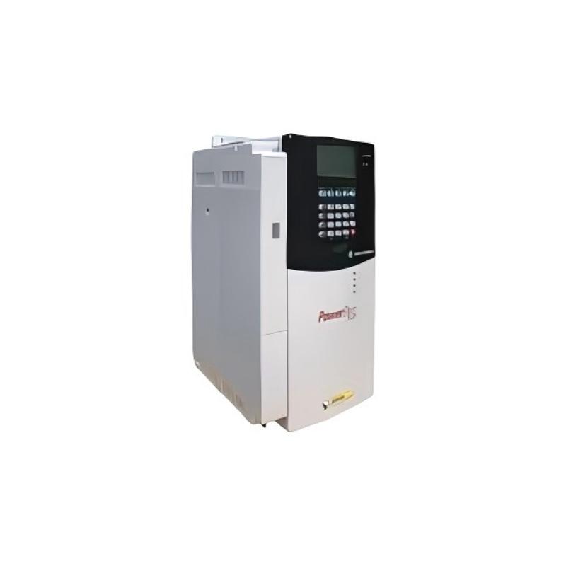
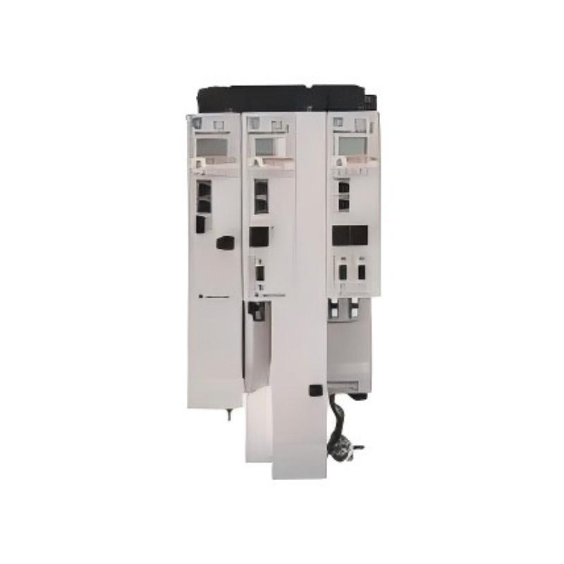
- Allen Bradley
- 20G11JF960JN0NNNNN
- PowerFlex AC Drive
- USA
- 2477 × 1200 × 800 mm
- 1246kg
- Xiamen, China
- New & In Stock
- T/T, PayPal, Western Union
- 1 Year
- 1-3 Working Days
- DHL, UPS, TNT, FedEx and EMS.
- 24-Hour Service
- COO
- 61
Our advantage

Global Logistics
We have a 10-year logistics and express cooperation agreement, so our products can be shipped to any place in the world.

Brand new and original
Our products are imported in bulk from the place of origin. Because of the cooperative relationship, our products are all original and 100% new.

24-hour service
We provide 7*24 hours service to our customers. We will be there whenever you need us.

Price advantage
All our products are priced very favorably because we have our own warehouse and supply.
| Company Information | |||
| [email protected] | |||
| Mobile | +8615980777398 | ||
| +8615980777398 | |||
| 15980777398 |
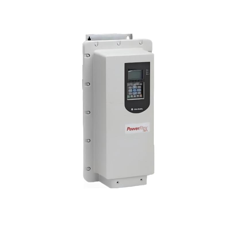
Allen-Bradley 20G11JF960JN0NNNNN PowerFlex 755 AC Drive
1. Product Overview
The 20G11JF960JN0NNNNN is a high-power air-cooled AC drive belonging to the Allen-Bradley PowerFlex 755 series. It is designed for large industrial motors where high current capacity, high motor power, variable-speed control, process control, network communication and industrial enclosure protection are required.
This model is rated for a 690 VAC three-phase power supply and provides a continuous output current of approximately 960 A. Its rated capacity reaches approximately 900 kW under Normal Duty and 800 kW under Heavy Duty.
The drive uses a Frame 9 construction and an IP54 / Type 12, 800 mm deep MCC-style packaged enclosure. It is air cooled and uses forced-air ventilation to remove heat generated by the power electronics.
The standard configuration represented by 20G11JF960JN0NNNNN includes AC input with precharge and DC terminals, filtered EMC configuration, CM jumper installed, no internal dynamic-braking transistor and no HIM keypad.
This is a large industrial drive intended for high-power applications rather than small machine control. Typical applications include large pumps, fans, conveyors, material-handling equipment, industrial ventilation, mining equipment, process machinery and other large rotating loads.
2. Brand and Product Series
| Item | Specification |
|---|---|
| Brand | Allen-Bradley |
| Product Family | PowerFlex |
| Product Series | PowerFlex 755 |
| Product Type | Air-Cooled AC Variable Frequency Drive |
| Model | 20G11JF960JN0NNNNN |
| Application Class | High-Power Industrial Motor Control |
| Input Voltage | 690 VAC |
| Input Phase | 3 Phase |
| Output Current | 960 A |
| Normal Duty Rating | 900 kW |
| Heavy Duty Rating | 800 kW |
| Frame | Frame 9 |
| Enclosure | IP54 / Type 12 |
| Enclosure Construction | 800 mm Deep MCC Style |
| Cooling | Forced Air |
| Dynamic Braking | None |
| Filtering | Filtered |
| CM Jumper | Installed |
| Input Type | AC Input with Precharge and DC Terminals |
| HIM | Blank / No HIM |
| PID | Available |
| Integrated Motion | No |
| Industrial Communication | Embedded EtherNet/IP |
| Typical Application | Pumps, fans, conveyors, process machinery, mining and material handling |
3. Product Identification
The catalog number 20G11JF960JN0NNNNN represents a particular configuration of the PowerFlex 755 platform.
The most important characteristics associated with this model are its high-current 690 VAC architecture, Frame 9 packaged construction, IP54 / Type 12 protection, filtered configuration, CM jumper installed, AC input with precharge and DC terminals, absence of an internal dynamic-braking transistor and absence of a local HIM.
A simplified configuration summary is shown below.
| Catalog Characteristic | Configuration |
|---|---|
| Product family | PowerFlex 755 |
| Drive construction | Packaged / air cooled |
| Voltage class | 690 VAC |
| Current class | 960 A |
| Normal Duty power | 900 kW |
| Heavy Duty power | 800 kW |
| Frame | 9 |
| Enclosure | IP54 / Type 12 |
| Mechanical style | 800 mm deep MCC style |
| Input | AC with precharge and DC terminals |
| Filtering | Installed |
| CM jumper | Installed |
| Dynamic braking | None |
| HIM | None / blank |
| Cooling | Forced air |
| Communication | Embedded EtherNet/IP |
4. Detailed Technical Parameters
| Parameter | Specification |
|---|---|
| Model | 20G11JF960JN0NNNNN |
| Brand | Allen-Bradley |
| Series | PowerFlex 755 |
| Product Type | AC Drive / Variable Frequency Drive |
| Input Voltage | 690 VAC |
| Input Phase | 3 Phase |
| Input Frequency | 50 / 60 Hz class |
| Output Current | 960 A |
| Normal Duty Power | 900 kW |
| Heavy Duty Power | 800 kW |
| Light Duty Power | Approximately 1000 kW class |
| Frame Size | Frame 9 |
| Cooling Method | Forced Air |
| Enclosure Rating | IP54 |
| Enclosure Type | Type 12 |
| Mechanical Style | 800 mm Deep MCC Style |
| AC Input | Yes |
| Precharge | Yes |
| DC Terminals | Yes |
| EMC Filtering | Filtered |
| CM Jumper | Installed |
| Dynamic Braking Transistor | No |
| Embedded EtherNet/IP | Yes |
| PID Control | Yes |
| Integrated Motion | No |
| HIM | No / Blank |
| Safety Function Capability | Yes, with appropriate system configuration |
| Operating Temperature | Approximately -20°C to +60°C class |
| Storage Temperature | Approximately -40°C to +70°C |
| Fan Type | Backward-Curved Centrifugal |
| Approx. Cooling Airflow | 1,805 m³/h |
| Approx. Fan Electrical Input | 0.45 kW |
| Mechanical Depth Class | 800 mm |
| Approx. Cabinet Dimension | Configuration-dependent; approximately 800 mm deep MCC-style construction |
| Approx. Weight | Approximately 1,246 kg for a listed complete packaged configuration |
| Main Applications | Pumps, fans, conveyors, mining, material handling and process equipment |
| Installation Environment | Industrial electrical room / MCC / engineered enclosure |
5. Dimensions and Weight
Because the 20G11JF960JN0NNNNN is a Frame 9 high-power packaged drive, its dimensions and weight are substantially greater than those of ordinary wall-mounted variable-frequency drives.
The catalog configuration identifies an 800 mm deep MCC-style enclosure.
A listed mechanical reference gives a cabinet depth of approximately 78.35 inches, equivalent to approximately 1,990 mm for the relevant overall dimensional direction. The final physical arrangement can vary according to the packaged cabinet configuration, wiring bay, option bay and installation arrangement.
For this reason, dimensional information should be treated as an engineering reference rather than as a substitute for the final mechanical drawing.
The weight is particularly significant. A listed complete packaged configuration is approximately 1,246 kg.
This is a major difference from smaller PowerFlex products. Transportation, lifting, floor loading, cabinet positioning and maintenance access must therefore be planned as part of the installation.
| Mechanical Parameter | Reference Value |
|---|---|
| Frame | 9 |
| Enclosure | IP54 / Type 12 |
| Construction | MCC style |
| Nominal enclosure depth class | 800 mm |
| Listed overall dimensional direction | Approx. 1,990 mm |
| Width | Configuration-dependent |
| Height | Configuration-dependent |
| Approx. Weight | 1,246 kg |
| Cooling | Forced air |
| Maintenance clearance | Must be established from final installation drawing |
| Lifting requirement | Required for large packaged configuration |
For engineering procurement, the 1,246 kg figure should be regarded as a practical reference for a complete packaged configuration, while the final shipping weight should be confirmed against the actual ordered package.
6. Electrical Rating
The 20G11JF960JN0NNNNN is a 690 VAC, three-phase, 960 A high-power drive.
The current rating is one of its most important characteristics.
At 960 A, the drive is designed for motors with very large electrical power requirements.
The Normal Duty rating is approximately 900 kW, while the Heavy Duty rating is approximately 800 kW.
This distinction is important when selecting the drive.
A pump or fan may operate primarily as a variable-torque load and therefore use the Normal Duty rating.
A conveyor, crusher or high-inertia machine may require substantially greater overload capability during acceleration. Such applications should be evaluated against the Heavy Duty rating rather than relying only on the motor’s nominal kW value.
7. Duty Ratings
| Duty | Approximate Power Rating | Typical Application |
|---|---|---|
| Light Duty | 1000 kW class | Lower-overload applications |
| Normal Duty | 900 kW | Pumps, fans and moderate industrial loads |
| Heavy Duty | 800 kW | Conveyors, high-inertia machinery and higher-torque loads |
The 900 kW Normal Duty rating is particularly important for this model.
The 800 kW Heavy Duty rating provides a lower power ceiling when the application requires greater overload capability.
Therefore, an 850 kW motor might be suitable in a Normal Duty application but would not necessarily be appropriate for a Heavy Duty application.
Motor full-load current, overload duration, acceleration time and actual torque requirements should always be checked.
8. Product Introduction
The PowerFlex 755 series is intended for applications that require a combination of motor-speed control, process control, industrial communication and advanced drive functionality.
The 20G11JF960JN0NNNNN is one of the high-power configurations in this family.
It is intended to control large three-phase motors while providing a communication interface for integration with an industrial automation system.
Instead of operating the motor only through a conventional contactor or starter, the drive can continuously regulate motor speed.
This makes it possible to adapt motor output to process demand.
For example, a large pump can operate at a lower speed when the required flow decreases.
A large fan can reduce speed when ventilation requirements are reduced.
A conveyor can accelerate gradually rather than applying full mechanical torque immediately.
This flexibility is the main reason high-power VFDs are used in modern industrial installations.
9. Main Product Features
9.1 960 A High-Current Output
The 960 A output capability makes this drive suitable for very large industrial motors.
It is intended for applications where current requirements are far beyond the range of compact and medium-size drives.
This high current capacity is particularly useful for:
- Large pumps
- Large fans
- Mining conveyors
- Material-handling systems
- Process machinery
- Industrial ventilation
- Large rotating equipment
9.2 900 kW Normal Duty
The approximately 900 kW Normal Duty rating provides a large operating range.
This makes the model appropriate for applications where the load does not continuously require heavy overload capability.
Variable-torque applications are particularly suitable.
9.3 800 kW Heavy Duty
The approximately 800 kW Heavy Duty rating provides additional flexibility for applications that require more demanding motor operation.
Heavy-duty selection should be based on the actual application rather than simply the motor nameplate.
Acceleration torque, inertia, speed range and overload requirements should all be considered.
9.4 690 VAC Three-Phase Input
The 690 VAC class is appropriate for large industrial motor systems.
Higher motor voltage allows large motor power to be transmitted at a more manageable current level than would be required at lower voltage.
This is useful for large industrial power-distribution systems.
9.5 IP54 / Type 12 Enclosure
The IP54 / Type 12 enclosure provides protection appropriate for many industrial environments.
It is designed for use in industrial electrical areas where dust, dirt and incidental moisture may be present.
The rating does not mean that the equipment can be installed without consideration of corrosive gases, conductive dust, direct washdown, salt spray or severe humidity.
Environmental conditions should be evaluated for every installation.
9.6 Forced-Air Cooling
A 900 kW-class drive generates substantial heat.
The drive therefore uses forced-air cooling.
The referenced configuration uses a backward-curved centrifugal fan with approximately 1,805 m³/h airflow.
The cooling system must have sufficient intake and exhaust clearance.
Poor ventilation can increase operating temperature and may result in thermal protection events.
10. Product Applications
10.1 Large Pumping Systems
Large pumping systems are one of the most suitable applications for this drive.
Examples include:
- Water-treatment pumps
- Cooling-water pumps
- Process pumps
- Industrial circulation pumps
- Mining water pumps
- Large utility pumps
- Slurry-related pumping systems
- High-capacity water-transfer systems
The drive can adjust pump speed according to flow or pressure requirements.
This provides more flexible control than operating the pump continuously at a fixed speed.
10.2 Large Fans
Large industrial fans can require hundreds of kilowatts of motor power.
The 20G11JF960JN0NNNNN can provide variable-speed control for such systems.
Typical applications include:
- Mine ventilation
- Furnace exhaust
- Industrial ventilation
- Dust collection
- Process exhaust
- Large air-handling systems
- Combustion-air systems
- Large cooling systems
10.3 Large Conveyors
Conveyors are another important application.
A long conveyor can have substantial mechanical inertia.
The drive can provide a controlled acceleration profile.
This can help reduce mechanical stress on:
- Conveyor belts
- Gearboxes
- Couplings
- Shafts
- Bearings
- Drive pulleys
- Mechanical structures
Controlled acceleration can also make it easier to coordinate multiple conveyor sections.
10.4 Mining Applications
The 960 A rating makes the drive suitable for large mining equipment.
Potential applications include:
- Ore conveyors
- Large fans
- Water pumps
- Material-handling equipment
- Crushing systems
- Processing equipment
- Ventilation systems
Mining installations may require additional environmental and safety considerations, especially where dust, temperature, altitude or hazardous-area requirements are involved.
10.5 Cement and Aggregate Plants
Large cement and aggregate facilities often contain high-power motors.
Potential applications include:
- Conveyors
- Fans
- Pumps
- Crushers
- Material-handling equipment
- Process machinery
The drive’s network communication capability can also make it suitable for centralized plant control.
10.6 Metals Processing
Large metal-processing systems may require substantial motor power.
Variable-speed control can be used for:
- Fans
- Pumps
- Conveyors
- Roll systems
- Material handling
- Auxiliary machinery
The exact motor-control requirements depend on the mechanical process and torque profile.
10.7 Industrial HVAC
Large industrial buildings and facilities can have ventilation and cooling systems requiring very high motor power.
Variable-speed operation allows airflow to be adjusted to actual demand.
This can improve process control and potentially reduce energy consumption compared with constant-speed operation.
11. Product Advantages
11.1 Very High Power Capacity
The main advantage is the combination of 960 A current capacity and 900 kW Normal Duty power.
This allows the drive to control very large industrial motors.
It is appropriate where smaller VFDs cannot provide sufficient output current.
11.2 Variable-Speed Operation
A motor does not always need to operate at maximum speed.
The drive can adjust the motor speed according to process demand.
This is especially useful for pumps and fans.
11.3 Potential Energy Savings
For variable-torque loads, reducing motor speed can significantly reduce power consumption.
This can make a large variable-frequency drive attractive for pumps and fans that spend considerable time below full capacity.
Actual energy savings depend on the load curve, operating hours, motor efficiency and process requirements.
11.4 Controlled Acceleration
Large motors can impose substantial mechanical stress during startup.
Controlled acceleration allows the motor to reach operating speed gradually.
This can reduce mechanical shock and improve equipment life.
11.5 Controlled Deceleration
The drive can also control the motor during stopping.
However, this particular configuration does not include an internal dynamic-braking transistor.
Applications that require frequent rapid deceleration should therefore be evaluated for an appropriate external braking or regenerative solution.
11.6 Industrial Network Integration
Embedded EtherNet/IP allows the drive to communicate with an automation controller.
This makes it possible to exchange:
- Start commands
- Stop commands
- Speed references
- Actual speed
- Output current
- Frequency
- Status
- Warnings
- Fault information
- Process values
11.7 PID Process Control
The drive can be used in closed-loop process applications.
For example, a pump may be required to maintain a pressure setpoint.
The drive can adjust motor speed based on the difference between the desired pressure and the actual pressure.
The same principle can be applied to flow, airflow and other process variables.
11.8 Industrial Protection
The IP54 / Type 12 configuration provides a practical enclosure arrangement for industrial environments.
It reduces the need to place the drive inside a separate basic protective enclosure in applications where the existing industrial environment is suitable for the specified enclosure rating.
12. Automation Architecture
A typical installation can be represented as:
Incoming 690 VAC Supply
↓
Protection and Switching Equipment
↓
PowerFlex 755 Drive
↓
690 VAC Motor
↓
Pump / Fan / Conveyor / Process Equipment
At the automation level:
PLC / Controller
↓
EtherNet/IP
↓
PowerFlex 755
↓
Motor Control
↓
Mechanical Process
The drive therefore serves two roles.
First, it is the power-electronic device that controls the motor.
Second, it is a networked automation component that exchanges operating information with the control system.
13. Communication Functions
The integrated network capability can provide useful information for both operation and maintenance.
| Data | Purpose |
|---|---|
| Start command | Starts motor operation |
| Stop command | Stops motor operation |
| Speed reference | Sets target speed |
| Actual speed | Provides motor speed feedback |
| Output frequency | Indicates drive operating frequency |
| Output current | Indicates motor loading |
| Drive status | Indicates running / stopped / fault state |
| Warning | Identifies abnormal condition |
| Fault | Identifies a trip condition |
| Process reference | Provides process setpoint |
| PID feedback | Provides closed-loop process information |
14. PID Applications
PID control can be particularly valuable for large pumps and fans.
For a pressure-control system, the drive can continuously compare:
Pressure Setpoint
against
Actual Pressure
and then adjust motor speed.
For a ventilation system, a similar method can be used for airflow.
For a water system, the process variable could be flow or pressure.
This eliminates the need to operate the motor at a fixed speed regardless of the actual process requirement.
15. Cooling System
The 20G11JF960JN0NNNNN uses forced-air cooling.
The cooling fan is a backward-curved centrifugal type.
The approximate airflow is:
1,805 m³/h
The approximate electrical input of the cooling fan is:
0.45 kW
These values demonstrate that the cooling system itself is an important part of the installation.
The electrical room or cabinet should provide an appropriate airflow path.
Hot exhaust air should not be allowed to recirculate directly into the drive’s cooling inlet.
16. Environmental Parameters
| Parameter | Typical Specification |
|---|---|
| Operating Temperature | Approximately -20°C to +60°C class |
| Storage Temperature | Approximately -40°C to +70°C |
| Enclosure | IP54 / Type 12 |
| Humidity | Industrial, non-condensing conditions |
| Cooling | Forced Air |
| Installation | Industrial electrical environment |
| Altitude | Application-dependent; derating may apply |
| Dust | Must remain within enclosure/environmental limits |
| Corrosive Atmosphere | Requires separate evaluation |
| Direct Water Exposure | Not recommended without appropriate environmental assessment |
17. Dynamic Braking Considerations
The catalog configuration 20G11JF960JN0NNNNN has no internal dynamic-braking transistor.
This is an important point when selecting the drive.
During deceleration, a motor can return energy to the DC bus.
If the application requires rapid deceleration, this energy must be handled appropriately.
Potential solutions can include:
- External braking equipment
- Regenerative drive systems
- Longer deceleration time
- Mechanical braking
- Application-specific energy-management equipment
The correct solution depends on the inertia, stopping time, motor power and operating cycle.
Applications such as large conveyors, high-inertia rotating machinery and rapid-cycle equipment should therefore receive a dedicated braking analysis.
18. Mechanical Installation
This is a very large packaged drive.
The 800 mm deep MCC-style construction is a major mechanical characteristic.
A listed mechanical dimension is approximately 78.35 inches, or about 1,990 mm, for the relevant cabinet dimension.
The complete installed dimensions can vary according to the exact package configuration.
A practical engineering table is therefore:
| Mechanical Item | Approximate Value |
|---|---|
| Frame | 9 |
| Enclosure | IP54 / Type 12 |
| MCC Style | Yes |
| Nominal enclosure depth class | 800 mm |
| Listed dimensional reference | Approx. 1,990 mm |
| Width | Configuration-dependent |
| Height | Configuration-dependent |
| Weight | Approx. 1,246 kg |
| Cooling | Forced air |
| Installation | Floor-mounted industrial package |
The 1,246 kg weight is especially important.
This is not equipment that should be handled as a normal wall-mounted VFD.
Transportation and installation may require:
- Suitable lifting equipment
- Reinforced floor support
- Adequate access doors
- Transportation route planning
- Cabinet positioning
- Maintenance clearance
- Removal clearance
- Safe power-cable routing
19. Electrical Installation Considerations
Before installation, the following should be evaluated:
| Item | Importance |
|---|---|
| 690 VAC supply | Critical |
| Three-phase supply | Critical |
| Motor rated voltage | Critical |
| Motor full-load current | Critical |
| Normal / Heavy Duty classification | Critical |
| Short-circuit current | Critical |
| Upstream protection | Critical |
| Grounding | Critical |
| Motor cable size | Critical |
| Motor cable length | High |
| EMC requirements | High |
| Cooling airflow | Critical |
| Ambient temperature | High |
| Braking requirements | High |
| Network configuration | High |
| Mechanical clearance | Critical |
| Floor loading | Critical |
| Maintenance access | High |
20. Recommended Same-Series Models
The following five models are useful alternatives or related configurations within the PowerFlex 755 family.
The selection should be based on motor current, voltage, power and duty cycle rather than simply selecting the closest numerical model.
| Model | Voltage | Current | Normal Duty | Heavy Duty | Frame | Enclosure | Dimensions | Weight (kg) |
|---|---|---|---|---|---|---|---|---|
| 20G11JF650JN0NNNNN | 690 VAC | 650 A | 710 kW | 500 kW | 9 | IP54 / Type 12 | 800 mm MCC-style class | Configuration-dependent |
| 20G11JF710JN0NNNNN | 690 VAC | 710 A | 800 kW | 590 kW | 9 | IP54 / Type 12 | 800 mm MCC-style class | Configuration-dependent |
| 20G11JF765JN0NNNNN | 690 VAC | 765 A | 750 kW | 630 kW | 9 | IP54 / Type 12 | 800 mm MCC-style class | Configuration-dependent |
| 20G11JF795JN0NNNNN | 690 VAC | 795 A | 800 kW | 710 kW | 9 | IP54 / Type 12 | 800 mm MCC-style class | Approx. 1,200 kg class* |
| 20G11JF960JN0NNNNN | 690 VAC | 960 A | 900 kW | 800 kW | 9 | IP54 / Type 12 | 800 mm MCC-style class | Approx. 1,246 |
* Actual weight depends on the complete packaged configuration.
21. Same-Series Model Comparison
| Model | Current | Normal Duty | Heavy Duty | Main Advantage |
|---|---|---|---|---|
| 20G11JF650JN0NNNNN | 650 A | 710 kW | 500 kW | Lower-capacity option |
| 20G11JF710JN0NNNNN | 710 A | 800 kW | 590 kW | Suitable for large but lower-current motors |
| 20G11JF765JN0NNNNN | 765 A | 750 kW | 630 kW | Closely related high-power configuration |
| 20G11JF795JN0NNNNN | 795 A | 800 kW | 710 kW | Higher-current alternative |
| 20G11JF960JN0NNNNN | 960 A | 900 kW | 800 kW | Target high-capacity configuration |
The 20G11JF795JN0NNNNN is particularly close to the target model and can be considered where approximately 795 A is sufficient.
The 20G11JF960JN0NNNNN provides a higher current capacity and is appropriate when the motor current or application requirements exceed the lower configurations.
The lower-current models can reduce the amount of unused drive capacity when the motor does not require 960 A.
22. Five Related / Popular Models from the Same Brand
The following models represent popular or useful products from the wider Allen-Bradley variable-frequency-drive range.
They are not direct electrical replacements for the 960 A drive. Instead, they represent different power levels and drive families.
| Model | Series | Input Voltage | Output Current | Normal Duty | Heavy Duty | Frame | Enclosure | Dimensions | Weight (kg) |
|---|---|---|---|---|---|---|---|---|---|
| 25B-D017N114 | PowerFlex 525 | 380–480 VAC | 17.5 A | 7.5 kW | 7.5 kW | C | IP20 | Compact Frame C | Approx. 3–4 |
| 20F11NC043JA0NNNNN | PowerFlex 753 | 400 VAC | 43 A | 22 kW | 18.5 kW | 3 | IP20/IP00 | Frame 3 | Approx. 20 |
| 20GE1ND027JA0NNNNN | PowerFlex 755TS | 480 VAC | 27 A | 20 HP | 15 HP | 3 | IP20/IP00 | Frame 3 | Configuration-dependent |
| 20GE1ND096JA0NNNNN | PowerFlex 755TS | 480 VAC | 96 A | 75 HP | 60 HP | 5 | IP20/IP00 | Frame 5 | Configuration-dependent |
| 20G2AND477JA0NNNNN | PowerFlex 755TS | 480 VAC | 477 A | 400 HP | 300 HP | 7 | IP20/IP00 | Frame 7 | Configuration-dependent |
These models cover a much broader range of applications.
The PowerFlex 525 is intended for smaller machines.
The PowerFlex 753 is suitable for general industrial applications requiring architecture-level drive control.
The PowerFlex 755TS is intended for higher-performance applications and provides a modern control architecture.
The 20G11JF960JN0NNNNN remains the appropriate choice when the application specifically requires a high-power 690 VAC packaged drive in the approximately 900 kW Normal Duty class.
23. PowerFlex 525 — 25B-D017N114
The 25B-D017N114 is a compact PowerFlex 525 drive.
It is dramatically smaller than the 20G11JF960JN0NNNNN and is intended for lower-power machine applications.
Its approximately 17.5 A current capacity makes it suitable for smaller motors.
| Parameter | Specification |
|---|---|
| Model | 25B-D017N114 |
| Series | PowerFlex 525 |
| Input Voltage | 380–480 VAC |
| Input Phase | 3 Phase |
| Output Current | Approx. 17.5 A |
| Normal Duty | Approx. 7.5 kW |
| Heavy Duty | Approx. 7.5 kW |
| Frame | C |
| Enclosure | IP20 |
| Communication | Embedded EtherNet/IP |
| Braking | Internal braking transistor |
| Local Interface | Integrated keypad |
| Cooling | Air cooled |
| Dimensions | Compact Frame C |
| Weight | Approx. 3–4 kg |
| Typical Applications | Small pumps, fans, conveyors and machine tools |
24. PowerFlex 753 — 20F11NC043JA0NNNNN
The 20F11NC043JA0NNNNN is a PowerFlex 753 drive.
It is suitable for industrial machinery requiring more capability than a compact machine-level drive.
| Parameter | Specification |
|---|---|
| Model | 20F11NC043JA0NNNNN |
| Series | PowerFlex 753 |
| Input Voltage | 400 VAC |
| Input Phase | 3 Phase |
| Output Current | 43 A |
| Normal Duty | Approx. 22 kW |
| Heavy Duty | Approx. 18.5 kW |
| Frame | 3 |
| Enclosure | IP20/IP00 |
| Cooling | Forced Air |
| Dynamic Braking | Internal braking transistor |
| DC Terminals | Yes |
| Filtering | Yes |
| CM Jumper | Installed |
| HIM | No door-mounted HIM |
| Dimensions | Frame 3 configuration |
| Weight | Approx. 20 kg |
| Typical Applications | Pumps, fans, conveyors and industrial machinery |
25. PowerFlex 755TS — 20GE1ND027JA0NNNNN
The 20GE1ND027JA0NNNNN is a PowerFlex 755TS model designed for smaller but more demanding high-performance applications.
| Parameter | Specification |
|---|---|
| Model | 20GE1ND027JA0NNNNN |
| Series | PowerFlex 755TS |
| Input Voltage | 480 VAC |
| Input Phase | 3 Phase |
| Output Current | Approx. 27 A |
| Normal Duty | Approx. 20 HP |
| Heavy Duty | Approx. 15 HP |
| Frame | 3 |
| Enclosure | IP20/IP00 |
| Network | Dual EtherNet/IP architecture |
| Braking | Braking transistor |
| Cooling | Air cooled |
| Dimensions | Frame 3, configuration-dependent |
| Weight | Configuration-dependent |
| Typical Applications | Industrial machinery, pumps, fans and conveyors |
26. PowerFlex 755TS — 20GE1ND096JA0NNNNN
The 20GE1ND096JA0NNNNN is a larger PowerFlex 755TS model.
Its approximately 96 A current capacity makes it suitable for medium-power industrial machines.
| Parameter | Specification |
|---|---|
| Model | 20GE1ND096JA0NNNNN |
| Series | PowerFlex 755TS |
| Input Voltage | 480 VAC |
| Input Phase | 3 Phase |
| Output Current | Approx. 96 A |
| Normal Duty | Approx. 75 HP |
| Heavy Duty | Approx. 60 HP |
| Frame | 5 |
| Enclosure | IP20/IP00 |
| Network | Dual EtherNet/IP architecture |
| Braking | Braking transistor |
| Cooling | Air cooled |
| Dimensions | Frame 5, configuration-dependent |
| Weight | Configuration-dependent |
| Typical Applications | Large machine tools, pumps, fans and process equipment |
27. PowerFlex 755TS — 20G2AND477JA0NNNNN
The 20G2AND477JA0NNNNN is a much larger 755TS configuration and provides approximately 477 A output current.
It is suitable for high-power 480 VAC industrial motors, although it remains below the 960 A / 690 VAC target configuration.
| Parameter | Specification |
|---|---|
| Model | 20G2AND477JA0NNNNN |
| Series | PowerFlex 755TS |
| Input Voltage | 480 VAC |
| Input Phase | 3 Phase |
| Output Current | Approx. 477 A |
| Normal Duty | Approx. 400 HP |
| Heavy Duty | Approx. 300 HP |
| Frame | 7 |
| Enclosure | IP20/IP00 |
| Network | Dual EtherNet/IP architecture |
| Braking | Braking transistor |
| Cooling | Forced Air |
| Dimensions | Frame 7, configuration-dependent |
| Weight | Configuration-dependent |
| Typical Applications | Large conveyors, pumps, fans and process machinery |
28. Target Model vs. Related High-Power Models
| Parameter | 20G11JF960JN0NNNNN | 20G11JF795JN0NNNNN | 20G11JF765JN0NNNNN | 20G11JF710JN0NNNNN | 20G11JF650JN0NNNNN |
|---|---|---|---|---|---|
| Series | PowerFlex 755 | PowerFlex 755 | PowerFlex 755 | PowerFlex 755 | PowerFlex 755 |
| Voltage | 690 VAC | 690 VAC | 690 VAC | 690 VAC | 690 VAC |
| Current | 960 A | 795 A | 765 A | 710 A | 650 A |
| Normal Duty | 900 kW | 800 kW | 750 kW | 800 kW | 710 kW |
| Heavy Duty | 800 kW | 710 kW | 630 kW | 590 kW | 500 kW |
| Frame | 9 | 9 | 9 | 9 | 9 |
| Enclosure | IP54 | IP54 | IP54 | IP54 | IP54 |
| Cooling | Forced Air | Forced Air | Forced Air | Forced Air | Forced Air |
| EtherNet/IP | Yes | Yes | Yes | Yes | Yes |
| Dynamic Braking | None | None | None | None | None |
| MCC Style | 800 mm | 800 mm | 800 mm | 800 mm | 800 mm |
| Typical Use | Very large motors | Large motors | Large motors | Large motors | Large motors |
29. Why Choose the 20G11JF960JN0NNNNN?
There are several reasons to choose this model rather than a lower-current PowerFlex 755.
First, the 960 A current rating provides additional electrical capacity.
Second, the 900 kW Normal Duty rating gives it a larger operating range than the 795 A model.
Third, the 800 kW Heavy Duty rating makes it suitable for very large demanding loads.
Fourth, the 690 VAC architecture is appropriate for high-power industrial motor systems.
Fifth, the IP54 / Type 12 packaged enclosure is well suited to many industrial electrical environments.
Finally, the drive can be integrated into an automation system through EtherNet/IP.
30. When the 20G11JF795JN0NNNNN May Be Better
The larger 960 A drive is not always the best choice.
If the motor only requires approximately 700–800 A, selecting a smaller drive may be more economical and may reduce unused capacity.
For example, the 20G11JF795JN0NNNNN may be a more appropriate choice when the motor current is comfortably within the 795 A range and the application does not require the additional capacity of the 960 A model.
The same principle applies to the 765 A, 710 A and 650 A configurations.
Drive sizing should be based on the actual motor current and load profile.
31. Application Selection Table
| Application | Suitability of 20G11JF960JN0NNNNN | Main Reason |
|---|---|---|
| Large centrifugal pump | Excellent | High power and variable-speed control |
| Large industrial fan | Excellent | High power and variable airflow |
| Mine ventilation fan | Excellent | Large motor capacity |
| Long conveyor | Excellent | Controlled acceleration and speed |
| Mining conveyor | Excellent | High current and industrial integration |
| Water-transfer pump | Excellent | High-capacity pumping |
| Cement conveyor | Excellent | Large motor and process control |
| Aggregate plant | Excellent | High-power material handling |
| Crusher | Good | Requires careful Heavy Duty analysis |
| High-inertia machine | Good | Braking requirements must be checked |
| Rapid-cycle machine | Requires evaluation | No internal braking transistor |
| Small pump | Poor | Excessively oversized |
| Small fan | Poor | More economical smaller drive available |
| Low-power machine | Poor | Drive capacity substantially exceeds requirement |
32. Main Advantages at a Glance
| Advantage | Explanation |
|---|---|
| 960 A output | Suitable for very large industrial motors |
| 900 kW Normal Duty | High-capacity variable-speed operation |
| 800 kW Heavy Duty | Suitable for demanding applications |
| 690 VAC | Appropriate for high-power motor systems |
| IP54 / Type 12 | Industrial enclosure protection |
| Frame 9 | High-power packaged construction |
| Forced-air cooling | Supports high-power operation |
| EtherNet/IP | Integration with industrial automation |
| PID control | Closed-loop process control |
| Variable speed | Better process flexibility |
| Controlled acceleration | Reduced mechanical starting shock |
| Diagnostic information | Easier operation and maintenance |
| Filtered configuration | Improved electrical compatibility |
| Precharge | Supports controlled DC-bus charging |
| DC terminals | Supports appropriate DC-bus configurations |
33. Important Limitations
The high capacity of the 20G11JF960JN0NNNNN also creates several practical considerations.
The physical size is large.
The approximate 1,246 kg weight means that normal manual handling is impossible.
The 690 VAC supply requires appropriate high-voltage electrical engineering.
The forced-air cooling system requires sufficient ventilation.
The absence of an internal dynamic-braking transistor means that high-inertia applications requiring rapid stopping require additional analysis.
The lack of a local HIM means that the local operator interface must be considered separately if required.
The drive is therefore best suited to a properly engineered industrial installation rather than a simple machine-panel retrofit.
34. Maintenance Considerations
A high-power drive requires regular attention to thermal and electrical conditions.
Important maintenance points include:
- Cooling fans
- Air passages
- Electrical terminals
- Grounding connections
- Power connections
- Control wiring
- Network connections
- Environmental contamination
- Fault history
- Warning history
- Operating temperature
- Motor cable condition
- Cabinet ventilation
The cooling fans are particularly important.
Fan degradation can reduce airflow and increase internal temperature.
Dust accumulation can also reduce cooling performance.
Regular inspection can help identify cooling and electrical problems before they become serious equipment failures.
35. Recommended Maintenance Focus
| Maintenance Area | Main Check |
|---|---|
| Cooling fan | Noise, vibration and airflow |
| Ventilation | Air inlet and exhaust unobstructed |
| Power terminals | Loose connections and abnormal heating |
| Grounding | Proper electrical continuity |
| Control wiring | Secure and undamaged |
| Network | Stable communication |
| Fault history | Repeated trips or abnormal conditions |
| Environmental condition | Dust, moisture and contamination |
| Motor cable | Insulation and connection condition |
| Cabinet | Cleanliness and airflow |
| Mechanical mounting | Secure installation |
| Temperature | No abnormal thermal condition |
36. Engineering Selection Checklist
| Selection Item | Requirement |
|---|---|
| Motor voltage | Compatible with 690 VAC system |
| Motor current | Within 960 A drive capability |
| Motor power | Within appropriate duty rating |
| Normal Duty | Up to approximately 900 kW |
| Heavy Duty | Up to approximately 800 kW |
| Load type | Determine variable torque / constant torque / high inertia |
| Acceleration | Check required acceleration time |
| Deceleration | Check required stopping time |
| Braking | External solution may be required |
| Enclosure | IP54 / Type 12 |
| Cooling | Adequate forced-air ventilation |
| Communication | EtherNet/IP integration if required |
| Dimensions | Confirm final mechanical drawing |
| Weight | Approximately 1,246 kg reference |
| Floor loading | Must be evaluated |
| Lifting | Appropriate lifting equipment required |
| Cable routing | Must allow adequate installation space |
| Maintenance access | Must be provided |
| Environment | Temperature, humidity and dust must be checked |
37. Product Positioning
Within the PowerFlex 755 family, the 20G11JF960JN0NNNNN sits at the high-power end of the 690 VAC range.
It is considerably larger and more powerful than drives used in ordinary factory machinery.
Its primary role is controlling very large industrial motors.
A simplified product hierarchy can be understood as:
Small Machine Drives
→ Compact motor control
Medium Industrial Drives
→ General industrial motor control
PowerFlex 755 / 755TS
→ Advanced industrial motor and process control
20G11JF960JN0NNNNN
→ High-power 690 VAC packaged motor control
This makes the model particularly relevant to large process plants, mining facilities, water systems, material-handling systems and heavy industrial production environments.
38. Recommended Model Selection by Motor Power
| Approximate Motor Power | Suggested Drive Range | Typical Application |
|---|---|---|
| Below 10 kW | PowerFlex 525 class | Small machines |
| 10–50 kW | PowerFlex 753 / 755 class | General industrial machines |
| 50–200 kW | PowerFlex 753 / 755 / 755TS | Pumps, fans, conveyors |
| 200–400 kW | PowerFlex 755 / 755TS | Large industrial machinery |
| 400–700 kW | PowerFlex 755 high-power configurations | Large pumps, fans and conveyors |
| 700–800 kW | 795–960 A PowerFlex 755 configurations | Very large industrial loads |
| 800–900 kW | 20G11JF960JN0NNNNN Normal Duty class | Very large pumps, fans and process equipment |
| Above 900 kW | Larger PowerFlex configurations | Extra-high-power industrial applications |
39. Final Technical Summary
| Category | Specification |
|---|---|
| Model | 20G11JF960JN0NNNNN |
| Brand | Allen-Bradley |
| Series | PowerFlex 755 |
| Product Type | Air-Cooled AC Drive |
| Voltage | 690 VAC |
| Phase | 3 Phase |
| Output Current | 960 A |
| Normal Duty | 900 kW |
| Heavy Duty | 800 kW |
| Light Duty | Approximately 1000 kW class |
| Frame | 9 |
| Enclosure | IP54 / Type 12 |
| Construction | 800 mm Deep MCC Style |
| Cooling | Forced Air |
| Input | AC with Precharge |
| DC Terminals | Yes |
| Filtering | Filtered |
| CM Jumper | Installed |
| Dynamic Braking | None |
| HIM | None / Blank |
| EtherNet/IP | Embedded |
| PID | Yes |
| Integrated Motion | No |
| Fan Type | Backward-Curved Centrifugal |
| Cooling Airflow | Approximately 1,805 m³/h |
| Fan Input Power | Approximately 0.45 kW |
| Operating Temperature | Approximately -20°C to +60°C class |
| Storage Temperature | Approximately -40°C to +70°C |
| Mechanical Depth Class | 800 mm |
| Listed Dimensional Reference | Approximately 1,990 mm relevant cabinet dimension |
| Weight | Approximately 1,246 kg |
| Main Applications | Pumps, fans, conveyors, mining, material handling, process machinery |
| Main Advantage | High-power variable-speed motor control |
| Main Selection Concern | Duty, braking, cooling, mechanical installation and motor current |
40. Conclusion
The 20G11JF960JN0NNNNN is a high-capacity Allen-Bradley PowerFlex 755 AC drive designed for large industrial motor applications.
Its key electrical characteristics are 690 VAC, three-phase input, 960 A output current, 900 kW Normal Duty and 800 kW Heavy Duty.
The drive is built in a Frame 9, IP54 / Type 12, 800 mm deep MCC-style package and uses forced-air cooling.
The combination of high current capacity, high power rating, industrial enclosure protection, process-control functions and EtherNet/IP communication makes it particularly suitable for large pumps, fans, conveyors, mining systems, material-handling equipment and large process machinery.
For pumping and fan applications, variable-speed operation can provide more precise process control and may reduce energy consumption when the process does not require maximum motor output.
For conveyor applications, controlled acceleration can reduce mechanical shock and improve the starting behavior of high-inertia equipment.
For automated production systems, the embedded EtherNet/IP capability allows the drive to exchange commands, operating values, warnings and fault information with the control system.
The main points requiring special attention are the 960 A current rating, 900 kW Normal Duty rating, 800 kW Heavy Duty rating, approximately 1,246 kg reference weight, large Frame 9 mechanical construction, cooling requirements and lack of an internal dynamic-braking transistor.
Compared with the 20G11JF795JN0NNNNN, this model provides a higher 960 A current rating and a higher 900 kW Normal Duty capacity.
Compared with the 20G11JF765JN0NNNNN, it provides substantially greater current and power capability.
The 20G11JF650JN0NNNNN, 20G11JF710JN0NNNNN, 20G11JF765JN0NNNNN and 20G11JF795JN0NNNNN are useful lower-capacity related configurations within the same PowerFlex 755 family.
For smaller industrial equipment, models such as the 25B-D017N114, 20F11NC043JA0NNNNN, 20GE1ND027JA0NNNNN and 20GE1ND096JA0NNNNN provide more appropriately sized solutions.
For a high-power 690 VAC installation, however, the 20G11JF960JN0NNNNN is best understood as a 900 kW-class industrial motor-control system rather than simply a conventional VFD.
The correct selection should always begin with the motor’s voltage and full-load current, followed by the load profile, duty classification, acceleration and deceleration requirements, braking requirements, environmental conditions, cooling, communication requirements and mechanical installation.
In practical terms, the model can be summarized as:
960 A + 690 VAC + 900 kW Normal Duty + 800 kW Heavy Duty + Frame 9 + IP54 / Type 12 + Forced Air + EtherNet/IP + High-Power Industrial Motor Control.