

ProductPRODUCT
Featured products








Contact Us
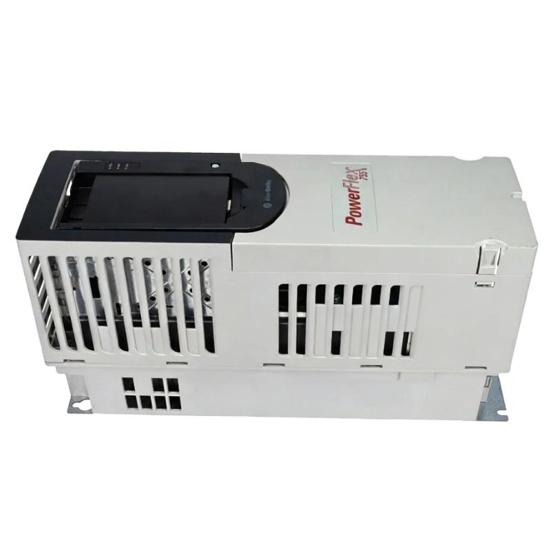
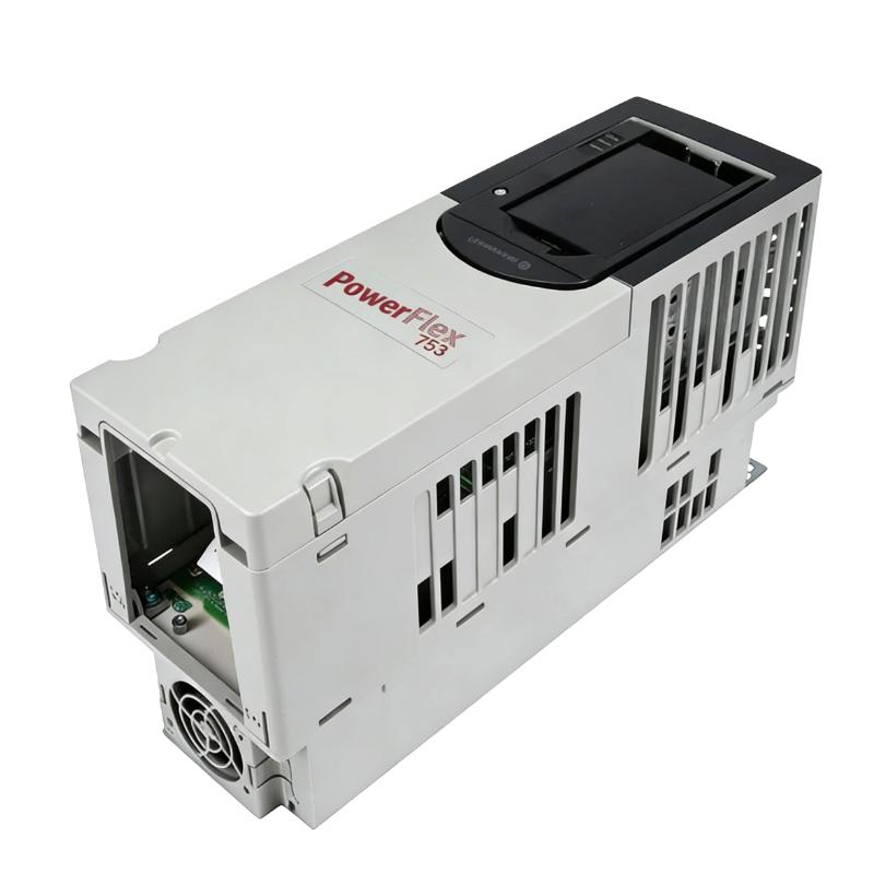
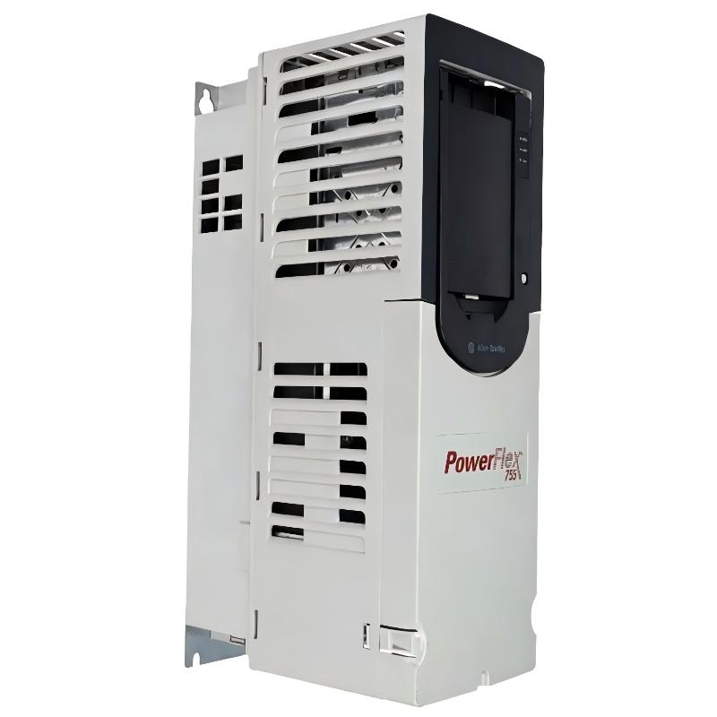
- Allen Bradley
- 20G11BF590JN0NNNNN
- PowerFlex AC Drive
- USA
- 2,453 mm × 1,200 mm × 600 mm
- 1246kg
- Xiamen, China
- New & In Stock
- T/T, PayPal, Western Union
- 1 Year
- 1-3 Working Days
- DHL, UPS, TNT, FedEx and EMS.
- 24-Hour Service
- COO
- 44
Our advantage

Global Logistics
We have a 10-year logistics and express cooperation agreement, so our products can be shipped to any place in the world.

Brand new and original
Our products are imported in bulk from the place of origin. Because of the cooperative relationship, our products are all original and 100% new.

24-hour service
We provide 7*24 hours service to our customers. We will be there whenever you need us.

Price advantage
All our products are priced very favorably because we have our own warehouse and supply.
| Company Information | |||
| [email protected] | |||
| Mobile | +8615980777398 | ||
| +8615980777398 | |||
| 15980777398 |
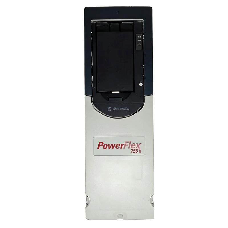
20G11BF590AN0NNNNN PowerFlex 755 AC Drive — Detailed Product Information, Technical Parameters, Applications, Advantages and Related Models
1. Product Overview
The 20G11BF590AN0NNNNN is a high-power industrial AC variable frequency drive from the Allen-Bradley PowerFlex 755 series. It is designed for demanding three-phase motor-control applications where conventional compact frequency converters are not sufficient.
This model is configured for a 690 VAC, three-phase power system and provides a continuous output current rating of approximately 590 A. Its published power ratings are approximately 630 kW for Light Duty, 560 kW for Normal Duty and 450 kW for Heavy Duty.
The drive uses an air-cooled design, a Frame 9 power architecture and a Type 1 / IP20, 600 mm deep MCC-style construction. It is intended for installation in a suitable industrial electrical environment, particularly applications where a large motor drive is installed as part of a centralized motor-control or electrical distribution system.
The model includes embedded EtherNet/IP communication, allowing it to be integrated into an industrial automation network. This allows operating commands, speed references, status information, fault information and selected drive data to be exchanged with the plant control system.
The model is also configured with an EMC filter, while the common-mode capacitor arrangement is associated with the catalog-number configuration. It does not include an internal dynamic-braking resistor or internal dynamic-braking transistor.
The 20G11BF590AN0NNNNN is therefore best understood as a large industrial variable-speed drive intended for motors in the several-hundred-kilowatt range rather than for small machine motors.
The product is particularly appropriate for applications involving large pumps, fans, conveyors, compressors, process machinery, material-handling equipment, mining machinery and other industrial loads requiring controlled motor speed.
2. Basic Product Information
| Item | Specification |
|---|---|
| Product Model | 20G11BF590AN0NNNNN |
| Brand | Allen-Bradley |
| Product Family | PowerFlex |
| Product Series | PowerFlex 755 |
| Product Type | Air-Cooled AC Variable Frequency Drive |
| Drive Class | High-Power Industrial AC Drive |
| Input Voltage | 690 VAC |
| Input Phase | 3 Phase |
| Input Frequency | 50/60 Hz system dependent |
| Rated Output Current | 590 A |
| Light Duty Rating | Approximately 630 kW |
| Normal Duty Rating | Approximately 560 kW |
| Heavy Duty Rating | Approximately 450 kW |
| Frame Size | Frame 9 |
| Cooling | Air Cooled / Forced Air |
| Enclosure | IP20 / Type 1 |
| Mechanical Construction | 600 mm Deep MCC Style |
| Approx. Height | 2,453 mm |
| Approx. Width | 1,200 mm |
| Approx. Depth | 600 mm |
| Approx. Weight (kg) | Approximately 1,246 kg |
| Input Configuration | AC Input with Precharge and DC Terminals |
| Communication | Embedded EtherNet/IP |
| Filtering | EMC Filter |
| Common-Mode Configuration | Jumper Removed |
| Dynamic Braking | None |
| HIM | Blank / No HIM |
| Motor Type | Three-Phase AC Motor |
| Installation | Industrial Electrical Cabinet / MCC |
| Application Level | Medium-to-High Power Industrial Motor Control |
| Typical Motor Range | Several hundred kW |
| Product Architecture | PowerFlex 755 |
| Primary Function | Variable-Speed AC Motor Control |
3. Detailed Technical Parameters
| Parameter | Technical Specification |
|---|---|
| Catalog Number | 20G11BF590AN0NNNNN |
| Brand | Allen-Bradley |
| Series | PowerFlex 755 |
| Drive Type | AC Variable Frequency Drive |
| Input Voltage | 690 VAC |
| Input Phase | Three Phase |
| Input Frequency | 50/60 Hz, application dependent |
| Output Current | 590 A |
| Light Duty Output Rating | 630 kW |
| Normal Duty Output Rating | 560 kW |
| Heavy Duty Output Rating | 450 kW |
| Frame | Frame 9 |
| Cooling | Forced Air |
| Enclosure Type | Type 1 |
| IP Rating | IP20 |
| Cabinet Style | MCC Style |
| Cabinet Depth | 600 mm |
| Approx. Height | 2,453 mm |
| Approx. Width | 1,200 mm |
| Approx. Depth | 600 mm |
| Approx. Weight (kg) | 1,246 kg |
| Input Arrangement | AC Input with Precharge and DC Terminals |
| DC Bus Terminals | Included |
| Network Interface | Embedded EtherNet/IP |
| EMC Filter | Included |
| CM Jumper | Removed |
| Dynamic Braking Resistor | None |
| Dynamic Braking Transistor | None |
| HIM | Blank / No HIM |
| Mounting | MCC / Cabinet Installation |
| Motor Control | Variable-Speed AC Motor Control |
| Intended Load | Large Industrial Motor |
| Duty Modes | Light Duty / Normal Duty / Heavy Duty |
| Typical Applications | Pumps, fans, conveyors, compressors, process equipment |
| Installation Environment | Protected industrial electrical environment |
| Drive Architecture | High-Power PowerFlex 755 |
| Main Control Purpose | Speed and torque control |
| Automation Integration | Industrial Ethernet communication |
| Service Requirement | Industrial maintenance and ventilation required |
The physical dimensions and weight should be regarded as approximate equipment-selection values. Final cabinet drawings, shipping dimensions and lifting weight should be checked against the exact equipment configuration before transportation or installation planning.
4. Product Model Number Explanation
The catalog number 20G11BF590AN0NNNNN contains information describing the basic configuration of the drive.
The 20G prefix identifies the PowerFlex 755 family.
The B enclosure designation is associated with the IP20 / Type 1, 600 mm deep MCC-style configuration.
The F identifies the 690 VAC voltage class.
The 590 portion corresponds to the approximately 590 A current class.
The A configuration identifies the filtering and common-mode capacitor arrangement used by this catalog number. In this configuration, the EMC filtering is provided while the common-mode jumper is removed.
The N dynamic-braking designation means that this configuration does not include an internal dynamic-braking resistor or internal dynamic-braking transistor.
The remaining N-coded positions indicate that the corresponding optional features are not selected in those catalog positions.
For engineering selection, it is important to treat the catalog number as a complete configuration. Changing only one character can change the enclosure, filtering, braking, voltage, current or other characteristics.
5. Product Series
The 20G11BF590AN0NNNNN belongs to the:
| Classification | Product |
|---|---|
| Brand | Allen-Bradley |
| Product Category | Industrial AC Drives |
| Product Family | PowerFlex |
| Series | PowerFlex 755 |
| Model Class | High-Power AC Drive |
| Frame | Frame 9 |
| Voltage Class | 690 VAC |
| Current Class | 590 A |
| Installation Style | MCC Style |
| Cooling | Air Cooled |
| Network | Embedded EtherNet/IP |
The PowerFlex 755 series is intended for industrial applications where motor control, process coordination, diagnostics and automation-network integration are important.
Compared with compact drives designed for simple machine applications, the PowerFlex 755 architecture is better suited to larger motors and more sophisticated industrial systems.
6. Product Introduction
The 20G11BF590AN0NNNNN is designed to control large three-phase AC motors by continuously adjusting the electrical output supplied to the motor.
Instead of allowing the motor to operate only at a fixed line frequency, the drive provides controlled frequency and voltage.
This allows motor speed to be adjusted according to the requirements of the production process.
For industrial equipment such as pumps and fans, this can be particularly useful because the process demand may change throughout the operating cycle.
For conveyors and material-handling machinery, variable-speed control can provide smoother starting and stopping.
For large process machines, the drive can provide coordinated speed control while communicating operating information to a central automation system.
The combination of 690 VAC input, 590 A output current and up to approximately 630 kW Light Duty power makes this model suitable for substantial industrial machinery.
7. Electrical Performance
The most important electrical parameter is the 590 A output current rating.
This current capacity allows the drive to control a large three-phase AC motor.
The drive has three primary duty classifications:
| Duty Classification | Approx. Power Rating | Typical Application |
|---|---|---|
| Light Duty | 630 kW | Variable-torque or moderate-overload applications |
| Normal Duty | 560 kW | General industrial process applications |
| Heavy Duty | 450 kW | High-torque or demanding overload applications |
| Output Current | 590 A | Maximum continuous current class |
The difference between the three power ratings is important.
A motor should not be selected only according to the largest Light Duty rating.
If the application requires high starting torque, frequent acceleration, repeated overload or continuous operation under demanding mechanical conditions, the Heavy Duty rating may be the more appropriate reference.
For example, a machine with a nominal motor power close to 500 kW could potentially be suitable under one duty classification while exceeding the appropriate rating under another.
Motor current and application duty should therefore be evaluated together.
8. Dimensions and Weight
The 20G11BF590AN0NNNNN is a Frame 9 MCC-style industrial drive rather than a compact wall-mounted inverter.
Its approximate physical dimensions are:
Height: 2,453 mm
Width: 1,200 mm
Depth: 600 mm
The approximate equipment weight is:
1,246 kg
| Mechanical Parameter | Specification |
|---|---|
| Frame | Frame 9 |
| Height | Approx. 2,453 mm |
| Width | Approx. 1,200 mm |
| Depth | Approx. 600 mm |
| Cabinet Depth | 600 mm |
| Enclosure | IP20 / Type 1 |
| Construction | MCC Style |
| Cooling | Forced Air |
| Approx. Weight (kg) | 1,246 kg |
| Installation Type | Cabinet / MCC |
| Equipment Class | Large industrial electrical equipment |
The weight is significant enough that transportation and installation should be planned as a dedicated engineering activity.
Suitable lifting equipment may be required.
The installation location should also be evaluated for floor loading, access width, cabinet service clearance and cable-entry requirements.
The stated dimensions should not be used as a replacement for the final mechanical drawing when designing the foundation or electrical-room layout.
9. Cooling System
The drive uses an air-cooled / forced-air cooling system.
A drive in the 590 A class produces considerable heat during operation.
Therefore, the electrical room or cabinet installation must provide adequate ventilation.
The cooling system should have sufficient airflow and should not be obstructed by nearby equipment.
Dust accumulation can also affect the performance of cooling components over time.
For industrial installations, regular inspection of fans, air paths and cabinet cleanliness is important.
A suitable room temperature and ventilation arrangement should be maintained according to the installation requirements.
10. Product Applications
10.1 Large Pump Systems
Large pumps are one of the most suitable applications for this drive.
A pump does not necessarily need to operate at full speed throughout the entire production cycle.
Variable-speed control allows the motor speed to follow the required flow or pressure.
Typical applications include:
- Industrial water circulation
- Cooling-water systems
- Process-water systems
- Water treatment
- Large pumping stations
- Industrial fluid transfer
- Cooling systems
- Process plants
For centrifugal pump applications, reducing speed can also provide significant energy benefits when the process permits lower flow operation.
10.2 Large Fans and Blowers
Large industrial fans can require hundreds of kilowatts of motor power.
The drive can adjust fan speed according to airflow demand.
Potential applications include:
- Industrial ventilation
- Process exhaust
- Combustion air
- Cooling systems
- Dust extraction
- Furnace ventilation
- Large building ventilation
- Industrial air-handling systems
Variable-speed control can provide more precise process control than fixed-speed operation.
10.3 Mining Conveyors
Mining conveyors often operate with large motors and substantial mechanical inertia.
Controlled acceleration can help reduce sudden mechanical stress.
The drive can provide controlled motor speed while communicating with the larger automation system.
Potential benefits include smoother starting, controlled stopping and better coordination with upstream and downstream material-handling equipment.
10.4 Cement and Mineral Processing
Cement plants use many large motors.
Potential applications include:
- Process fans
- Large conveyors
- Mills
- Crushers
- Pumps
- Material-handling equipment
- Exhaust systems
The drive’s 690 VAC input and 590 A current capacity make it appropriate for substantial motor systems in this field.
10.5 Steel and Metals Processing
Large metal-processing systems may use high-power motors for rollers, fans, pumps and material-handling machinery.
Variable-speed control can be used to coordinate motor operation with production requirements.
10.6 Large Material-Handling Systems
Large conveyors, feeders and material-handling equipment can benefit from controlled acceleration and deceleration.
This can reduce mechanical shock and provide better control over material flow.
10.7 Large Compressor Applications
Some compressor systems can use variable-speed motor control.
However, compressor selection must consider compressor type, torque requirements, operating speed range, acceleration requirements and process control.
The drive should therefore be selected based on the complete compressor duty rather than only the motor horsepower.
11. Product Advantages
11.1 High Power Capacity
The first major advantage is the high power capacity.
The drive provides approximately:
630 kW Light Duty
560 kW Normal Duty
450 kW Heavy Duty
This places the product in a substantially higher power category than compact general-purpose drives.
11.2 690 VAC Input
The 690 VAC voltage class is well suited to large industrial motors.
At high power levels, higher motor-system voltage can reduce current compared with an equivalent lower-voltage power system.
This can be beneficial for large industrial electrical distribution systems.
11.3 590 A Current Rating
The 590 A current rating provides enough capacity for large industrial motors.
This makes the drive suitable for substantial process machinery rather than small standalone equipment.
11.4 Embedded EtherNet/IP
Embedded EtherNet/IP is one of the major advantages for industrial automation.
The drive can communicate with a compatible controller and provide useful information such as:
- Speed reference
- Actual speed
- Drive status
- Motor current
- Warning status
- Fault status
- Diagnostic information
- Operating commands
- Parameter information
This reduces the need to treat the drive as an isolated motor-control device.
11.5 Controlled Motor Starting
Large motors can draw significant current and produce substantial mechanical torque during startup.
A variable frequency drive can control the acceleration process.
This can help reduce mechanical shock and provide smoother machine startup.
11.6 Variable-Speed Operation
The motor can operate at different speeds according to process requirements.
This is particularly valuable for pumps, fans and conveyors.
Instead of maintaining maximum speed continuously, the drive can respond to changing production requirements.
11.7 Industrial-Scale Construction
The Frame 9 MCC-style configuration is designed for large industrial electrical installations.
This makes it more appropriate for centralized motor-control rooms and large industrial electrical systems than compact machine-mounted drives.
11.8 Integrated Diagnostics
The networked drive can provide status and fault information to the control system.
This can make troubleshooting easier and reduce the amount of time required to identify operating problems.
12. Filtering and EMC Characteristics
The specified 20G11BF590AN0NNNNN configuration includes an EMC filter.
The catalog configuration also specifies the common-mode capacitor jumper as removed.
This arrangement is relevant to the electrical installation because filtering and common-mode configuration can influence electromagnetic compatibility and grounding behavior.
The appropriate configuration should always be selected according to the motor, cable system, grounding arrangement and installation environment.
The filter configuration should not be changed casually after installation.
13. Dynamic Braking
This model does not include an internal dynamic-braking resistor or internal dynamic-braking transistor.
This is important when selecting the drive for high-inertia machinery.
Some applications require rapid deceleration.
When the motor decelerates, energy can flow back toward the drive’s DC bus.
If the application produces substantial regenerative energy, the braking solution must be evaluated separately.
Potential solutions may involve an external braking arrangement or a different system architecture depending on the actual application.
For machines that naturally decelerate slowly, internal dynamic braking may not be required.
14. Automation and Control Applications
The embedded communication capability makes the drive suitable for automated production systems.
A typical control architecture may include a central controller, operator interface, industrial network and multiple motor drives.
The drive can receive commands from the control system while transmitting operating information back to the controller.
| Information | Typical Purpose |
|---|---|
| Start / Stop | Motor operation |
| Speed Reference | Process-speed control |
| Actual Speed | Process monitoring |
| Output Current | Load monitoring |
| Drive Status | Operating-state confirmation |
| Warning | Early fault indication |
| Fault | Failure detection |
| Diagnostic Data | Troubleshooting |
| Parameter Data | Configuration and monitoring |
| Network Status | Communication monitoring |
This type of integration is useful for large plants where many motors need to be controlled from a central automation system.
15. Energy-Saving Potential
Variable-speed control can provide energy-saving opportunities when the mechanical load does not require full speed continuously.
This is especially relevant for centrifugal pumps and fans.
For example, if a pump only needs reduced flow for part of the production cycle, reducing motor speed can be more efficient than continuously running the motor at full speed and restricting flow through a valve.
Similarly, a fan can operate at reduced speed when the required airflow is lower.
The actual energy savings depend on the complete system.
Important factors include:
- Motor efficiency
- Load characteristics
- Operating hours
- Required flow
- Required pressure
- Process schedule
- Mechanical transmission efficiency
- Drive efficiency
Therefore, the drive provides the capability for energy optimization, but the actual energy benefit depends on how the process uses the motor.
16. Mechanical Advantages
Large mechanical systems can benefit significantly from controlled acceleration.
A conveyor containing a long belt and heavy material load can have considerable mechanical inertia.
Starting the motor too aggressively can place high stress on:
- Gearboxes
- Couplings
- Shafts
- Bearings
- Conveyor belts
- Rollers
- Mechanical brakes
Variable-frequency control provides a way to manage the acceleration profile.
This can produce smoother machine operation and potentially reduce mechanical shock.
17. Installation Considerations
The physical size of the drive means that installation should be planned before the equipment arrives.
The approximate dimensions are:
| Installation Parameter | Approximate Value |
|---|---|
| Height | 2,453 mm |
| Width | 1,200 mm |
| Depth | 600 mm |
| Weight | 1,246 kg |
| Cabinet Type | IP20 / Type 1 |
| Installation Style | MCC |
| Cooling | Forced Air |
The electrical room must have enough clearance for installation and maintenance.
Cable routing is also important.
Large power cables require adequate bending radius and termination space.
The room must also provide sufficient ventilation for heat generated by the drive.
Because the approximate equipment weight exceeds one metric ton, transportation routes should be checked for:
- Door dimensions
- Floor loading
- Turning radius
- Lifting height
- Crane access
- Forklift capacity
- Equipment handling clearance
18. Maintenance Considerations
Regular inspection is important for a high-power drive.
Cooling fans should be checked for abnormal noise, vibration or reduced airflow.
The ventilation path should be kept clean.
Electrical connections should be inspected according to the applicable maintenance procedure.
The cabinet should be protected from excessive dust, moisture and conductive contamination.
Network communication should also be checked when the drive forms part of a centralized automation system.
Fault history can provide useful information when diagnosing intermittent problems.
Maintenance intervals should be adjusted according to the actual operating environment.
A clean, cool electrical room generally provides better operating conditions than a hot or heavily contaminated environment.
19. Five Recommended Models from the Same Series or Closely Related Models
The following models are useful comparison candidates within the PowerFlex 755 high-power family.
| Model | Series | Voltage | Current | Light Duty | Normal Duty | Heavy Duty | Dimensions | Weight (kg) |
|---|---|---|---|---|---|---|---|---|
| 20G11BF590AN0NNNNN | PowerFlex 755 | 690 VAC | 590 A | 630 kW | 560 kW | 450 kW | Approx. 2453 × 1200 × 600 mm | Approx. 1,246 |
| 20G11BF590JN0NNNNN | PowerFlex 755 | 690 VAC | 590 A | 630 kW | 560 kW | 450 kW | Approx. 2453 × 1200 × 600 mm | Approx. 1,246 |
| 20G11BF650AN0NNNNN | PowerFlex 755 | 690 VAC | 650 A | 710 kW | 630 kW | 500 kW | Frame 9, 600 mm cabinet class | Approx. 1,246+ |
| 20G11BF710AN0NNNNN | PowerFlex 755 | 690 VAC | 710 A | 800 kW | 710 kW | 590 kW | Frame 9, 600 mm cabinet class | Approx. 1,246+ |
| 20G11BF1K0AN0NNNNN | PowerFlex 755 | 690 VAC | 1,040 A | 1,100 kW | 1,000 kW | 900 kW | Frame 10, 600 mm cabinet class | Approx. 1,869+ |
| 20G11BF1K4AN0NNNNN | PowerFlex 755 | 690 VAC | 1,400 A | 1,500 kW | 1,400 kW | 1,120 kW | Frame 10, 600 mm cabinet class | Approx. 1,869+ |
The 20G11BF590JN0NNNNN is especially relevant as a same-rating alternative because it maintains the same 590 A, 690 VAC electrical class while changing the filtering/common-mode configuration.
The 20G11BF650AN0NNNNN and 20G11BF710AN0NNNNN are useful when the motor power requirement is higher than the 590 A model but remains within the Frame 9 range.
The 20G11BF1K0AN0NNNNN and 20G11BF1K4AN0NNNNN are suitable comparison models when the required motor power moves into the approximately 1 MW and 1.4 MW range.
20. Same-Series Comparison
| Model | Voltage | Current | LD | ND | HD | Frame | Main Difference |
|---|---|---|---|---|---|---|---|
| 20G11BF590AN0NNNNN | 690 VAC | 590 A | 630 kW | 560 kW | 450 kW | 9 | Reference model |
| 20G11BF590JN0NNNNN | 690 VAC | 590 A | 630 kW | 560 kW | 450 kW | 9 | Different CM/filter configuration |
| 20G11BF650AN0NNNNN | 690 VAC | 650 A | 710 kW | 630 kW | 500 kW | 9 | Higher current |
| 20G11BF710AN0NNNNN | 690 VAC | 710 A | 800 kW | 710 kW | 590 kW | 9 | Higher power |
| 20G11BF1K0AN0NNNNN | 690 VAC | 1,040 A | 1,100 kW | 1,000 kW | 900 kW | 10 | Megawatt-class Frame 10 |
| 20G11BF1K4AN0NNNNN | 690 VAC | 1,400 A | 1,500 kW | 1,400 kW | 1,120 kW | 10 | Very high-power configuration |
21. Five Popular Models from the Same Brand
The following models represent useful products from the same brand across different drive categories and power levels.
| Model | Product Family | Voltage Class | Current / Power | Application | Construction | Approx. Dimensions | Weight (kg) |
|---|---|---|---|---|---|---|---|
| 20G11BF590AN0NNNNN | PowerFlex 755 | 690 VAC | 590 A / 560 kW ND | Large industrial machinery | Frame 9 MCC | Approx. 2453 × 1200 × 600 mm | Approx. 1,246 |
| 20G11BF650AN0NNNNN | PowerFlex 755 | 690 VAC | 650 A / 630 kW ND | Large pumps, fans and conveyors | Frame 9 MCC | Approx. 2453 × 1200 × 600 mm class | Approx. 1,246+ |
| 20G11BF1K0AN0NNNNN | PowerFlex 755 | 690 VAC | 1,040 A / 1,000 kW ND | Megawatt-class machinery | Frame 10 MCC | Approx. 2453 × 1800 × 600 mm class | Approx. 1,869+ |
| 25B-D017N104 | PowerFlex 525 | 480 VAC class | Small / medium power | General machinery | Compact | Model-dependent | Model-dependent |
| 1756-EN2T | ControlLogix | 24 VDC system | Ethernet communication module | Industrial automation networking | Chassis module | Compact chassis module | Model-dependent |
The final model is a communication module rather than an AC drive, but it is a widely used component in industrial automation architectures and can be relevant when designing a complete control system around high-power drives.
The PowerFlex 525 models are considerably smaller than the 20G11BF590AN0NNNNN and are not direct replacements.
They become relevant when the motor power requirement is substantially lower.
22. Application Selection Table
| Application | Recommended Model Direction | Reason |
|---|---|---|
| 400–450 kW Heavy Duty motor | 20G11BF590AN0NNNNN | 450 kW HD capability |
| 500–560 kW Normal Duty motor | 20G11BF590AN0NNNNN | 560 kW ND capability |
| Around 630 kW Light Duty motor | 20G11BF590AN0NNNNN | 630 kW LD capability |
| Around 630 kW Normal Duty motor | 20G11BF650AN0NNNNN | Higher current and 630 kW ND |
| Around 710 kW Normal Duty motor | 20G11BF710AN0NNNNN | 710 kW ND capability |
| Around 1 MW Normal Duty motor | 20G11BF1K0AN0NNNNN | 1,000 kW ND capability |
| Around 1.4 MW Normal Duty motor | 20G11BF1K4AN0NNNNN | 1,400 kW ND capability |
| Small industrial motor | PowerFlex 525 family | More compact and appropriately sized |
| Medium industrial motor | PowerFlex 753 family | More suitable intermediate power range |
23. Why 20G11BF590AN0NNNNN Is Suitable for Large Industrial Systems
The model’s combination of 590 A current capacity and 690 VAC operation gives it a strong position for large industrial motor systems.
It is large enough to control motors in the several-hundred-kilowatt range while remaining within the Frame 9 PowerFlex 755 architecture.
The MCC-style construction also allows the equipment to be installed as part of a centralized electrical system.
This is useful in industrial facilities where multiple motor drives are grouped into electrical rooms or motor-control areas.
The embedded network capability further supports integration into plant automation.
For example, a central controller can provide a speed reference to the drive while receiving actual speed, motor current, status and fault information.
This creates a more coordinated control environment.
24. Product Advantages Compared with Fixed-Speed Motor Operation
A conventional fixed-speed motor system generally operates at the frequency of the incoming electrical supply.
The 20G11BF590AN0NNNNN allows motor speed to be controlled.
This can provide several practical benefits.
The first is process flexibility.
The motor can operate at the speed required by the process rather than being restricted to one fixed speed.
The second is controlled starting.
The motor can accelerate progressively rather than applying the full mechanical load immediately.
The third is controlled stopping.
The machine can use a defined deceleration profile.
The fourth is automation integration.
The drive can receive commands and send operating information through the industrial network.
The fifth is potential energy optimization in variable-load applications.
25. Product Advantages Compared with Smaller Drives
For a 560 kW-class industrial motor, using multiple small drives is generally not the same as using a properly sized high-power drive.
A large industrial drive provides a power section designed specifically for the required current level.
The Frame 9 architecture also provides an installation format appropriate for centralized industrial electrical systems.
This can simplify the overall architecture when a single large motor needs to be controlled.
However, the final selection should always consider redundancy requirements.
For a critical production process, two smaller motors and drives may sometimes be preferable to one very large motor and one very large drive.
The appropriate solution depends on process design.
26. Important Selection Factors
When selecting the 20G11BF590AN0NNNNN, the following parameters should be checked carefully:
| Selection Factor | What to Check |
|---|---|
| Motor Voltage | Confirm compatibility with 690 VAC system |
| Motor Current | Confirm current is within selected duty rating |
| Motor Power | Compare against LD, ND and HD ratings |
| Overload | Check actual overload requirements |
| Acceleration | Check acceleration time and load inertia |
| Deceleration | Check regenerative energy |
| Braking | Determine whether external braking is necessary |
| Enclosure | Confirm IP20 / Type 1 is suitable |
| Installation | Confirm MCC-style cabinet space |
| Cooling | Confirm sufficient airflow |
| Network | Confirm EtherNet/IP requirements |
| EMC | Confirm filtering requirements |
| Cable Length | Check motor-cable characteristics |
| Motor Type | Confirm motor compatibility |
| Ambient Conditions | Check temperature, humidity and contamination |
| Weight | Allow for approximately 1,246 kg |
| Dimensions | Allow approximately 2453 × 1200 × 600 mm |
| Maintenance | Provide sufficient service access |
27. Recommended Engineering Approach
For a new installation, the first step should be to identify the motor nameplate information.
Important motor data includes:
- Rated voltage
- Rated current
- Rated power
- Rated frequency
- Rated speed
- Power factor
- Efficiency
- Motor type
- Starting requirements
- Overload requirements
The second step is to identify the mechanical load.
The load may be:
- Constant torque
- Variable torque
- High inertia
- High starting torque
- Regenerative
- Rapid acceleration
- Rapid deceleration
The third step is to select the appropriate duty rating.
The fourth step is to verify the electrical installation.
The fifth step is to verify mechanical dimensions and weight.
The sixth step is to verify the control-network architecture.
This approach is more reliable than selecting a drive only by matching motor horsepower.
28. Product Advantages Summary
| Advantage | Practical Benefit |
|---|---|
| 690 VAC | Suitable for large industrial motor systems |
| 590 A | High-current motor control |
| 630 kW LD | Supports large variable-speed loads |
| 560 kW ND | Strong general industrial capability |
| 450 kW HD | Suitable for demanding motor loads |
| Frame 9 | Industrial high-power construction |
| MCC Style | Suitable for centralized electrical installations |
| IP20 / Type 1 | Appropriate for protected electrical rooms |
| Forced Air Cooling | Suitable for high-power heat dissipation |
| Embedded EtherNet/IP | Automation-system integration |
| EMC Filter | Supports electrical-noise management |
| Variable Speed | Flexible process operation |
| Controlled Acceleration | Reduced mechanical starting shock |
| Diagnostic Capability | Easier system monitoring and troubleshooting |
29. Overall Technical Assessment
The 20G11BF590AN0NNNNN is a substantial industrial AC drive designed for large three-phase motors.
Its 690 VAC voltage class makes it particularly suitable for large industrial electrical systems.
Its 590 A output current rating supports motors in the several-hundred-kilowatt range.
The 630 kW Light Duty, 560 kW Normal Duty and 450 kW Heavy Duty ratings provide different selection points depending on the application’s mechanical and overload requirements.
The Frame 9 architecture provides a large industrial installation format.
The 600 mm deep MCC-style construction is appropriate for centralized electrical rooms and industrial motor-control installations.
The approximately 2,453 mm × 1,200 mm × 600 mm dimensions and approximately 1,246 kg weight demonstrate that this is major electrical equipment rather than a compact machine-level inverter.
The embedded EtherNet/IP capability is another important characteristic because it enables the drive to participate in an integrated industrial automation system.
30. Final Product Parameter Table
| Category | Detailed Specification |
|---|---|
| Model | 20G11BF590AN0NNNNN |
| Brand | Allen-Bradley |
| Series | PowerFlex 755 |
| Product Type | Air-Cooled AC Variable Frequency Drive |
| Application | Large Industrial Motor Control |
| Input Voltage | 690 VAC |
| Phase | Three Phase |
| Rated Current | 590 A |
| Light Duty | 630 kW |
| Normal Duty | 560 kW |
| Heavy Duty | 450 kW |
| Frame | Frame 9 |
| Enclosure | IP20 / Type 1 |
| Cabinet Style | MCC Style |
| Height | Approx. 2,453 mm |
| Width | Approx. 1,200 mm |
| Depth | Approx. 600 mm |
| Weight (kg) | Approx. 1,246 kg |
| Cooling | Forced Air |
| Input Configuration | AC Input with Precharge and DC Terminals |
| Communication | Embedded EtherNet/IP |
| Filtering | EMC Filter |
| CM Jumper | Removed |
| Dynamic Braking | None |
| HIM | Blank / No HIM |
| Motor Type | Three-Phase AC Motor |
| Main Applications | Pumps, fans, conveyors, mining, cement, metals, compressors and process machinery |
| Main Advantage | High-power variable-speed control with industrial automation integration |
31. Conclusion
The 20G11BF590AN0NNNNN is a high-capacity PowerFlex 755 AC variable frequency drive intended for large industrial motor applications.
Its main electrical characteristics are 690 VAC, three-phase input, 590 A output current, 630 kW Light Duty, 560 kW Normal Duty and 450 kW Heavy Duty.
Its Frame 9 construction and MCC-style cabinet make it suitable for centralized industrial electrical installations.
The approximate physical dimensions of 2,453 mm × 1,200 mm × 600 mm and approximate weight of 1,246 kg should be considered when planning transportation, lifting, cabinet installation, floor loading, ventilation and maintenance access.
The product is especially well suited to large pumps, fans, conveyors, mining equipment, cement machinery, material-handling equipment, large process machinery and selected compressor applications.
Its major strengths are the 690 VAC voltage class, 590 A current capacity, high power rating, controlled motor operation, embedded EtherNet/IP communication, industrial-scale construction and suitability for integration into automated production systems.
For an application around 560 kW Normal Duty, this model provides a strong fit within the PowerFlex 755 family.
When higher motor power is required, the 20G11BF650AN0NNNNN, 20G11BF710AN0NNNNN, 20G11BF1K0AN0NNNNN and 20G11BF1K4AN0NNNNN provide useful higher-capacity comparison points.
When the application is much smaller, a compact drive family is generally more appropriate because the Frame 9 PowerFlex 755 is physically large and electrically oversized for small motors.
The most important point when selecting this model is to evaluate the complete application rather than relying on the motor’s nominal kW alone. Motor current, duty classification, overload requirements, acceleration and deceleration characteristics, braking requirements, enclosure conditions, cooling, communication and physical installation requirements should all be considered together.
Overall, the 20G11BF590AN0NNNNN can be described as a 690 VAC, 590 A, 630 kW Light Duty / 560 kW Normal Duty / 450 kW Heavy Duty, Frame 9, air-cooled PowerFlex 755 industrial AC drive designed for large-scale variable-speed motor control and automated industrial process applications.