

ProductPRODUCT
Featured products








Contact Us
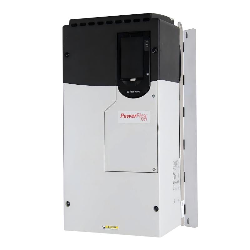
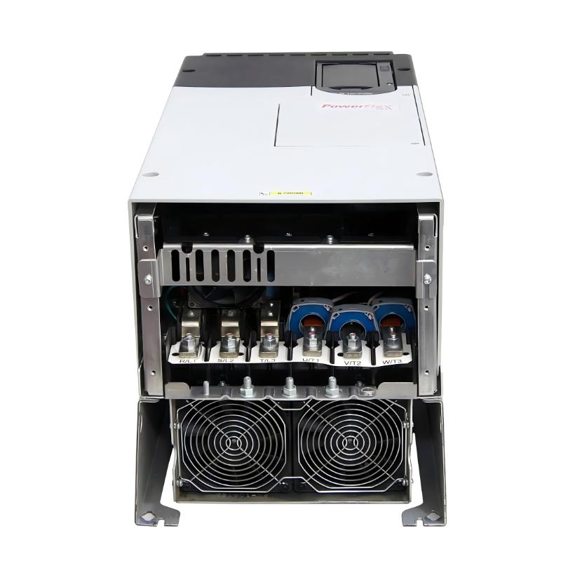
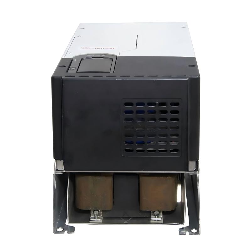
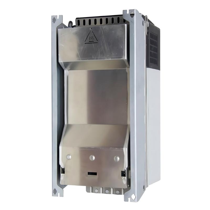
- Allen Bradley
- 20F1ANC170JN0NNNNN
- PowerFlex 753 AC Drive
- USA
- 665.5 x 308 x 346.4 mm
- 38.6 kg
- Xiamen, China
- New & In Stock
- T/T, PayPal, Western Union
- 1 Year
- 1-3 Working Days
- DHL, UPS, TNT, FedEx and EMS.
- 24-Hour Service
- COO
- 54
Our advantage

Global Logistics
We have a 10-year logistics and express cooperation agreement, so our products can be shipped to any place in the world.

Brand new and original
Our products are imported in bulk from the place of origin. Because of the cooperative relationship, our products are all original and 100% new.

24-hour service
We provide 7*24 hours service to our customers. We will be there whenever you need us.

Price advantage
All our products are priced very favorably because we have our own warehouse and supply.
| Company Information | |||
| [email protected] | |||
| Mobile | +8615980777398 | ||
| +8615980777398 | |||
| 15980777398 |
Product Overview
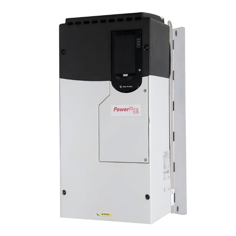
The Allen Bradley 20F1ANC170JN0NNNNN PowerFlex 753 AC Drive is an industrial variable-speed drive designed for controlling three-phase AC motors in automated machinery, production lines, material-handling equipment, pumps, fans, and process applications.
The model belongs to the PowerFlex 753 family and uses forced-air cooling. The verified product configuration is a 400 VAC, three-phase AC-input drive with precharge, 170 A output current, 90 kW normal-duty rating, 75 kW heavy-duty rating, Frame 6 construction, embedded I/O, filtered input, and no dynamic-braking transistor. The configuration is specified as IP20/IP00, NEMA/UL Open Type, with no HIM included.
The dimensions supplied for this product are 665.5 × 308 × 346.4 mm, with a listed product weight of 38.6 kg. The dimensions are also consistent with current product information for this catalog number.
The PowerFlex 753 is designed to operate as the motor-control layer within an industrial automation system. It can receive commands from a PLC or other control equipment and regulate motor operation according to configured parameters.
Product Identification
| Parameter | Specification |
|---|---|
| Manufacturer | Allen Bradley |
| Product Family | PowerFlex 753 |
| Model | 20F1ANC170JN0NNNNN |
| Product Type | PowerFlex 753 AC Drive |
| Input Type | AC Input with Precharge |
| Input Voltage | 400 VAC |
| Input Phase | 3 Phase |
| Output Current | 170 A |
| Normal-Duty Rating | 90 kW |
| Heavy-Duty Rating | 75 kW |
| Cooling | Forced Air |
| Frame Size | Frame 6 |
| Enclosure | IP20/IP00, NEMA/UL Open Type |
| Dynamic Braking | None |
| Embedded I/O | Yes |
| Dimensions | 665.5 × 308 × 346.4 mm |
| Weight | 38.6 kg |
| HIM | Not Included |
The electrical configuration above is based on the identified catalog-number configuration; the supplied dimensions and weight are retained as provided for this product listing.
Technical Specifications
| Technical Item | Specification |
|---|---|
| Brand | Allen Bradley |
| Series | PowerFlex 753 |
| Catalog Number | 20F1ANC170JN0NNNNN |
| Drive Type | AC Variable-Speed Drive |
| Voltage Class | 400 VAC |
| Input | 3-Phase AC |
| Output Current | 170 A |
| Normal-Duty Power | 90 kW |
| Heavy-Duty Power | 75 kW |
| Cooling Method | Forced Air |
| Frame | 6 |
| Input Configuration | AC Input with Precharge |
| DC Terminals | None |
| Dynamic Braking Transistor | None |
| EMC Filtering | Filtered |
| CM Jumper | Installed |
| Enclosure Rating | IP20/IP00 |
| Enclosure Type | NEMA/UL Open Type |
| Embedded I/O | Included |
| Dimensions | 665.5 × 308 × 346.4 mm |
| Weight | 38.6 kg |
The manufacturer’s current product description identifies this exact model as a 170 A, 400 VAC, three-phase, Frame 6 PowerFlex 753 with 90 kW normal-duty and 75 kW heavy-duty ratings.
What Is the Allen Bradley 20F1ANC170JN0NNNNN?
The 20F1ANC170JN0NNNNN is a high-power configuration of the Allen Bradley PowerFlex 753 AC Drive family.
Its primary function is to regulate the electrical power delivered to an AC motor so that the motor can operate at controlled speeds and under controlled acceleration and deceleration profiles.
A simplified industrial architecture is:
Three-Phase AC Supply
↓
PowerFlex 753
↓
AC Motor
↓
Mechanical Load
The drive can simultaneously communicate with the machine control system:
PLC / Controller
↓
Run Command + Speed Reference
↓
PowerFlex 753
↓
Motor
This architecture allows the controller to manage the machine sequence while the drive manages motor operation.
Working Principle
The basic power-conversion process can be represented as:
AC Input
↓
Input Power Stage
↓
DC Bus
↓
Power Switching
↓
Variable AC Output
↓
Motor
The drive changes the electrical conditions supplied to the motor according to its configured operating mode and commands.
This allows the motor to accelerate and decelerate in a controlled manner rather than being subjected to an uncontrolled direct start.
For industrial machinery, this can help coordinate motor speed with the production process.
400 VAC and 170 A Configuration
The 20F1ANC170JN0NNNNN is identified as a 400 VAC, three-phase, 170 A configuration.
Its specified ratings include:
- 90 kW normal duty
- 75 kW heavy duty
- 170 A output current
- 400 VAC input
- Three-phase operation
- Frame 6
- Forced-air cooling
These values are important when selecting the motor, protective equipment, cabinet, cables, and associated electrical infrastructure.
The drive should not be selected only by motor horsepower. Motor current, duty cycle, overload requirements, acceleration characteristics, environmental conditions, and application load profile should also be considered.
Role in Industrial Automation
The PowerFlex 753 can function as the motor-control layer below a PLC.
A typical control structure is:
HMI
↓
PLC
↓
PowerFlex 753
↓
AC Motor
↓
Mechanical Equipment
The PLC determines when the machine should start, stop, accelerate, decelerate, or change speed. The drive interprets the relevant commands and controls the motor.
The drive can also be integrated with industrial communication systems through suitable communication hardware.
Typical Industrial Applications
The 20F1ANC170JN0NNNNN can be considered for applications such as:
- Large conveyor systems
- Material-handling machinery
- Industrial pumps
- Fans
- Blowers
- Production machinery
- Process equipment
- Packaging lines
- Manufacturing systems
- Industrial mixers
- Automated processing equipment
- Large machine tools
- Industrial ventilation systems
- General-purpose motor applications
The appropriate application depends on the motor rating, load characteristics, environmental conditions, control method, and required duty cycle.
Installation Considerations
1. Verify the Catalog Number
Before installation, verify:
Allen Bradley 20F1ANC170JN0NNNNN
The catalog number should match the approved electrical design.
This is particularly important because similar PowerFlex 753 catalog numbers can have different voltage, braking, filtering, and hardware configurations.
2. Verify Electrical Ratings
Confirm that the electrical system is suitable for the drive configuration.
The identified configuration uses:
400 VAC / 3 Phase / 170 A
and is rated at:
90 kW Normal Duty / 75 kW Heavy Duty.
The incoming power system, protective equipment, motor, and wiring should be selected accordingly.
3. Check the Physical Dimensions
The supplied dimensions are:
665.5 × 308 × 346.4 mm
The cabinet should provide additional space for:
- Cable routing
- Cooling airflow
- Maintenance
- Terminal access
- Communication wiring
- Inspection
- Safe removal
Do not design the enclosure around the exact external dimensions without considering service clearance.
4. Consider the Drive Weight
The supplied product weight is:
38.6 kg
This is a substantial mechanical load.
The mounting plate and cabinet structure should be capable of securely supporting the drive.
During installation or replacement, appropriate mechanical handling procedures should be used.
5. Verify Cooling
The identified configuration uses forced-air cooling.
The cabinet therefore needs an appropriate thermal-management strategy.
Check:
- Airflow
- Cooling fans
- Ventilation
- Cabinet temperature
- Dust accumulation
- Air passages
Blocked airflow can increase drive temperature and contribute to protective trips or shortened component life.
6. Verify Grounding
Proper protective grounding should be established before energizing the drive.
Grounding is important for:
- Personnel safety
- Electrical noise management
- Equipment protection
- Shielding performance
- Communication stability
7. Connect Incoming Power
Connect the incoming power according to the approved electrical drawings.
Before energization, verify:
- Voltage
- Phase
- Protective devices
- Terminal connections
- Grounding
- Cable routing
8. Connect the Motor
Connect the motor according to the approved machine wiring.
Inspect:
- Motor phase connections
- Cable insulation
- Motor grounding
- Terminal tightness
- Cable routing
- Motor condition
9. Connect Control and Communication Wiring
Depending on the application, the drive may use:
- Digital inputs
- Digital outputs
- Analog signals
- Start/stop commands
- Speed references
- Communication modules
- Feedback devices
- PLC control
Because the specified configuration has no HIM, commissioning and configuration should be planned around the available external programming and communication methods.
Pre-Commissioning Checklist
| Item | Check |
|---|---|
| Catalog Number | 20F1ANC170JN0NNNNN |
| Input Voltage | 400 VAC |
| Input Phase | 3 Phase |
| Output Current | 170 A |
| Motor Rating | Compatible |
| Mounting | Secure |
| Grounding | Connected |
| Input Wiring | Correct |
| Motor Wiring | Correct |
| Cooling | Adequate |
| Control Wiring | Correct |
| Communication | Correct |
| Protective Devices | Installed |
| Cabinet | Suitable |
Commissioning Procedure
Step 1 — Inspect the Installation
Confirm that mechanical and electrical installation is complete.
Step 2 — Verify Motor Data
Obtain the motor nameplate information.
Typical information includes:
- Voltage
- Current
- Frequency
- Power
- Speed
- Motor connection
Step 3 — Configure the Drive
Enter the appropriate motor and application parameters using the selected configuration method.
Step 4 — Select the Command Source
Determine whether the drive receives commands from:
- Local configuration
- Hardwired control
- PLC
- Communication network
- Other control equipment
Step 5 — Configure the Speed Reference
Select the appropriate speed-reference source.
Step 6 — Configure Acceleration
Set an acceleration profile suitable for the motor and mechanical load.
Step 7 — Configure Deceleration
Set a suitable deceleration profile.
Step 8 — Perform a Controlled Test
Start the motor under controlled conditions.
Check:
- Direction
- Current
- Speed
- Drive status
- Vibration
- Noise
Step 9 — Test Under Load
Gradually introduce the mechanical load.
Monitor motor current and drive status.
Step 10 — Test Automation Control
Verify PLC commands, speed references, status signals, and communication.
Step 11 — Back Up Parameters
Save the final operating configuration.
Troubleshooting Guide
Problem 1 — Drive Does Not Start
Possible causes:
- No input power
- Incorrect power wiring
- Open protective device
- Incorrect command source
- Active fault
- Drive enable condition not satisfied
Check:
Power → Drive Status → Command Source → Enable → Fault History
Problem 2 — Motor Does Not Run
Possible causes:
- Missing run command
- Incorrect control source
- Incorrect speed reference
- Active interlock
- Motor wiring problem
- Drive fault
Verify the complete command path from the PLC or control system to the motor.
Problem 3 — Overcurrent During Acceleration
Possible causes:
- Excessive load
- Acceleration too fast
- Incorrect motor data
- Mechanical obstruction
- Motor problem
Check both electrical configuration and mechanical loading.
Problem 4 — Overcurrent During Normal Running
Possible causes:
- Excessive process load
- Mechanical friction
- Motor fault
- Incorrect motor configuration
- Mechanical obstruction
Compare the motor current with the normal operating condition.
Problem 5 — Overvoltage During Deceleration
Possible causes:
- Deceleration too short
- High-inertia load
- Regenerative energy
- Braking arrangement unsuitable for the application
Review the deceleration profile and mechanical load characteristics.
The specified catalog configuration has no dynamic-braking transistor, so braking requirements should be considered carefully when designing applications involving substantial regenerative energy.
Problem 6 — Drive Overheating
Possible causes:
- Cooling fan problem
- Blocked airflow
- High cabinet temperature
- Excessive load
- Dust contamination
- Inadequate cabinet thermal design
Check the cooling system before assuming an internal drive failure.
Problem 7 — Motor Runs at Incorrect Speed
Possible causes:
- Incorrect speed reference
- Incorrect scaling
- Incorrect motor parameters
- Incorrect command source
- Communication problem
Compare the commanded speed with the actual motor behavior.
Problem 8 — Motor Speed Is Unstable
Possible causes:
- Unstable reference
- Incorrect control parameters
- Communication instability
- Feedback problem
- Variable mechanical load
Determine whether the source is the controller, drive, feedback system, or mechanical process.
Problem 9 — Motor Vibrates Excessively
Possible causes:
- Mechanical imbalance
- Motor mounting problem
- Bearing condition
- Mechanical resonance
- Incorrect motor configuration
- Electrical interference
Inspect the motor and mechanical system as well as the drive.
Problem 10 — PLC Cannot Control the Drive
Possible causes:
- Incorrect communication configuration
- Network problem
- Incorrect command source
- PLC logic problem
- Incorrect speed-reference source
- Drive configuration mismatch
Trace:
PLC → Network → Drive → Motor
Problem 11 — Communication Is Intermittent
Possible causes:
- Damaged cable
- Loose connector
- Electrical interference
- Incorrect network settings
- Network hardware problem
Start with the physical network connection before modifying software parameters.
Problem 12 — Drive Trips When Load Is Applied
Possible causes:
- Mechanical overload
- Motor overload
- Excessive acceleration
- Mechanical obstruction
- Process load increase
Compare operation with and without the mechanical load.
Problem 13 — Drive Trips After Extended Operation
Possible causes:
- Thermal accumulation
- Cooling problem
- Long-term overload
- High ambient temperature
- Motor overheating
- Intermittent electrical connection
Record the conditions immediately before the fault.
Systematic Diagnostic Workflow
For recurring problems, use a structured sequence:
Incoming Power
↓
Drive Status
↓
Fault History
↓
Motor Parameters
↓
Command Source
↓
Speed Reference
↓
Motor Wiring
↓
Motor Condition
↓
Cooling
↓
Mechanical Load
↓
Communication
↓
PLC Logic
This approach helps prevent unnecessary replacement of a functioning drive when the actual problem is located elsewhere in the system.
Preventive Maintenance
Drive and Cabinet
Inspect regularly for:
- Dust
- Contamination
- Loose connections
- Physical damage
- Overheating
- Cooling obstruction
Forced-Air Cooling
Because this configuration uses forced-air cooling, inspect the cooling system as part of routine maintenance.
Check:
- Cooling airflow
- Fan operation
- Air passages
- Cabinet temperature
- Dust accumulation
Electrical Connections
Inspect:
- Input terminals
- Motor terminals
- Grounding
- Control wiring
- Communication connections
Motor
Monitor:
- Current
- Temperature
- Vibration
- Noise
- Mechanical load
Configuration
Maintain backups of:
- Motor parameters
- Drive parameters
- Command source
- Speed reference
- Communication settings
- PLC configuration
Preventive Maintenance Checklist
| Area | Maintenance Action |
|---|---|
| Drive Housing | Inspect for damage |
| Mounting | Verify mechanical security |
| Input Wiring | Inspect terminals |
| Motor Wiring | Check connections |
| Grounding | Verify grounding |
| Cooling Fan | Check operation |
| Airflow | Keep passages clear |
| Cabinet | Monitor temperature |
| Motor Current | Monitor abnormal increases |
| Motor Temperature | Check operating condition |
| Vibration | Monitor changes |
| Communication | Verify stability |
| Fault History | Review recurring events |
| Parameters | Maintain current backup |
Replacement Procedure
Step 1 — Back Up the Configuration
Save the existing drive parameters before removal.
Step 2 — Record Wiring
Document:
- Incoming power
- Motor wiring
- Ground
- Control wiring
- Communication
- Feedback connections
Step 3 — Stop the Machine
Bring the equipment to a safe state.
Step 4 — Isolate Power
Disconnect electrical power according to the approved site safety procedure.
Allow the required discharge period and verify the appropriate safe electrical condition before accessing power connections.
Step 5 — Remove the Existing Drive
Disconnect wiring and remove the drive.
The supplied weight is 38.6 kg, so appropriate mechanical handling should be planned.
Step 6 — Inspect the Cabinet
Check:
- Mounting plate
- Fasteners
- Cable condition
- Grounding
- Cooling
- Adjacent equipment
Step 7 — Install the Replacement
Secure the 20F1ANC170JN0NNNNN in the designated position.
Step 8 — Reconnect Wiring
Reconnect:
- Input power
- Motor
- Grounding
- Control
- Communication
- Feedback where applicable
Step 9 — Restore Configuration
Load the validated parameters.
Step 10 — Verify Motor Data
Confirm that the configured motor information matches the installed motor.
Step 11 — Perform Controlled Testing
Check:
- Motor direction
- Current
- Speed
- Drive status
- Vibration
- Noise
Step 12 — Test PLC Control
Verify commands, references, status signals, and communication.
Step 13 — Perform Loaded Testing
Gradually return the machine to normal operation.
Compatible System Components
The PowerFlex 753 architecture can be integrated with several types of automation equipment:
| Component Type | Typical Role |
|---|---|
| PLC | Machine sequence control |
| HMI | Operator interface |
| Communication Module | Network integration |
| Encoder / Feedback Module | Motor or speed feedback |
| I/O Module | Hardwired control |
| Circuit Protection | Electrical protection |
| Disconnect | Power isolation |
| AC Motor | Mechanical power source |
| External Braking Equipment | Braking applications where required |
| Control Cabinet | Mechanical and environmental protection |
The specific option modules and system components should be selected according to the application and required functions.
Key Advantages
- PowerFlex 753 industrial AC drive platform
- 400 VAC three-phase configuration
- 170 A output-current rating
- 90 kW normal-duty rating
- 75 kW heavy-duty rating
- Frame 6 construction
- Forced-air cooling
- Embedded I/O
- Filtered configuration
- AC input with precharge
- No DC terminals in this configuration
- IP20/IP00 NEMA/UL Open Type construction
- Suitable for PLC-based automation
- Specified dimensions of 665.5 × 308 × 346.4 mm
- Supplied weight of 38.6 kg
- Suitable for large industrial motor-control applications
The electrical characteristics and configuration are supported by the current product information for the exact catalog number.
Frequently Asked Questions
What is the Allen Bradley 20F1ANC170JN0NNNNN?
The 20F1ANC170JN0NNNNN is an Allen Bradley PowerFlex 753 AC Drive configured for 400 VAC three-phase operation and 170 A output current.
What is the normal-duty rating?
The identified configuration is rated at 90 kW normal duty.
What is the heavy-duty rating?
The identified configuration is rated at 75 kW heavy duty.
What is the output current?
The catalog configuration has an output-current rating of 170 A.
What are the dimensions?
The supplied dimensions are:
665.5 × 308 × 346.4 mm
What is the weight?
The supplied product weight is:
38.6 kg
What type of cooling does this drive use?
The identified configuration uses forced-air cooling.
Does this model have a dynamic-braking transistor?
No. The exact 20F1ANC170JN0NNNNN configuration is specified without a dynamic-braking transistor.
Does the drive include a HIM?
The identified configuration is specified with a blank/no HIM configuration.
Why is the drive overheating?
Check forced-air cooling, cabinet temperature, airflow, fan condition, dust accumulation, motor load, and installation conditions.
Why does the drive trip during acceleration?
Possible causes include excessive mechanical load, overly aggressive acceleration, incorrect motor parameters, mechanical obstruction, or motor problems.
Why does the drive trip during deceleration?
A high-inertia load can return energy to the drive. Because this exact configuration has no dynamic-braking transistor, the application should be evaluated carefully when substantial regenerative energy is expected.
Can it be integrated with a PLC?
Yes. The PowerFlex 753 family is designed for integration into industrial automation architectures, with built-in I/O and available communication and option modules.
Conclusion
The Allen Bradley 20F1ANC170JN0NNNNN PowerFlex 753 AC Drive is a high-capacity industrial variable-speed drive configured for 400 VAC three-phase input, 170 A output current, 90 kW normal-duty operation, and 75 kW heavy-duty operation. The exact configuration uses forced-air cooling, embedded I/O, filtered input, AC input with precharge, Frame 6 construction, and no dynamic-braking transistor.
With supplied dimensions of 665.5 × 308 × 346.4 mm and a listed weight of 38.6 kg, the drive requires careful attention to cabinet structure, mechanical mounting, cooling, cable routing, and safe handling.
Installation should begin with verification of the catalog number and electrical ratings. The 400 VAC supply, 170 A drive rating, motor requirements, protective devices, grounding, and cabinet cooling should all be confirmed before energization.
During commissioning, accurate motor data and correct command and speed-reference sources are essential. A controlled low-speed test should be completed before full-load operation so that motor direction, current, acceleration, deceleration, communication, and mechanical response can be verified.
For troubleshooting, technicians should evaluate the complete system rather than automatically assuming a drive fault. Power supply, configuration, control commands, communication, motor wiring, motor condition, cooling, and mechanical loading can all contribute to abnormal operation.
Routine preventive maintenance should focus on forced-air cooling, cabinet temperature, electrical connections, motor condition, communication, fault history, and parameter backups. A structured maintenance program can help reduce unexpected downtime and simplify future drive replacement.
With correct installation, commissioning, preventive maintenance, and systematic fault diagnosis, the Allen Bradley 20F1ANC170JN0NNNNN PowerFlex 753 AC Drive provides a robust solution for large industrial AC motor-control applications.