

ProductPRODUCT
Featured products
Contact Us
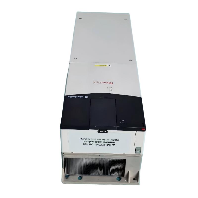
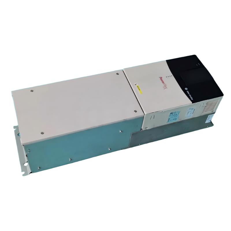
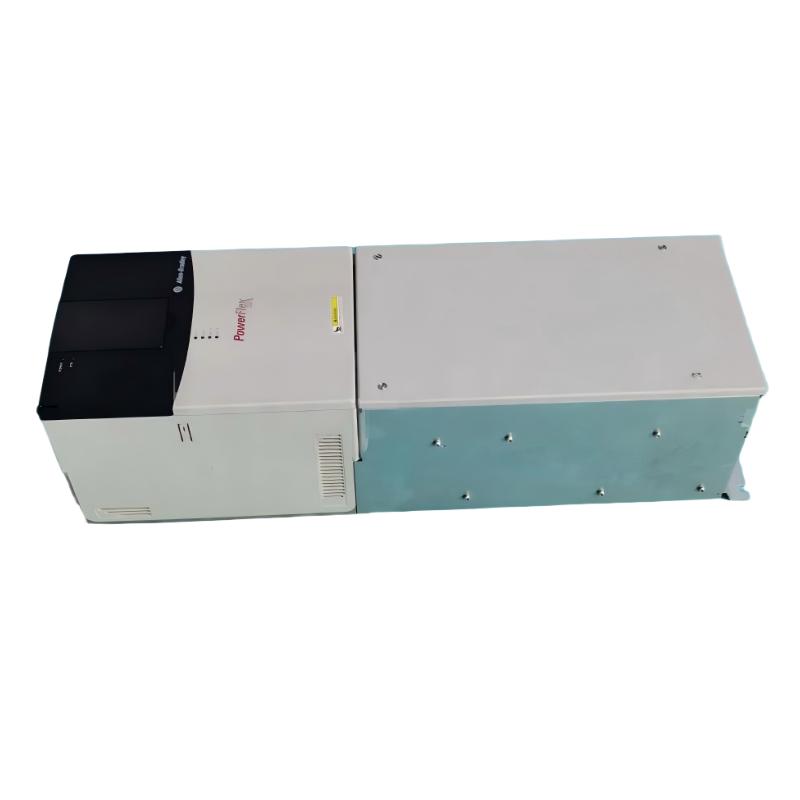
- Allen Bradley
- 20BC125A3ANNANC0
- PowerFlex AC Drive
- USA
- 689.6 × 308.9 × 275.4 mm
- 37.14kg
- Xiamen, China
- New & In Stock
- T/T, PayPal, Western Union
- 1 Year
- 1-3 Working Days
- DHL, UPS, TNT, FedEx and EMS.
- 24-Hour Service
- COO
- 2
Our advantage

Global Logistics
We have a 10-year logistics and express cooperation agreement, so our products can be shipped to any place in the world.

Brand new and original
Our products are imported in bulk from the place of origin. Because of the cooperative relationship, our products are all original and 100% new.

24-hour service
We provide 7*24 hours service to our customers. We will be there whenever you need us.

Price advantage
All our products are priced very favorably because we have our own warehouse and supply.
| Company Information | |||
| [email protected] | |||
| Mobile | +8615980777398 | ||
| +8615980777398 | |||
| 15980777398 |
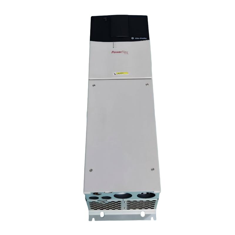
Allen-Bradley 20BC125A3ANNANC0 AC Drive: Product Overview, Technical Specifications, Applications, Advantages, and Related Models
1. Product Overview
The 20BC125A3ANNANC0 is an industrial AC variable-frequency drive in the PowerFlex 700 series, designed to regulate the speed and operation of three-phase AC motors. It is intended for industrial machinery, production lines, and process equipment that require adjustable motor speed, controlled acceleration, and integration with an industrial control system.
This model belongs to the 400 V-class drive range and has a rated output current of 125 A. Its associated ratings are 55 kW for normal-duty applications and 45 kW for heavy-duty applications. The appropriate rating depends on the motor’s rated current, load torque, overload requirements, and operating cycle.
The 20BC125A3ANNANC0 is a specific catalog configuration, so its hardware options should be checked carefully when sourcing a replacement. Communication interface, control mode, feedback capability, braking hardware, and operator interface can differ between models that otherwise have similar electrical ratings.
The PowerFlex 700 20B family is discontinued. The model is therefore especially relevant to existing installations, equipment maintenance, spare-parts planning, and replacement projects where compatibility with the original drive is important.
2. Product Identification and Main Specifications
|
Item |
Specification |
|---|---|
|
Model |
20BC125A3ANNANC0 |
|
Brand |
Allen-Bradley |
|
Product series |
PowerFlex 700 |
|
Product family |
20B |
|
Product type |
Industrial AC variable-frequency drive |
|
Rated input voltage class |
380–480 V AC |
|
Nominal voltage reference |
400 V AC |
|
Input phase |
Three-phase |
|
Output phase |
Three-phase |
|
Rated output current |
125 A |
|
Normal-duty rating |
55 kW |
|
Heavy-duty rating |
45 kW |
|
Control configuration |
Vector-control variant; verify against the complete catalog code |
|
Control I/O |
24 V I/O configuration |
|
Communication module |
Not included in the previously identified configuration |
|
Brake IGBT |
Not installed in the previously identified configuration |
|
Internal braking resistor |
Not included |
|
Motor feedback |
No feedback option specified |
|
Enclosure classification |
IP20 / NEMA Type 1 |
|
Conformal coating |
Confirm against the exact catalog configuration |
|
EMC filter |
Confirm against the exact catalog configuration |
|
Dimensions (H × W × D) |
Verify exact mechanical drawing; related 125 A variants may differ |
|
Weight (kg) |
Verify exact unit; related variants are not guaranteed to have identical mass |
|
Lifecycle status |
Discontinued |
The precise catalog suffix is important. The electrical rating alone does not establish the communication, feedback, braking, or front-panel configuration, and these differences can affect whether the drive can replace another unit without changes.
3. Confirmed Configuration Details
The full configuration description for this model identifies a vector-control drive with 24 V I/O, a full numeric LCD keypad, conformal coating, and a second-environment EMC filter. It does not include a brake IGBT, a drive-mounted braking resistor, a communication module, or a motor-feedback option.
|
Parameter |
Specification |
|---|---|
|
Model |
20BC125A3ANNANC0 |
|
Drive type |
PowerFlex 700 AC drive |
|
Input voltage |
400 V AC |
|
Input phase |
Three-phase |
|
Rated output current |
125 A |
|
Normal-duty rating |
55 kW |
|
Heavy-duty rating |
45 kW |
|
Control method |
Vector control |
|
Control I/O |
24 V I/O |
|
Operator interface |
LCD display with full numeric keypad |
|
Brake IGBT |
Not installed |
|
Drive-mounted braking resistor |
Not included |
|
Communication module |
Not included |
|
Motor feedback |
No feedback option |
|
EMC filter |
Second-environment filter |
|
Common-mode choke |
Included in the specified filter configuration |
|
Enclosure |
IP20 / NEMA Type 1 |
|
Conformal coating |
Included |
|
Frame size |
Frame 5 |
|
Dimensions (H × W × D) |
689.6 × 308.9 × 275.4 mm |
|
Weight |
37.19 kg |
4. Detailed Electrical Parameters
4.1 Input and Output Ratings
|
Parameter |
Specification |
|---|---|
|
Model |
20BC125A3ANNANC0 |
|
Input voltage class |
380–480 V AC |
|
Nominal input voltage |
400 V AC |
|
Input supply |
Three-phase AC |
|
Output supply |
Three-phase variable-frequency AC |
|
Rated output current |
125 A |
|
Normal-duty motor rating |
55 kW |
|
Heavy-duty motor rating |
45 kW |
|
Nominal mains frequency |
50/60 Hz class; verify permitted range for the installation |
|
Output frequency |
Depends on drive configuration and programmed operating limits |
|
Motor-control method |
Vector control |
|
Feedback option |
None specified |
|
Braking transistor |
Not installed |
|
Internal braking resistor |
Not included |
|
Dimensions (H × W × D) |
689.6 × 308.9 × 275.4 mm |
|
Weight |
37.19 kg |
The 55 kW normal-duty and 45 kW heavy-duty ratings should not be treated as interchangeable ratings for every operating condition. Normal-duty operation generally applies to applications with less demanding overload requirements, while heavy-duty operation is intended for more demanding torque and overload profiles.
The correct selection depends on motor nameplate current, load inertia, acceleration time, overload duration, ambient temperature, and the machine’s operating cycle. A motor with a nominal rating within the stated kilowatt range may still be unsuitable if its current demand or starting torque exceeds the drive’s permitted limits.
4.2 Control and Operator Interface
|
Parameter |
Specification |
|---|---|
|
Model |
20BC125A3ANNANC0 |
|
Control mode |
Vector control |
|
Control I/O |
24 V I/O |
|
Operator display |
LCD |
|
Keypad |
Full numeric keypad |
|
Parameter entry |
Through the supported operator interface or compatible configuration tools |
|
Communication module |
Not included |
|
Analog and digital I/O |
Refer to the applicable terminal specification |
|
Motor feedback |
No feedback option |
|
Dimensions (H × W × D) |
689.6 × 308.9 × 275.4 mm |
|
Weight |
37.19 kg |
The full numeric keypad provides a local interface for viewing drive information, entering parameters, and carrying out supported operating commands. This can be useful during installation, troubleshooting, and maintenance.
The 24 V I/O arrangement supports conventional industrial control wiring. Actual terminal functions depend on the wiring and programmed configuration, so the terminal diagram and applicable manual should be checked before connecting external control signals.
Because the specified configuration does not include a communication module, network-based control should not be assumed to be available without an appropriate interface or a different catalog configuration.
4.3 Protection and Environmental Parameters
|
Parameter |
Specification |
|---|---|
|
Model |
20BC125A3ANNANC0 |
|
Enclosure rating |
IP20 |
|
NEMA classification |
Type 1 |
|
Conformal coating |
Included |
|
EMC filter |
Second-environment configuration |
|
Common-mode choke |
Included in the specified filter configuration |
|
Reference ambient temperature |
Up to 50°C under specified conditions; derating may apply |
|
Maximum altitude without derating |
Typically 1,000 m under reference conditions |
|
Relative humidity |
Non-condensing conditions required |
|
Installation environment |
Protected industrial cabinet or suitable electrical enclosure |
|
Cooling |
Maintain the specified airflow and mounting clearances |
|
Dimensions (H × W × D) |
689.6 × 308.9 × 275.4 mm |
|
Weight |
37.19 kg |
The IP20 / NEMA Type 1 enclosure is intended for an appropriate protected installation. The drive should not be exposed directly to rain, washdown, or other conditions beyond its environmental rating.
Conformal coating provides additional protection to electronic assemblies in suitable industrial environments. It does not make the drive waterproof or eliminate the need for proper enclosure design, ventilation, and maintenance.
5. Product Applications
5.1 Industrial Pumps
The drive can be used with compatible industrial pumps where the required flow rate or pressure changes during operation. Adjustable motor speed allows the pump to respond to process demand rather than running continuously at a fixed speed.
Typical applications include industrial water circulation, process-fluid transfer, cooling-water systems, and utility pumping equipment.
For variable-flow applications, speed control may reduce the need for mechanical throttling and can lower energy use when the pump operates at reduced speed. The actual benefit depends on the pump curve, operating profile, and process requirements.
5.2 Industrial Fans and Ventilation
Fans and ventilation systems often require different operating speeds depending on airflow, temperature, and production demand. A variable-frequency drive can adjust the motor speed to match these requirements.
Suitable applications may include industrial ventilation, air-handling systems, cooling fans, process exhaust equipment, and general air-circulation machinery.
The permitted speed range should be checked against fan balance, bearing limits, motor cooling, and mechanical resonance. The maximum output-frequency capability of a drive should never be taken as the safe operating limit for every connected motor.
5.3 Conveyors and Material Handling
Conveyor systems often need controlled acceleration, predictable running speed, and coordination with other production equipment. The drive can be used where its current rating and overload performance are sufficient for the motor and load.
Typical applications include assembly-line conveyors, material transfer systems, packaging equipment, sorting lines, and industrial handling machinery.
Vector control can help regulate speed under changing load conditions. However, if the machine requires rapid deceleration or frequent electrical braking, the absence of a brake IGBT and drive-mounted braking resistor must be considered.
5.4 Mixers and Agitators
Mixers and agitators may experience changing torque requirements as the density, viscosity, or quantity of material changes. Adjustable motor speed can help match the equipment’s operation to different process stages.
Applications may include mixing tanks, blending systems, process agitators, and other rotating industrial equipment.
Before selecting the drive, assess starting torque, operating torque, mechanical inertia, acceleration time, and duty cycle. Heavy or high-inertia loads may need a separate braking arrangement or a different drive configuration.
5.5 Manufacturing Machinery
The drive can form part of an industrial machine where adjustable motor speed is needed to support production requirements.
Examples include material-feeding systems, processing equipment, machine auxiliaries, and production-line machinery.
The LCD keypad can be useful for local parameter access and troubleshooting. For centralized control, the available I/O and the absence of an included communication module should be taken into account during system design.
5.6 Existing PowerFlex 700 Installations
This model is particularly relevant to maintenance and replacement work in installations already using the PowerFlex 700 series.
A like-for-like replacement may help preserve the existing cabinet arrangement and control method. Nevertheless, the full catalog number, control I/O, keypad configuration, braking hardware, feedback capability, and filter options must match the original installation.
6. Main Advantages
6.1 High-Current Motor Control
The 125 A output rating makes the drive suitable for evaluating medium- to higher-power industrial motor applications. The 55 kW normal-duty and 45 kW heavy-duty ratings provide useful starting points for assessing motor compatibility.
Final selection must account for actual motor current, overload demand, ambient conditions, and the machine’s operating cycle.
6.2 Vector-Control Operation
Vector control provides a method of regulating motor speed and torque. When the drive is configured and tuned correctly, it can help maintain stable operation as load conditions change.
This can be useful for conveyors, process machinery, and other applications where speed stability influences product quality or machine performance.
6.3 Local LCD and Numeric Keypad
The LCD display and full numeric keypad provide a local means of accessing drive information and entering parameters.
This can simplify routine commissioning and troubleshooting, particularly where a technician needs to review settings or diagnostic information at the drive itself.
6.4 Adjustable Speed and Controlled Acceleration
The drive can vary motor speed to suit different operating conditions. Controlled acceleration and deceleration can also help reduce abrupt changes in mechanical load.
These functions may reduce stress on belts, couplings, gears, and driven machinery when the drive is configured to suit the application.
6.5 EMC Filter and Common-Mode Choke
The specified EMC filter and common-mode choke help manage electromagnetic interference associated with variable-frequency drive operation.
Their effectiveness depends on correct grounding, cable shielding, cable routing, motor-cable length, and cabinet layout. Correct installation remains necessary for electromagnetic compatibility.
6.6 Conformal-Coated Electronics
The specified conformal coating can improve the resilience of electronic assemblies in certain industrial environments.
It should not be treated as a substitute for a suitable enclosure or as protection against direct water exposure, condensation, or every type of corrosive contaminant.
6.7 Useful for Maintenance of Existing Equipment
When the existing machine was designed around the same PowerFlex 700 configuration, an exact-match unit may reduce the extent of changes to wiring, parameter settings, and mounting.
Because the product family is discontinued, replacement planning should include verification of the exact unit condition and its included hardware.
7. Brand and Product Series
|
Item |
Details |
|---|---|
|
Model |
20BC125A3ANNANC0 |
|
Brand |
Allen-Bradley |
|
Product series |
PowerFlex 700 |
|
Family designation |
20B |
|
Product type |
Industrial AC variable-frequency drive |
|
Main function |
Adjustable-speed control of three-phase AC motors |
|
Nominal voltage class |
400 V AC |
|
Rated output current |
125 A |
|
Normal-duty rating |
55 kW |
|
Heavy-duty rating |
45 kW |
|
Control mode |
Vector control |
|
Operator interface |
LCD display and full numeric keypad |
|
Enclosure |
IP20 / NEMA Type 1 |
|
Dimensions (H × W × D) |
689.6 × 308.9 × 275.4 mm |
|
Weight |
37.19 kg |
|
Lifecycle |
Discontinued |
The PowerFlex 700 series was designed for industrial motor-control applications requiring configurable drive functions and a range of electrical ratings.
Models within the series can differ in current, voltage, control method, feedback, communication, braking hardware, filtering, and operator interface. The full catalog number should therefore be used when identifying a suitable replacement.
8. Five Related Models in the Same Series
The following models are closely related PowerFlex 700 variants. They provide a useful starting point for comparing electrical ratings and configuration options.
Physical specifications should be checked against each model’s mechanical drawing. Where the exact dimensions and weight are not established for the specific variant, the table marks them for verification rather than assuming that every model has identical hardware.
|
Model |
Series |
Voltage class |
Output current |
Normal-duty rating |
Heavy-duty rating |
Configuration comparison |
Dimensions (H × W × D, mm) |
Weight (kg) |
|---|---|---|---|---|---|---|---|---|
|
20BC125A3ANNANA0 |
PowerFlex 700 |
400 V class |
125 A |
55 kW |
45 kW |
Similar electrical class; verify the exact control and hardware options |
689.6 × 308.9 × 275.4, verify |
37.19, verify |
|
20BC125A3ANNACC0 |
PowerFlex 700 |
400 V class |
125 A |
55 kW |
45 kW |
Same basic rating; verify the exact control configuration |
689.6 × 308.9 × 275.4, verify |
37.19, verify |
|
20BC125A3AYNANC0 |
PowerFlex 700 |
400 V class |
125 A |
55 kW |
45 kW |
Brake IGBT configuration; check braking resistor requirements |
Verify drawing |
Verify exact unit |
|
20BC125A3AYNANA0 |
PowerFlex 700 |
400 V class |
125 A |
55 kW |
45 kW |
Alternative 125 A configuration with braking hardware; verify all options |
Verify drawing |
Verify exact unit |
|
20BC140A3ANNANC0 |
PowerFlex 700 |
400 V class |
140 A |
75 kW |
55 kW |
Higher-current and higher-power variant |
Verify drawing |
Verify exact unit |
8.1 20BC125A3ANNANA0
This model is useful for comparing the same general current and power class with a different catalog configuration. Confirm the control mode, operator interface, feedback option, and braking arrangement before considering it a replacement.
8.2 20BC125A3ANNACC0
This is another related model in the 125 A PowerFlex 700 range. The full suffix should be checked because it may identify differences in control or hardware options that affect integration with the existing system.
8.3 20BC125A3AYNANC0
This variant is worth evaluating if braking hardware is required. Confirm the brake IGBT configuration and whether the application also requires a separate braking resistor or other braking equipment.
8.4 20BC125A3AYNANA0
This model provides another comparison point in the same current class. The precise control configuration and braking hardware should be checked against the application before purchase.
8.5 20BC140A3ANNANC0
The 140 A variant has a higher current rating and a higher stated power rating. It may be considered when the application requires additional capacity, but the motor, cabling, upstream protection, and cabinet cooling must all be reassessed.
A higher-rated drive is not automatically a better replacement. It must still be suitable for the motor and the machine’s operating requirements.
9. Five Other Models from the Same Brand
The following models belong to other drive families under the same brand. They may be relevant for compact machinery, general-purpose motor control, or modernization projects, but they are not automatically direct replacements for the 20BC125A3ANNANC0.
|
Model |
Product family |
Voltage class |
Typical application |
Electrical rating |
Dimensions (H × W × D, mm) |
Weight (kg) |
|---|---|---|---|---|---|---|
|
25B-D017N104 |
PowerFlex 525 |
480 V class |
Compact machinery and general-purpose speed control |
Verify exact current and power rating |
Verify exact drawing |
Verify exact unit |
|
25B-D024N104 |
PowerFlex 525 |
480 V class |
General industrial motor control |
Verify exact current and power rating |
Verify exact drawing |
Verify exact unit |
|
22B-D017N104 |
PowerFlex 40 |
480 V class |
Simpler variable-speed motor applications |
Verify exact current and power rating |
Verify exact drawing |
Verify exact unit |
|
20F11NC015JA0NNNNN |
PowerFlex 753 |
Confirm full configuration |
Industrial drive systems and process equipment |
Verify exact catalog rating |
Verify exact drawing |
Verify exact unit |
|
20G11NC022JA0NNNNN |
PowerFlex 755 |
Confirm full configuration |
Advanced industrial motor-control applications |
Verify exact catalog rating |
Verify exact drawing |
Verify exact unit |
9.1 PowerFlex 525 — 25B-D017N104
The PowerFlex 525 family is generally suited to compact machine designs and general-purpose motor-control applications. It can be considered where a smaller drive meets the motor’s current and overload requirements.
Its rating may be substantially lower than the target drive’s 125 A output current. It should therefore be selected only after checking the motor nameplate, load characteristics, and required control functions.
9.2 PowerFlex 525 — 25B-D024N104
This is another PowerFlex 525 catalog variant that may be relevant for compact industrial equipment. Its exact voltage, current, power, and control specifications should be confirmed before selecting it for a particular motor.
It should not be treated as an equivalent replacement for a 125 A drive unless the actual application requirements are within its rated limits.
9.3 PowerFlex 40 — 22B-D017N104
The PowerFlex 40 family is associated with comparatively straightforward variable-speed motor applications. It may be suitable for auxiliary machinery or simpler equipment where its ratings and functions meet the requirement.
Because it is a different drive family, its suitability should be assessed from its own specifications rather than from brand or product-family similarity.
9.4 PowerFlex 753 — 20F11NC015JA0NNNNN
The PowerFlex 753 family can be evaluated for industrial applications requiring a configurable drive platform. The chosen configuration should match the motor current, power, voltage, control, feedback, communication, and braking requirements.
Replacing a PowerFlex 700 with another family may require changes to wiring, mounting, parameter settings, and controller integration.
9.5 PowerFlex 755 — 20G11NC022JA0NNNNN
The PowerFlex 755 family can be considered for a modernization project where the control platform and available options need to meet the machine’s requirements.
The complete ordering code must be checked before selecting a replacement. Similar brand identity does not guarantee equivalent electrical ratings or compatible communication and braking arrangements.
10. Dimensions and Weight for Installation Planning
The reference dimensions for the 20BC125A3ANNANC0 are 689.6 mm high × 308.9 mm wide × 275.4 mm deep, with a reference weight of 37.19 kg.
These figures are useful for initial cabinet layout and handling plans. The exact mechanical drawing should still be checked before the enclosure, mounting brackets, cable routing, or lifting arrangements are finalized.
|
Mechanical parameter |
Specification |
|---|---|
|
Model |
20BC125A3ANNANC0 |
|
Height |
689.6 mm |
|
Width |
308.9 mm |
|
Depth |
275.4 mm |
|
Weight |
37.19 kg |
|
Frame size |
Frame 5 |
|
Enclosure rating |
IP20 / NEMA Type 1 |
|
Mounting arrangement |
Follow the exact mechanical drawing |
|
Cabinet clearance |
Maintain the specified top, bottom, and side clearances |
|
Cooling |
Provide the required airflow |
|
Cable routing |
Allow sufficient room for power and control wiring |
|
Service access |
Ensure safe access for inspection and maintenance |
Cabinet design should account for more than the drive’s outer dimensions. The required ventilation, terminal access, cable-bending radius, and space for safe maintenance can all influence the final enclosure size.
11. Installation and Commissioning Considerations
Before installing or commissioning the drive, confirm that its electrical configuration and available functions match the motor and machine.
1. Verify the motor nameplate. Check rated voltage, current, power, frequency, and speed.
2. Confirm the duty rating. Compare the normal-duty and heavy-duty ratings with the actual torque, acceleration, and overload requirements.
3. Check the power supply. Confirm incoming voltage, grounding, protective devices, and conductor sizing.
4. Review the control terminals. Match the 24 V I/O configuration, terminal assignments, external signals, and machine interlocks.
5. Confirm communication needs. The specified configuration does not include a communication module, so network-based control may require additional hardware or a different configuration.
6. Assess braking requirements. The model has no brake IGBT and no drive-mounted braking resistor. Rapid deceleration and high-inertia loads require a separate braking assessment.
7. Check feedback requirements. If encoder feedback or closed-loop operation is necessary, confirm that the selected hardware supports it.
8. Provide appropriate environmental protection. Ensure the enclosure, ventilation, temperature, and humidity are suitable for an IP20 / NEMA Type 1 drive.
9. Set the parameters for the actual motor. Use the motor nameplate and application requirements rather than copying another drive’s settings without verification.
10. Commission under controlled conditions. Test motor direction, current, speed regulation, acceleration and deceleration, fault handling, and load response before returning the machine to normal service.
Electrical installation and commissioning should be performed by qualified personnel following the applicable safety requirements.
12. Lifecycle and Replacement Planning
The PowerFlex 700 20B family is discontinued. This should be considered when planning repairs, spare-parts inventory, and long-term maintenance.
A replacement unit should be checked for its complete catalog number, physical condition, hardware options, and included accessories. A visually similar drive may have different control I/O, communication, feedback, braking, or filtering.
Two replacement approaches are common.
Like-for-like replacement: Match the original catalog configuration as closely as possible to reduce changes to the machine’s wiring, mounting, and control logic.
Modernization: Select another drive family based on the motor and application requirements, then review any changes needed for wiring, communications, braking, parameter configuration, mounting, and commissioning.
For long-term planning, consider the expected service life of the machine, the availability of compatible spare parts, the work needed to integrate a replacement, and the cost of modifying the existing control system.
13. Final Assessment
The 20BC125A3ANNANC0 is a PowerFlex 700 AC drive rated for 400 V three-phase operation, with a rated output current of 125 A, a 55 kW normal-duty rating, and a 45 kW heavy-duty rating.
Its specified configuration includes vector control with 24 V I/O, an LCD display with a full numeric keypad, conformal coating, and a second-environment EMC filter. It does not include a brake IGBT, a drive-mounted braking resistor, a communication module, or a motor-feedback option.
The reference dimensions are 689.6 × 308.9 × 275.4 mm, and the reference weight is 37.19 kg. These figures should be confirmed against the exact unit before finalizing cabinet design or installation arrangements.
The most important selection factors are the motor’s current and duty requirements, the control functions needed by the machine, the absence of braking and communication hardware in this configuration, and the discontinued status of the product family.
For a replacement project, match the complete catalog number and verify the physical and electrical specifications before purchase. For a modernization project, evaluate the required current and power first, then compare control, feedback, communication, braking, mounting, and environmental requirements.