

ProductPRODUCT
Featured products
Contact Us
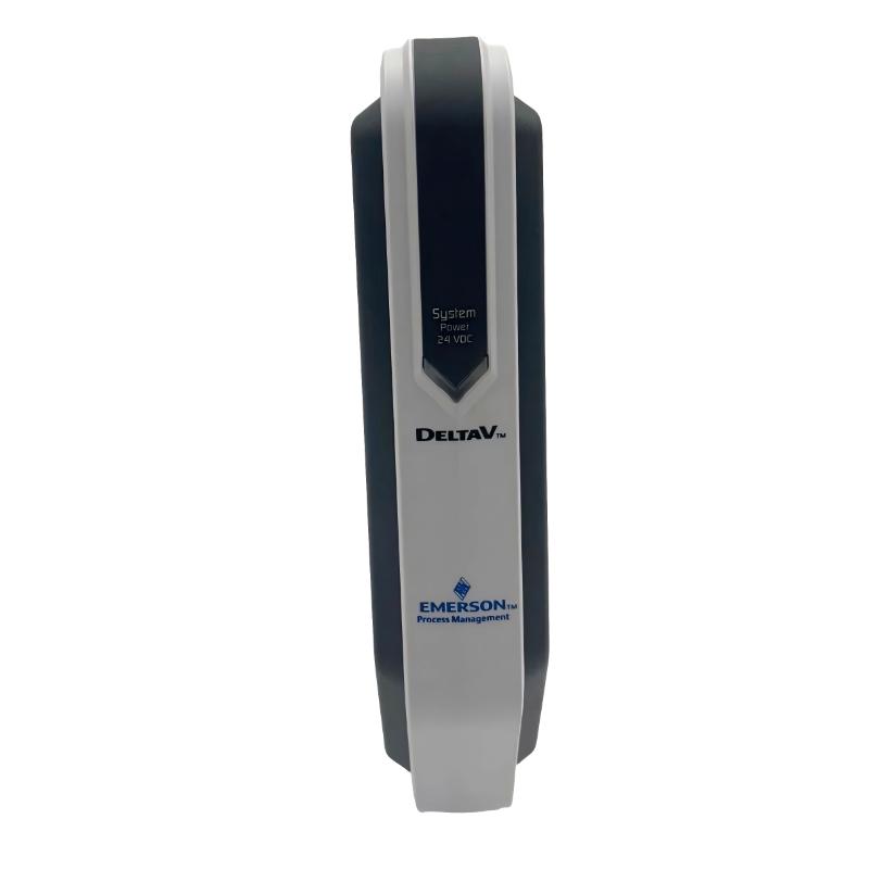
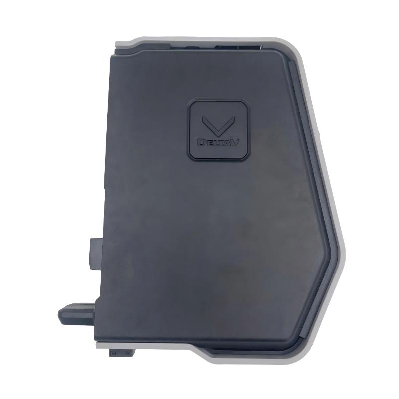
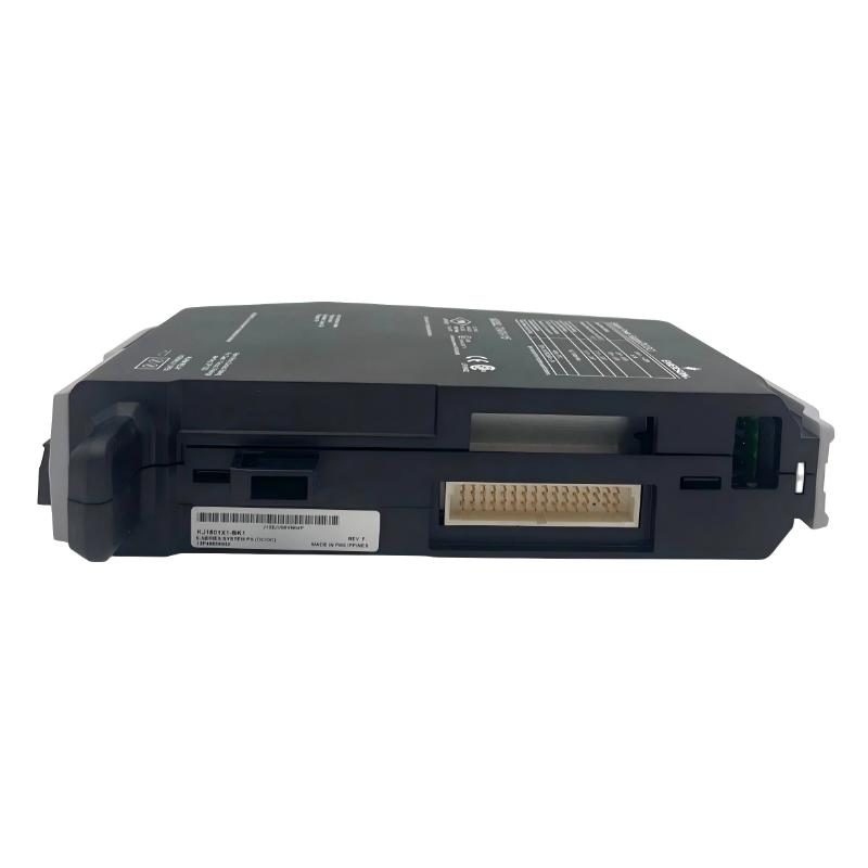
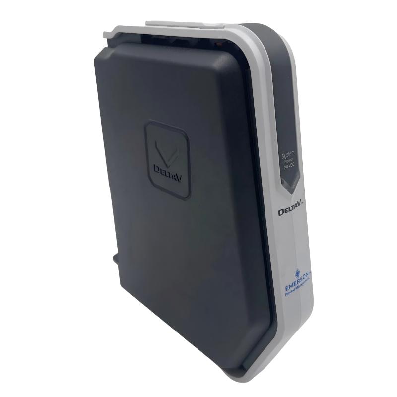
- Emerson
- VE5109
- DC to DC System Power Supply
- USA
- 160.6 × 41.8 × 139.1 mm
- 1.36 kg
- Xiamen, China
- New & In Stock
- T/T, PayPal, Western Union
- 1 Year
- 1-3 Working Days
- DHL, UPS, TNT, FedEx and EMS.
- 24-Hour Service
- COO
- 6
Our advantage

Global Logistics
We have a 10-year logistics and express cooperation agreement, so our products can be shipped to any place in the world.

Brand new and original
Our products are imported in bulk from the place of origin. Because of the cooperative relationship, our products are all original and 100% new.

24-hour service
We provide 7*24 hours service to our customers. We will be there whenever you need us.

Price advantage
All our products are priced very favorably because we have our own warehouse and supply.
| Company Information | |||
| [email protected] | |||
| Mobile | +8615980777398 | ||
| +8615980777398 | |||
| 15980777398 |
Product Overview
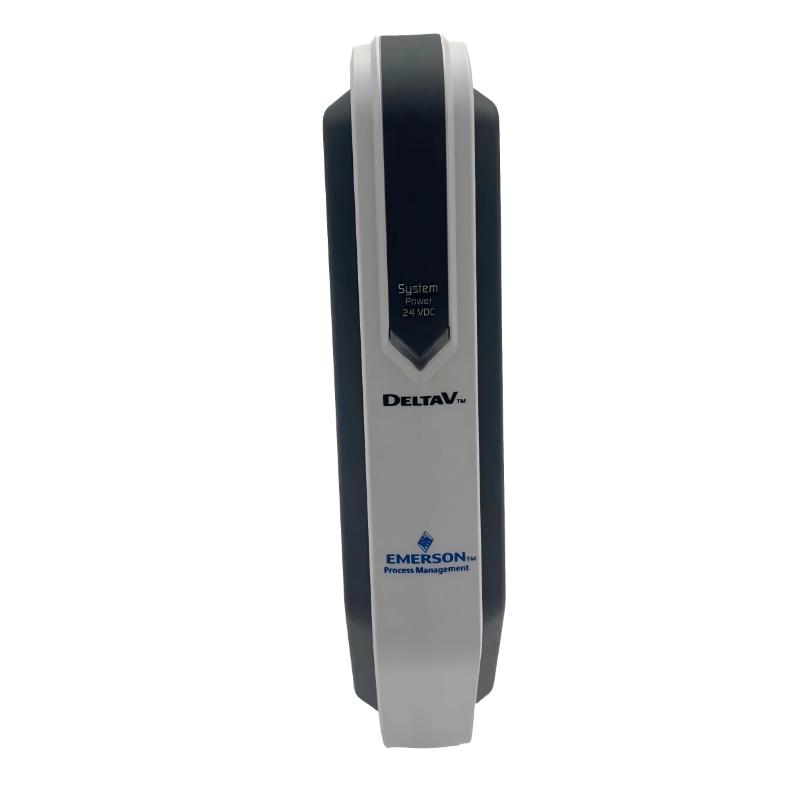
The Emerson VE5109 DeltaV M-Series DC to DC System Power Supply supplies regulated DC power to DeltaV M-Series controllers and I/O interfaces. It accepts 12 V DC or 24 V DC input power and generates the voltage rails required by the control system electronics. Within a distributed control system (DCS), this module supports the power infrastructure needed for process monitoring, controller operation, and I/O signal handling.
The VE5109 is installed in a compatible DeltaV power/controller carrier rather than functioning as a standalone power converter. The carrier provides internal power buses for the controller and I/O interfaces, reducing the need for separate external power wiring between these components. This arrangement is useful when building new control cabinets, maintaining existing M-Series installations, or expanding a process control system.
The module provides a 12 V DC output for I/O interface power and supplies the 5 V DC and 3.3 V DC rails required by the controller electronics. When supplied from a 24 V DC bulk power source, the enhanced M-Series DC/DC power supply supports up to 8.0 A on the 12 V DC I/O interface power bus within its specified operating conditions. The available output capacity must be evaluated against the actual controller, I/O carrier, and module load.
For maintenance and system upgrades, the VE5109 supports modular installation and power-system expansion. Its input compatibility allows integration with suitable 12 V DC or 24 V DC plant power arrangements, while power-status indication and relay alarm contacts help technicians identify supply-related problems. Correct carrier selection, load calculations, input wiring, and redundancy planning remain essential to maintaining the intended system availability.
Technical Specifications
| Parameter | Specification |
|---|---|
| Manufacturer | Emerson |
| Model | VE5109 |
| Product Family | DeltaV M-Series |
| Product Type | DC to DC System Power Supply |
| Power Conversion Type | DC-to-DC |
| Input Voltage | 12 V DC or 24 V DC |
| 12 V DC Input Rating | 12 V DC, -4% to +5%, at 14.8 A |
| 24 V DC Input Rating | 24 V DC ±20%, at 6.1 A |
| 12 V DC Output at 12 V DC Input | Up to 13 A at -40 to 60°C |
| 12 V DC Output at 24 V DC Input | Up to 8.0 A at -40 to 60°C |
| 12 V DC Output at 60 to 70°C | Up to 10 A with 12 V DC input or 6.0 A with 24 V DC input |
| 5 V DC Output | 2.0 A |
| 3.3 V DC Output | 2.0 A |
| Combined 5 V DC and 3.3 V DC Output Power | 10 W maximum combined |
| Inrush Current at 12 V DC Input | 12 A peak maximum for 5 ms |
| Inrush Current at 24 V DC Input | 20 A peak maximum for 5 ms |
| Input Protection | Internally fused, non-replaceable |
| Overvoltage Protection | Output protected at 110% to 120% |
| Hold-Up Time | 5 ms under specified full-load and minimum-input conditions |
| Operating Temperature | -40 to 60°C without derating; 60 to 70°C with derating |
| Storage Temperature | -40 to 70°C |
| Relative Humidity | 5 to 95%, non-condensing |
| Mounting | Compatible DeltaV M-Series power/controller or power carrier |
| Status Indicators | Green DC power input LED and red error LED |
| Alarm Output | Normally open relay contact |
| Dimensions | 160.6 × 41.8 × 139.1 mm |
| Weight | 1.36 kg |
Product Features
- Dual DC input compatibility: Accepts nominal 12 V DC or 24 V DC input power, supporting different plant power-distribution arrangements.
- Multiple output voltage rails: Supplies 12 V DC to I/O interfaces and 5 V DC and 3.3 V DC to the controller electronics.
- DeltaV M-Series integration: Fits compatible power/controller carriers used in the M-Series hardware architecture.
- Carrier-based installation: Uses the carrier’s internal power buses to distribute power to the controller and connected I/O interfaces.
- Modular power architecture: Supports system expansion by allowing additional power capacity to be incorporated where the design requires it.
- Load-sharing and redundancy support: Can be incorporated into suitable DeltaV power configurations to improve power availability.
- Power-status indication: A green LED indicates that DC input power is applied and the internal fuse/diode is functioning.
- Fault indication: A red error LED indicates that the 5 V DC and 3.3 V DC outputs are outside their specified tolerances.
- Relay alarm contacts: Provides a status contact that changes state when the specified output-voltage conditions are not met.
- Input protection: Uses an internal non-replaceable fuse to protect against specified input fault conditions.
- Output overvoltage protection: Helps protect connected electronics against output voltage exceeding the specified protection threshold.
- System and field power isolation: Supports isolation between system power and field power when both are supplied from the same 24 V DC bulk power system.
- Temperature-dependent output ratings: Specifies different available output currents across its operating temperature ranges, supporting accurate power budgeting.
- Industrial installation capability: Has published environmental and certification provisions for applicable industrial and hazardous-area installations.
Working Principle
The Emerson VE5109 converts incoming DC power into the voltage rails required by DeltaV M-Series control hardware. Its internal conversion and regulation circuitry maintains the specified outputs within the operating limits of the supply.
12 V DC or 24 V DC Bulk Power → VE5109 DC/DC Conversion and Regulation → 12 V DC I/O Power + 5 V DC and 3.3 V DC Controller Power → DeltaV M-Series Hardware
When the input is 12 V DC, the available 12 V DC output current differs from the rating available with a 24 V DC input. The supply can deliver up to 13 A on the 12 V DC output at temperatures from -40 to 60°C with a 12 V DC input. With a 24 V DC input, the corresponding rating is up to 8.0 A under the same temperature conditions. The available current decreases at higher operating temperatures, so system load calculations must use the rating applicable to the actual input voltage and ambient temperature.
The controller’s 5 V DC and 3.3 V DC rails support the electronic circuitry required for controller operation. Their combined output power is limited to 10 W, even though each rail has an individual current rating of 2.0 A. The 12 V DC output supports the I/O interface power bus within the limits of the installed carrier and system configuration.
The module also monitors specified output conditions. When the 5 V DC and 3.3 V DC outputs fall outside their permitted tolerances, the red error indicator provides a local indication and the alarm relay changes state. This helps maintenance personnel distinguish a power-supply problem from certain faults originating in controller or I/O hardware.
If the incoming bulk power fails, the supply’s hold-up characteristics and fault-detection provisions affect the system response. The VE5109 is therefore one element of the overall power architecture; uninterrupted operation depends on the input source, supply configuration, redundancy arrangement, connected load, and the requirements of the installed DeltaV system.
Role in a DeltaV M-Series Control Architecture
The VE5109 occupies the system-power layer of a DeltaV M-Series installation. It converts plant DC power into the regulated voltages required by the controller and I/O interface hardware, with power distributed through the compatible carrier’s internal buses.
Plant DC Power Source → VE5109 System Power Supply → Power/Controller Carrier → DeltaV Controller and I/O Interfaces → Process Control and Monitoring
| System Element | Function |
|---|---|
| Plant DC Power Source | Supplies the 12 V DC or 24 V DC input required by the power supply |
| VE5109 | Converts incoming DC power into regulated system voltage rails |
| Power/Controller Carrier | Provides module mounting and internal power distribution buses |
| DeltaV Controller | Executes configured control strategies and coordinates process operations |
| M-Series I/O Interfaces | Connect controller-side hardware to the installed I/O subsystem |
| I/O Cards | Acquire process input signals or provide output signals according to their functions |
| Field Devices | Measure process conditions or perform commanded actions |
| Field Power Distribution | Supplies field-side power according to the system design |
| Power Alarm Circuit | Communicates specified power-supply fault conditions through relay contacts |
| Operator Workstation or HMI | Presents process values, alarms, and control information to operators |
The VE5109 does not execute process-control logic or replace the controller. Its role is to maintain the required electrical supply for the installed control hardware. When planning an expansion, the available output capacity, carrier ratings, total connected load, and redundancy requirements must be evaluated together.
Industrial Applications
| Application | Typical Use |
|---|---|
| Distributed Control Systems | Supplying DeltaV M-Series controllers and I/O interfaces |
| Chemical Processing | Supporting controller and I/O power in process automation cabinets |
| Oil and Gas Facilities | Providing system power for compatible process control installations |
| Petrochemical Plants | Maintaining the DC power infrastructure used by process monitoring and control equipment |
| Power Generation | Supplying control-system electronics for plant monitoring and operational control |
| Water and Wastewater Treatment | Supporting M-Series control hardware used in treatment and utility processes |
| Industrial Manufacturing | Powering compatible control and I/O subsystems in automated production facilities |
| Refinery Control Systems | Supporting distributed control hardware in established process-control architectures |
| Control Cabinet Expansion | Adding system power capacity when the existing power budget and carrier configuration permit |
| Redundant Control Installations | Serving as a component in an appropriately engineered system-power redundancy arrangement |
Installation and Maintenance
- Verify the model identification: Confirm that the module is an Emerson VE5109 and that its power ratings and carrier requirements match the intended DeltaV M-Series installation.
- Check the input power source: Confirm whether the system uses a 12 V DC or 24 V DC feed and verify that the measured input voltage falls within the specified range.
- Calculate the connected load: Include the controller, I/O interface carriers, installed cards, and other loads supported by the supply when determining required capacity.
- Confirm the carrier configuration: Verify that the power/controller carrier is compatible with the VE5109 and that the selected mounting slot is permitted for the installed carrier type.
- Follow electrical isolation procedures: Remove input power before connecting or disconnecting the power wiring or removing the module, following the applicable site and equipment procedures.
- Inspect the module and connector: Check for physical damage, contamination, bent contacts, or signs of overheating before installation.
- Check input wiring polarity: Verify the DC input wiring against the terminal markings and system drawings before energizing the supply.
- Install the module correctly: Seat the VE5109 fully in the designated carrier slot and confirm that the module is secured according to the installation procedure.
- Inspect power-distribution connections: Check that the carrier, input connector, and associated wiring are correctly seated and secured before restoring power.
- Check the status indicators: After energizing the system, verify the green DC power input indicator and investigate a red error indicator according to the troubleshooting procedure.
- Verify alarm and output conditions: Where required, check the relay alarm circuit and confirm that the supply outputs and connected system hardware operate within the documented limits.
- Document maintenance findings: Record the module model, input source, observed status indicators, test results, and any replacement or configuration changes in the site maintenance records.
Related Components
| Component | Function |
|---|---|
| DeltaV M-Series Power/Controller Carrier | Provides the mounting position and internal power buses for the supply and controller |
| DeltaV M-Series Controller | Executes the configured process-control strategy |
| DeltaV M-Series I/O Interface Carrier | Supports connection and power distribution for the associated I/O subsystem |
| DeltaV M-Series I/O Cards | Interface with field inputs and outputs according to the installed card type |
| 12 V DC Bulk Power Source | Supplies the VE5109 when the system is configured for 12 V DC input |
| 24 V DC Bulk Power Source | Supplies the VE5109 when the system is configured for 24 V DC input |
| Power Distribution Wiring | Carries the input supply from the plant DC source to the module |
| System Power Alarm Circuit | Receives the power-supply relay status for monitoring or alarm purposes |
| Field Power Distribution Hardware | Supplies field-side devices according to the installation design |
| DeltaV System Documentation | Defines load calculations, carrier arrangements, wiring, and maintenance requirements |
Recommended Related Models
| Model / Product Family | Product Type | Typical Application |
|---|---|---|
| Emerson VE5109 | DeltaV M-Series DC to DC System Power Supply | Specified model for this product entry |
| Emerson VE5009 | DeltaV M-Series DC to DC System Power Supply with Marine Certification | Related supply variant for installations requiring the applicable marine certification |
| DeltaV M-Series Controllers | Process Control Controller | Executes configured process-control strategies |
| DeltaV M-Series I/O Interfaces | I/O Interface Hardware | Connects controller hardware to the M-Series I/O subsystem |
| DeltaV M-Series I/O Cards | Input/Output Modules | Interfaces with process instrumentation and control devices |
| DeltaV M-Series Power/Controller Carriers | Power and Controller Mounting Hardware | Houses the compatible system power supply and controller |
Key Advantages
- Accepts either 12 V DC or 24 V DC input power within the specified input ranges.
- Provides the 12 V DC, 5 V DC, and 3.3 V DC rails required by DeltaV M-Series hardware.
- Integrates with compatible carriers through an established modular mounting and power-distribution architecture.
- Supports system expansion when the carrier configuration and available power capacity permit.
- Includes local power and error indicators for maintenance troubleshooting.
- Provides relay-based notification of specified power-supply fault conditions.
- Supports engineered power redundancy and load-sharing configurations.
- Offers documented temperature-dependent output ratings for system power budgeting.
Technical FAQs
What Is the Emerson VE5109 DeltaV M-Series DC to DC System Power Supply Used For?
The VE5109 supplies regulated DC power to DeltaV M-Series controllers and I/O interfaces. It accepts 12 V DC or 24 V DC input power and provides 12 V DC for I/O interface power along with 5 V DC and 3.3 V DC for controller electronics. It installs in a compatible DeltaV power/controller carrier.
What Is the Difference Between the VE5109’s 12 V DC and 24 V DC Input Configurations?
The VE5109 supports both nominal input voltages, but the available 12 V DC output current depends on the input voltage and operating temperature. At -40 to 60°C, the specified 12 V DC output rating is up to 13 A with a 12 V DC input and up to 8.0 A with a 24 V DC input. Engineers should use the applicable rating when calculating system power requirements.
Can the VE5109 Be Used as a Direct Replacement for Another DeltaV M-Series Power Supply?
Replacement suitability depends on the original model, input voltage, output requirements, carrier configuration, and system certifications. The VE5109 is the non-marine-certified model listed for the M-Series DC-to-DC system power supply. A related model, such as the VE5009, has marine certification; the two should not be treated as interchangeable for every installation without confirming the applicable system requirements.
What Do the Green and Red LEDs on the VE5109 Indicate?
The green LED indicates that DC input power is applied and the internal fuse/diode is functioning. The red error LED indicates that the 5 V DC and 3.3 V DC outputs are outside their specified tolerances. If the red LED is illuminated, technicians should check the input supply, output conditions, connected load, and relevant wiring before determining whether the power supply needs replacement.