

ProductPRODUCT
Featured products
Contact Us
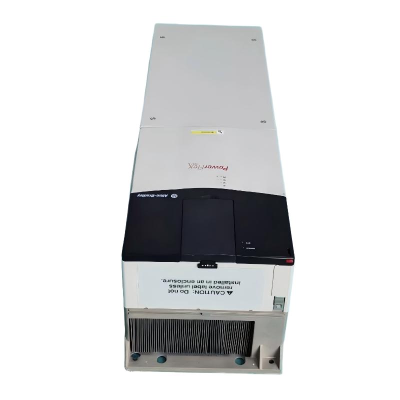
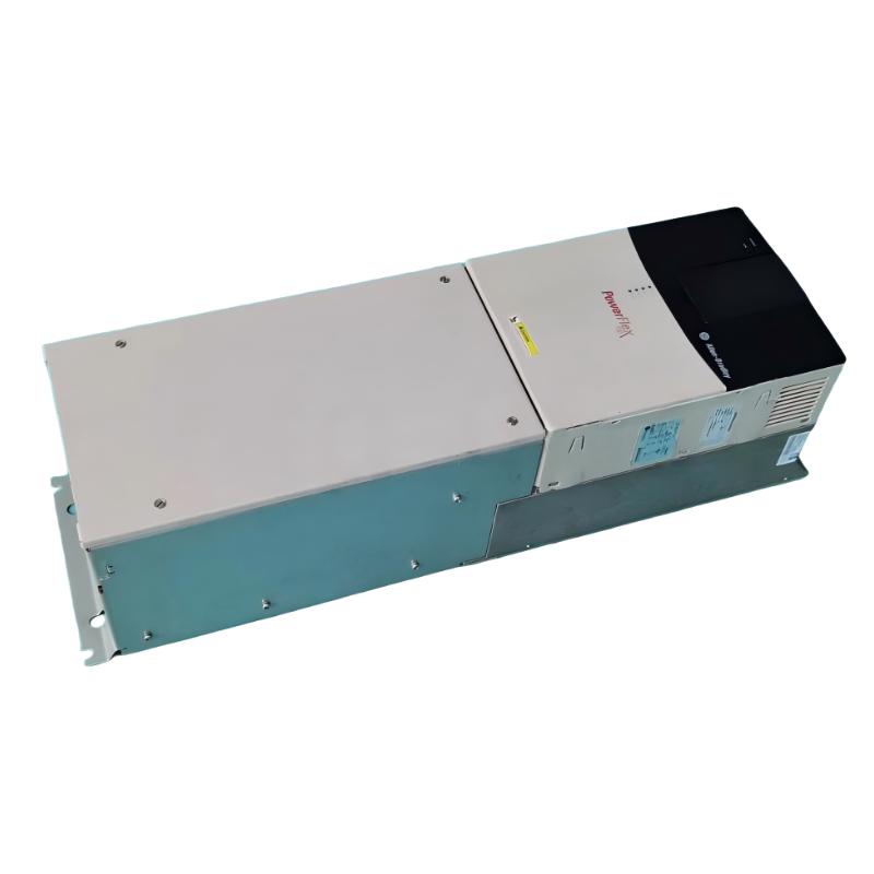
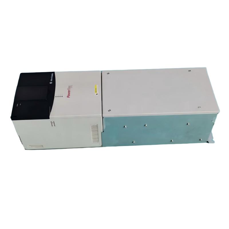
- Allen Bradley
- 20BC170A0ANNAND0
- PowerFlex AC Drive
- USA
- 689.6 × 308.9 × 275.4 mm
- 37.19kg
- Xiamen, China
- New & In Stock
- T/T, PayPal, Western Union
- 1 Year
- 1-3 Working Days
- DHL, UPS, TNT, FedEx and EMS.
- 24-Hour Service
- COO
- 4
Our advantage

Global Logistics
We have a 10-year logistics and express cooperation agreement, so our products can be shipped to any place in the world.

Brand new and original
Our products are imported in bulk from the place of origin. Because of the cooperative relationship, our products are all original and 100% new.

24-hour service
We provide 7*24 hours service to our customers. We will be there whenever you need us.

Price advantage
All our products are priced very favorably because we have our own warehouse and supply.
| Company Information | |||
| [email protected] | |||
| Mobile | +8615980777398 | ||
| +8615980777398 | |||
| 15980777398 |
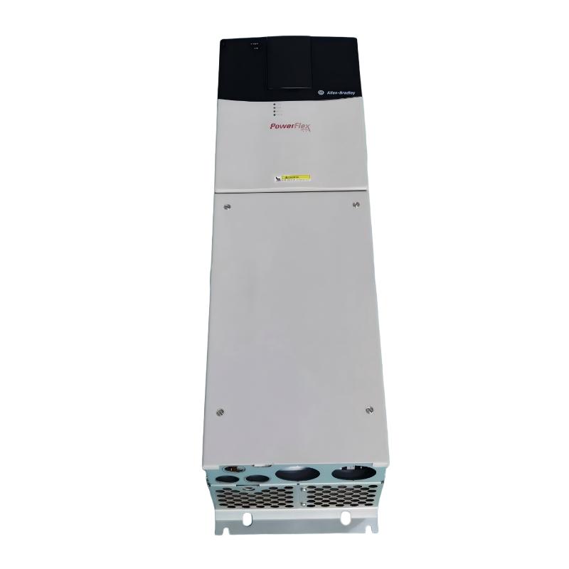
Allen-Bradley 20BC170A0ANNAND0 AC Drive — Technical Specifications, Applications, Advantages, and Related Models
1. Product Overview
The Allen-Bradley 20BC170A0ANNAND0 belongs to the PowerFlex 700 family of industrial variable-frequency AC drives. It is designed to regulate the speed and operation of compatible three-phase AC motors in industrial machinery, production equipment, and process-control systems.
The model is part of the 400 V-class drive range, with a rated output current of 170 A. The associated power ratings are approximately 90 kW for normal-duty operation and 75 kW for heavy-duty operation. This makes it relevant to larger motor-driven equipment where controlled acceleration, adjustable speed, and integration with industrial control circuits are required.
The 20BC170A0ANNAND0 is closely related to other 170 A PowerFlex 700 configurations. However, the complete catalog number matters: variations in the suffix can indicate differences in I/O, enclosure, braking hardware, feedback capability, or other options. Those differences should be checked before selecting a replacement.
|
Parameter |
Specification |
|---|---|
|
Model number |
20BC170A0ANNAND0 |
|
Brand |
Allen-Bradley |
|
Product series |
PowerFlex 700 |
|
Product family |
20B |
|
Product type |
Variable-frequency AC drive |
|
Input voltage class |
400 V AC |
|
Nominal supply voltage |
400 V AC |
|
Input supply |
Three-phase |
|
Motor output |
Three-phase AC |
|
Rated output current |
170 A |
|
Normal-duty power rating |
Approximately 90 kW |
|
Heavy-duty power rating |
Approximately 75 kW |
|
Control type |
Vector-control drive |
|
I/O configuration |
120 V I/O configuration indicated by the related catalog configuration |
|
Motor feedback |
No feedback option indicated |
|
Internal braking resistor |
Not included in the related base configuration |
|
Braking IGBT |
Not included in the related base configuration |
|
Enclosure |
Confirm against the exact catalog-number specification |
|
Human Interface Module (HIM) |
Confirm the supplied configuration |
|
Communication options |
Confirm installed hardware and supported adapters |
|
Product lifecycle |
Discontinued model; verify condition and availability before purchase |
Catalog-number note: The 20BC170A0ANNAND0 and 20BC170A0ANNANC0 share much of their model designation, but their suffixes are different. Do not assume that their control I/O, enclosure, or accessory configuration is identical. The exact nameplate and catalog documentation should take precedence over a family-level description.
2. Detailed Technical Specifications
2.1 Electrical Specifications
The drive is designed for three-phase industrial power systems in the 400 V class. Its 170 A output-current rating makes it suitable for larger motors and demanding industrial loads, provided the motor’s current requirements and overload characteristics remain within the drive’s specified limits.
The normal-duty and heavy-duty ratings should be treated separately. Normal-duty operation is generally associated with applications that have less demanding overload requirements, while heavy-duty operation is intended for applications that may require greater overload capability.
|
Parameter |
Specification |
|---|---|
|
Model number |
20BC170A0ANNAND0 |
|
Brand |
Allen-Bradley |
|
Series |
PowerFlex 700 |
|
Input voltage |
400 V AC nominal |
|
Drive voltage range |
380–480 V AC class |
|
Input phases |
3-phase |
|
Output phases |
3-phase |
|
Rated output current |
170 A |
|
Normal-duty power rating |
90 kW |
|
Heavy-duty power rating |
75 kW |
|
Nominal motor voltage |
400 V |
|
Nominal mains frequency |
50 Hz |
|
Maximum output frequency |
Up to 420 Hz, subject to drive configuration and operating limits |
|
Typical efficiency |
Approximately 97.5% at rated current and nominal line voltage |
|
Input frequency tolerance |
47 Hz listed as a specification value; confirm the complete allowable range in the technical manual |
|
Line-voltage tolerance |
Approximately ±10%, subject to the manufacturer’s stated operating conditions |
|
Braking IGBT |
Not included |
|
Internal braking resistor |
Not included |
|
Feedback option |
No feedback |
|
Control method |
Vector control with 120 V I/O |
2.2 Control and I/O Specifications
One of the most important features of this particular model is its 120 V I/O control configuration. This distinguishes it from related PowerFlex 700 variants that use 24 V I/O or other control arrangements.
A 120 V I/O configuration may be useful in existing industrial installations where control signals are based on 120 V circuits. However, the actual terminal arrangement, signal functions, and wiring requirements must be checked before connecting the drive to a PLC, relay panel, or machine controller.
|
Parameter |
Specification |
|---|---|
|
Model number |
20BC170A0ANNAND0 |
|
Control type |
Vector control |
|
Control I/O voltage class |
120 V |
|
Analogue inputs |
2 |
|
Analogue outputs |
2 |
|
Digital inputs |
6 |
|
Digital outputs |
3 |
|
Motor feedback |
No feedback option |
|
Human Interface Module |
Blank plate configuration; no HIM supplied |
|
Internal communication module |
Not included |
|
Braking IGBT |
Not included |
|
Internal braking resistor |
Not included |
|
EMC filter |
Second-environment filter configuration |
|
Conformal coating |
Included in the specified configuration |
|
Parameter configuration |
Required during commissioning |
|
External control integration |
Subject to terminal layout and installed options |
The absence of a separate communication module does not mean that every communication protocol is necessarily unavailable. The complete communication arrangement depends on supported adapters, installed hardware, and the control architecture. Verify the actual unit before designing a network connection.
2.3 Environmental and Protection Specifications
The 20BC170A0ANNAND0 is specified with IP20 / NEMA Type 1 protection. This makes it appropriate for a suitably protected indoor electrical installation, such as a control cabinet or industrial electrical room.
It is not intended to be exposed directly to rain, washdown, or uncontrolled quantities of conductive dust. If the installation environment is harsh, the cabinet and its ventilation system must provide the necessary additional protection.
|
Parameter |
Specification |
|---|---|
|
Model number |
20BC170A0ANNAND0 |
|
IP protection rating |
IP20 |
|
NEMA enclosure rating |
Type 1 |
|
Maximum altitude without derating |
1,000 m, subject to installation conditions |
|
Relative humidity |
5–95%, non-condensing |
|
Listed operating-temperature value |
50°C at 400 V AC; confirm the permitted ambient range and derating requirements |
|
Listed storage-temperature value |
−40°C minimum listed |
|
Shock rating |
15 G peak for 11 ms, as listed |
|
Vibration rating |
0.152 mm displacement, 1 G peak, as listed |
|
Cooling |
Adequate ventilation and manufacturer-specified clearances required |
|
Installation environment |
Suitable protected industrial location |
|
Corrosive atmosphere |
Avoid unless the installation provides appropriate protection |
Environmental limits must be considered together. High ambient temperature, restricted airflow, excessive altitude, and contamination can all affect the drive’s operating life and reliability.
2.4 Physical Dimensions and Weight
The dimensions and weight matter when replacing an existing drive, designing a control cabinet, or planning transport and installation.
For the standard Frame 6 configuration associated with this model family, the approximate dimensions below can be used for preliminary planning. The actual drive should be checked against its nameplate and the applicable dimensional drawing, particularly if it has a different junction-box or enclosure arrangement.
|
Parameter |
Specification |
|---|---|
|
Model number |
20BC170A0ANNAND0 |
|
Frame reference |
Frame 6 |
|
Approximate height |
850 mm |
|
Approximate width |
403.9 mm |
|
Approximate depth |
275.5 mm |
|
Approximate dimensions in metres |
0.850 × 0.404 × 0.276 m |
|
Approximate drive-only weight |
71.44 kg |
|
Approximate weight with packaging |
100.9 kg |
|
Weight unit |
kg |
|
Mounting arrangement |
Industrial mounting surface or suitable control-cabinet structure |
|
Installation clearance |
Follow the dimensional drawing and installation instructions |
|
Lifting arrangements |
Select lifting equipment based on the actual unit and its handling instructions |
Physical specification warning: The dimensions and weight are preliminary reference values for the associated frame configuration. Confirm that the particular 20BC170A0ANNAND0 unit matches the expected frame and mechanical arrangement before fabricating a cabinet, preparing mounting holes, or planning a direct replacement.
3. Product Introduction
The Allen-Bradley 20BC170A0ANNAND0 is an industrial variable-frequency AC drive intended to control the speed of compatible three-phase AC motors. It regulates motor operation by adjusting the output frequency and voltage, allowing machinery to operate at different speeds according to production requirements.
In a fixed-speed motor installation, the motor generally runs at a speed determined by the supply frequency and its operating characteristics. With a variable-frequency drive, the motor speed can be adjusted to suit changing process demands. This can provide better control over material flow, pumping capacity, ventilation, and the movement of industrial equipment.
The 20BC170A0ANNAND0 belongs to the PowerFlex 700 family and is designed for industrial applications requiring substantial motor current capacity. Its 170 A output rating and 90 kW normal-duty rating make it relevant to larger motors used in manufacturing and process industries.
The model uses vector control with 120 V I/O. This arrangement may be especially relevant when maintaining an existing machine whose control circuits were designed around 120 V signals. Keeping the same I/O arrangement can simplify some aspects of a replacement project, although wiring, terminals, parameters, and the condition of the existing control system must still be checked.
The drive is supplied without a braking IGBT and without an internal drive-mounted braking resistor. As a result, applications that require rapid stopping or frequent deceleration may need an external braking solution or a different drive configuration. The correct approach depends on the load inertia, stopping time, operating cycle, and energy generated during deceleration.
The unit also has no feedback option. Applications requiring encoder-based closed-loop speed regulation or position feedback therefore need additional engineering assessment before this model is selected.
The catalog configuration includes conformal coating and a second-environment EMC filter arrangement. These features can be useful in appropriate industrial installations, but they do not remove the need to assess cabinet design, electrical noise, grounding, ventilation, and environmental conditions.
4. Main Applications
4.1 Conveyor Systems and Material Handling
Conveyor systems often need to run at different speeds depending on the production rate, the amount of material being transported, and the operating sequence of the machine. A variable-frequency drive provides a means of controlling conveyor motor speed without relying solely on mechanical speed adjustment.
The 20BC170A0ANNAND0 may be suitable for compatible larger conveyor motors where the required current and duty fall within its ratings.
Typical applications include:
-
Industrial production-line conveyors.
-
Bulk-material transport systems.
-
Transfer conveyors.
-
Packaging and sorting machinery.
-
Material-feeding equipment.
-
Selected warehouse and manufacturing handling systems.
Controlled acceleration can reduce sudden mechanical loading on belts, couplings, gearboxes, and driven components. However, if the conveyor must stop quickly or repeatedly, the braking requirements should be assessed separately.
4.2 Pumping and Fluid-Handling Systems
Pumps are frequently used in applications where the required flow varies throughout the day or production cycle. A variable-frequency drive can adjust motor speed to match demand, provided the pump and process permit variable-speed operation.
Potential applications include:
-
Industrial water circulation.
-
Process-fluid transfer.
-
Cooling-water systems.
-
Water-treatment equipment.
-
General-purpose industrial pumping.
-
Selected fluid-distribution systems.
In suitable variable-torque applications, lowering pump speed can reduce energy consumption compared with operating continuously at full speed and restricting flow mechanically. Actual savings depend on the pump curve, system resistance, process demand, and operating hours.
4.3 Industrial Fans and Ventilation Equipment
Industrial fans are often required to provide different airflow rates under different operating conditions. Variable-speed control can help regulate ventilation, exhaust flow, and process-air movement.
Potential applications include:
-
Large industrial ventilation fans.
-
Process exhaust equipment.
-
Air-circulation systems.
-
Selected cooling fans.
-
Industrial air-handling equipment.
The drive must be matched to the fan motor and its operating profile. High-inertia fans may require carefully configured acceleration and deceleration ramps, and any regenerative or braking requirements should be reviewed before installation.
4.4 Processing and Production Machinery
Many industrial machines use AC motors to drive mechanical processes that must operate at adjustable speeds. A drive in this power class may be suitable when the motor’s current, power, and overload requirements fall within the specified limits.
Examples include:
-
Mixers and agitators.
-
Selected material-processing machines.
-
Industrial production equipment.
-
Auxiliary machinery in manufacturing plants.
-
Large motor-driven process systems.
For machines requiring precise positioning, encoder-based feedback, or servo-level motion control, a dedicated drive or different configuration may be more suitable.
4.5 Large Mechanical Drive Systems
The 170 A output-current rating allows the drive to be considered for larger motor-driven equipment. The suitability of the model depends on the motor’s rated current, starting requirements, load inertia, duty cycle, and operating environment.
Potential applications include compatible gear-driven machinery, larger mechanical transport equipment, and selected industrial process drives.
The power rating alone should not be used to confirm suitability. The drive must be checked against the actual motor nameplate and the worst-case operating conditions.
5. Main Advantages
5.1 High Output-Current Capacity
The 170 A output-current rating makes the drive relevant to a range of high-power industrial motor applications. This capacity can be useful for large equipment that would exceed the current rating of smaller general-purpose drives.
The distinction between the 90 kW normal-duty rating and the 75 kW heavy-duty rating also helps define its intended operating range. The correct rating must be selected according to the motor load and the required overload performance.
5.2 Vector-Control Capability
Vector control provides a motor-control approach designed to offer better control of motor torque and speed than basic frequency adjustment alone in suitable applications.
Actual performance depends on motor data, parameter settings, control mode, operating speed, and whether the application needs feedback. Since this model has no feedback option, it should not be assumed to provide encoder-based closed-loop performance.
5.3 Compatibility with 120 V Control Circuits
The 120 V I/O arrangement can be useful when the existing machine uses 120 V control signals. This may reduce the need to redesign the entire control interface when maintaining compatible equipment.
However, compatibility should never be inferred from the voltage label alone. Terminal functions, electrical ratings, signal isolation, and the existing control architecture must be confirmed before wiring.
5.4 Adjustable Speed and Controlled Acceleration
Adjustable motor speed can help machinery operate according to actual process requirements. Properly configured acceleration and deceleration ramps can also reduce abrupt changes in mechanical loading.
This can be particularly useful for conveyors, pumps, fans, and other equipment where sudden speed changes may affect the process or increase wear on mechanical components.
5.5 Potential Energy Efficiency Improvements
In applications where motor speed can be reduced without compromising the process, variable-speed control may lower energy consumption. This is often relevant to pumps and fans, where the required output can vary substantially.
The drive’s listed efficiency is approximately 97.5% at rated current and nominal line voltage. Overall system efficiency will also depend on the motor, driven equipment, operating speed, power quality, and load profile.
5.6 Industrial EMC and Coating Features
The specified configuration includes a second-environment EMC filter arrangement and conformal coating. These features are relevant when evaluating the drive for an industrial electrical installation.
They do not eliminate the need for proper cable routing, grounding, shielding, cabinet design, and protection against unsuitable environmental conditions. The complete installation must meet the requirements of the machine and the surrounding electrical system.
5.7 Useful for Existing PowerFlex 700 Installations
For a machine already designed around the PowerFlex 700 family, a compatible drive of the same configuration may reduce the amount of redesign required.
The 120 V I/O arrangement is particularly important to verify because other models in the same family may use different control I/O. Braking hardware, feedback, communications, enclosure, and firmware also need to be checked.
5.8 A Basis for Replacement Planning
Because this is a discontinued model, documenting its technical characteristics can help maintenance teams prepare for a future replacement. A planned replacement is usually easier to engineer than an emergency substitution after equipment failure.
The assessment should include the motor, load, control wiring, network requirements, cabinet dimensions, braking needs, and commissioning procedure.
6. Five Related PowerFlex 700 Models
The following models are from the same drive family or are closely related to the target model. They offer useful comparison points, but differences in the catalog suffix can affect the control interface and installation requirements.
|
Model |
Series |
Electrical Parameters |
Control / Configuration |
Dimensions (H × W × D) |
Weight (kg) |
|---|---|---|---|---|---|
|
20BC170A0ANNAND0 |
PowerFlex 700 |
400 V class; 170 A; 90 kW normal duty / 75 kW heavy duty |
Vector control; 120 V I/O; no feedback; no internal braking resistor |
Approx. 850 × 403.9 × 275.5 mm; verify frame drawing |
Approx. 71.44 |
|
20BC170A0ANNANA0 |
PowerFlex 700 |
400 V class; 170 A; 90 kW normal duty / 75 kW heavy duty |
Standard control with 24 V I/O; no feedback; no internal braking resistor |
Verify exact drawing for the selected frame |
Verify exact unit |
|
20BC170A0ANNANN0 |
PowerFlex 700 |
400 V class; 170 A; 90 kW normal duty / 75 kW heavy duty |
Standard control configuration; no feedback; no internal braking resistor |
Verify exact drawing for the selected frame |
Verify exact unit |
|
20BC170A0AYNANA0 |
PowerFlex 700 |
400 V class; 170 A; 90 kW normal duty / 75 kW heavy duty |
Related 170 A configuration; check exact enclosure and option suffix |
Standalone IP54 / NEMA Type 12 version listed at approx. 1,828.8 × 711.3 × 487.8 mm |
Approx. 229.07, including packaging |
|
20BC140A0ANNANA0 |
PowerFlex 700 |
400 V class; 140 A; approximately 75 kW normal duty / 55 kW heavy duty |
Lower-current option; verify I/O and braking configuration |
Approx. 644.5 × 308.9 × 275.4 mm; verify actual configuration |
Approx. 37.19 |
Comparison and Selection Guidance
– 20BC170A0ANNAND0: The reference model for installations requiring a 170 A drive with 120 V I/O.
– 20BC170A0ANNANA0: A related 170 A model with a 24 V I/O arrangement. It may be relevant when the control system uses 24 V signals, but it is not automatically a direct substitute for the 120 V I/O version.
– 20BC170A0ANNANN0: Another related 170 A PowerFlex 700 configuration. Check its exact control and option details against the existing drive.
– 20BC170A0AYNANA0: A related configuration worth considering when the enclosure arrangement differs. Its standalone enclosure dimensions and packaged weight should not be treated as equivalent to the standard frame configuration.
– 20BC140A0ANNANA0: A lower-current alternative that may suit a smaller motor, provided its current and overload ratings meet the application requirements.
Dimensions and weights marked for verification should be confirmed using the exact mechanical drawing before cabinet fabrication or equipment replacement.
7. Five Popular Models from the Same Brand
The following models represent other commonly used industrial drive families. They cover different power ranges and control requirements, so they should be considered as potential alternatives only after the application has been evaluated.
|
Model |
Series |
Electrical Parameters |
Typical Applications |
Dimensions (H × W × D) |
Weight (kg) |
|---|---|---|---|---|---|
|
25B-D017N104 |
PowerFlex 525 |
480 V-class family; 17 A output-current class; confirm exact power rating for voltage and duty |
Compact conveyors, pumps, fans, general machinery |
Verify exact frame drawing |
Verify exact unit |
|
25B-D024N104 |
PowerFlex 525 |
480 V-class family; 24 A output-current class; confirm exact power rating for voltage and duty |
Packaging equipment, material handling, industrial machinery |
Verify exact frame drawing |
Verify exact unit |
|
22B-D017N104 |
PowerFlex 40 |
480 V-class family; 17 A output-current class; verify exact catalog specifications |
General-purpose variable-speed control and compact equipment |
Verify exact frame drawing |
Verify exact unit |
|
20F11NC015JA0NNNNN |
PowerFlex 753 |
PowerFlex 753 family; confirm exact voltage, current, and power rating |
Process equipment and larger industrial machinery |
Verify exact frame and enclosure drawing |
Verify exact unit |
|
20G11NC022JA0NNNNN |
PowerFlex 755 |
PowerFlex 755 family; confirm exact voltage, current, and power rating |
Industrial process control and applications needing configurable control options |
Verify exact frame and enclosure drawing |
Verify exact unit |
Product Family Comparison
PowerFlex 525
The PowerFlex 525 is generally used for compact and general-purpose industrial motor-control applications. It can be appropriate for smaller motors, but its current capacity is substantially different from that of the 170 A PowerFlex 700.
PowerFlex 40
The PowerFlex 40 family is intended for general-purpose variable-speed applications. It may be suitable for smaller machinery, but its control functions and power rating must be compared with the actual process requirements.
PowerFlex 753
The PowerFlex 753 family is relevant to industrial applications that require configurable drive options. It may be worth assessing during a replacement or upgrade project, but the exact voltage class, output current, control hardware, and enclosure must be confirmed.
PowerFlex 755
The PowerFlex 755 family is designed for more advanced industrial motor-control applications. It may offer a route for an engineered upgrade where the existing PowerFlex 700 is no longer available, but it should not be treated as a plug-in replacement without a compatibility review.
The dimensions and weights in this comparison are intentionally marked for verification where the exact configuration has not been confirmed. A model name or current rating alone is not sufficient to establish the correct physical measurements.
8. Installation and Replacement Considerations
Before installing or replacing the 20BC170A0ANNAND0, check the following points.
1. Motor nameplate: Confirm the motor’s rated voltage, current, power, frequency, and connection arrangement.
2. Duty classification: Ensure the selected normal-duty or heavy-duty rating matches the real load and overload requirements.
3. Control voltage: Check whether the existing system uses 120 V I/O. Do not assume that a 24 V I/O variant will connect directly to the same control circuit.
4. Braking requirements: This model does not include a braking IGBT or internal braking resistor. Confirm whether external braking equipment is needed.
5. Feedback requirements: The drive has no feedback option. Applications requiring encoder feedback should be assessed separately.
6. Communication requirements: Confirm the network interface, supported adapter, and installed communication hardware before integration with a PLC or supervisory system.
7. Cooling and enclosure: Ensure that the electrical cabinet provides sufficient ventilation and the required environmental protection.
8. Mechanical compatibility: Verify the exact frame, dimensions, mounting holes, terminal arrangement, and clearance requirements.
9. Condition of used equipment: For used or refurbished units, inspect the cooling system, capacitors, terminals, control boards, and available fault history.
10. Commissioning: Set up the motor data, command source, acceleration and deceleration ramps, protection settings, and control parameters before returning the machine to service.
11. Lifecycle planning: Since the model is discontinued, compare the cost and risk of repair with the engineering effort involved in upgrading to another drive.
9. Final Summary
The Allen-Bradley 20BC170A0ANNAND0 is a 400 V-class PowerFlex 700 variable-frequency AC drive with a 170 A output-current rating, a 90 kW normal-duty rating, and a 75 kW heavy-duty rating. Its defining configuration feature is vector control with 120 V I/O, making that control-voltage arrangement an important consideration for existing installations.
The drive can be suitable for compatible conveyor systems, pumps, fans, processing equipment, and other industrial machinery that requires adjustable motor speed and substantial current capacity. Its main benefits include high-current operation, vector-control capability, adjustable acceleration, and the potential to improve process control and energy use in appropriate applications.
The principal limitations are the absence of an internal braking resistor, the absence of a braking IGBT, the lack of a feedback option, and the need to verify communications and enclosure details. These points should be evaluated before selecting a replacement or designing a new installation.
For a like-for-like replacement, begin with the complete catalog number and the actual nameplate. If an exact match is unavailable, compare related PowerFlex 700 models first, paying particular attention to the I/O voltage, braking configuration, feedback, communications, and mechanical dimensions.
Because the model is discontinued, a planned replacement strategy is advisable. The best alternative is not necessarily the model with the closest power rating; it is the one that meets the motor’s electrical requirements, matches the control system, fits the installation, and provides the functions needed by the machine.