

ProductPRODUCT
Featured products
Contact Us
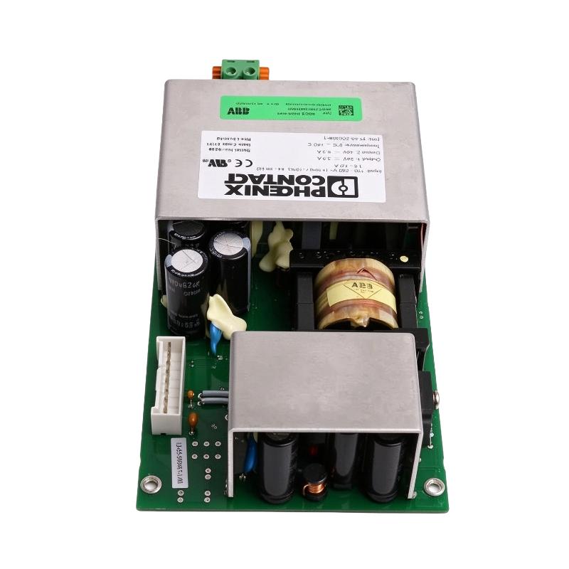
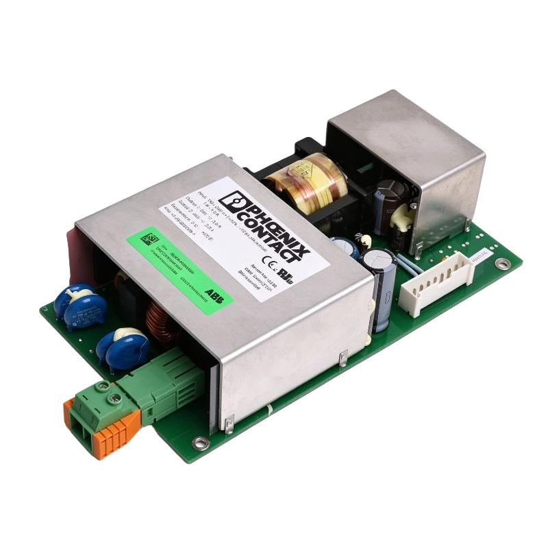
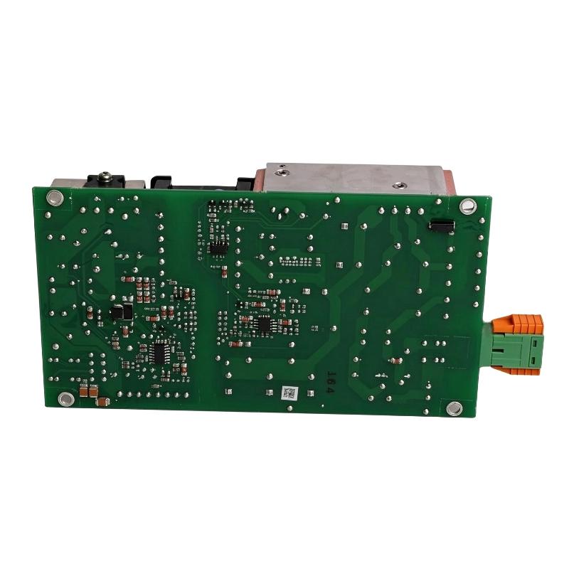
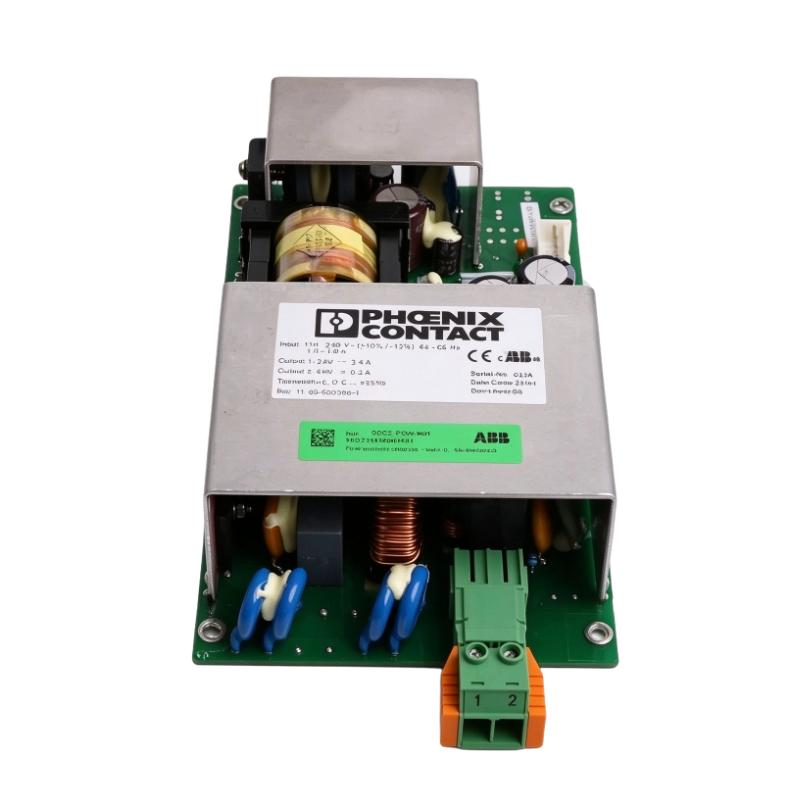
- ABB
- SDCS-POW-H01 3ADT318700R1501
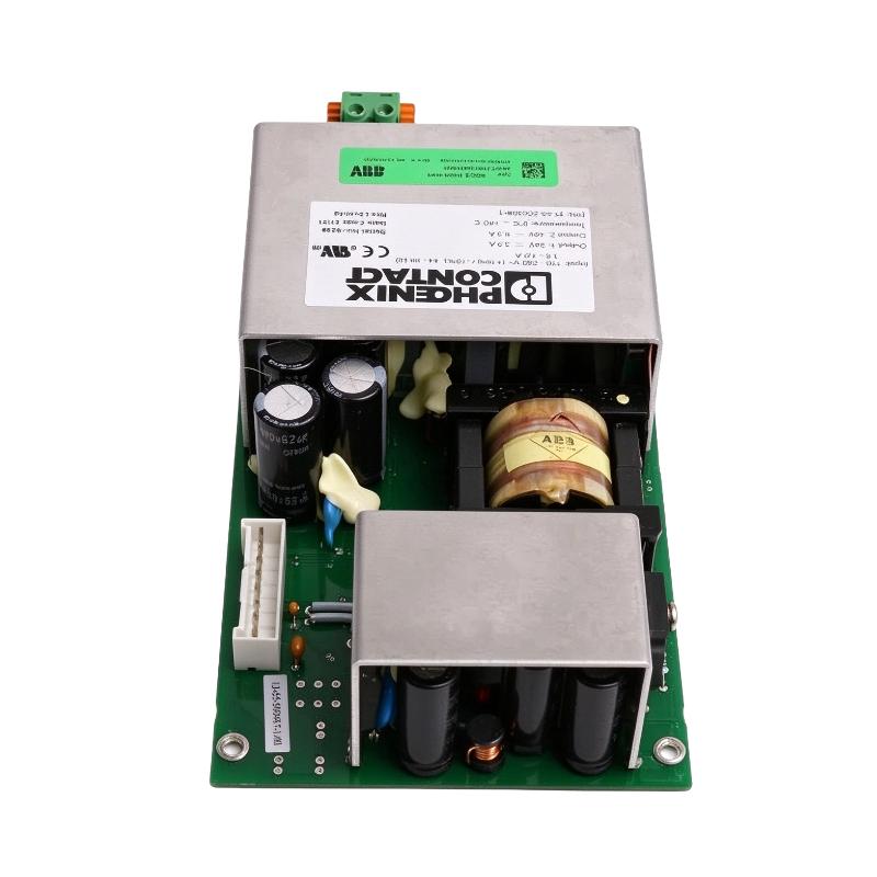
- DCS800 Power Supply Board
- Sweden (SE)
- 155 × 45 × 120 mm
- 0.45 kg
- Xiamen, China
- New & In Stock
- T/T, PayPal, Western Union
- 1 Year
- 1-3 Working Days
- DHL, UPS, TNT, FedEx and EMS.
- 24-Hour Service
- COO
- 7
Our advantage

Global Logistics
We have a 10-year logistics and express cooperation agreement, so our products can be shipped to any place in the world.

Brand new and original
Our products are imported in bulk from the place of origin. Because of the cooperative relationship, our products are all original and 100% new.

24-hour service
We provide 7*24 hours service to our customers. We will be there whenever you need us.

Price advantage
All our products are priced very favorably because we have our own warehouse and supply.
| Company Information | |||
| [email protected] | |||
| Mobile | +8615980777398 | ||
| +8615980777398 | |||
| 15980777398 |
Product Overview
The ABB SDCS-POW-H01, identified by ordering number 3ADT318700R1501, is a power supply board used to generate auxiliary DC voltages for electronic control assemblies. In an industrial DC drive, the control electronics need their own power supply to operate independently of the motor’s main power circuit. This board supports that requirement by supplying the internal electronic circuits and associated control boards.
The SDCS-POW-H01 is associated with ABB DCS800 drive equipment. Its function is different from that of the armature converter or field exciter: rather than converting the main motor power or regulating field current, it supplies the auxiliary power required by the drive’s electronics. A fault in this supply can affect control-board operation and may prevent the drive from starting or maintaining normal control.
The board accepts an auxiliary supply through its designated input connection. Depending on the applicable hardware configuration, the input can be 115 V AC, 230 V AC, or 230 V DC. The board generates the DC rails required by the associated electronics, including a 24 V DC output and a 48 V DC output. The specific supply arrangement must be checked against the board version and the equipment documentation. <Cite refs={[“turn321048search18″,”turn321048search1”]}/>
When replacing the SDCS-POW-H01, engineers should verify the full ordering number, input supply arrangement, board connections, and associated control hardware. The same board designation may appear in different drive-system contexts, so the actual application and hardware configuration should be confirmed before installation.
Technical Specifications
| Parameter | Specification |
|---|---|
| Manufacturer | ABB |
| Model | SDCS-POW-H01 |
| Ordering Number | 3ADT318700R1501 |
| Product Type | DCS800 Power Supply Board |
| Product Family | ABB DCS800 |
| Auxiliary Input Voltage | 115 V AC / 230 V AC / 230 V DC, according to configuration |
| AC Input Frequency | 45–65 Hz |
| Nominal Output Power | 96 W |
| DC Output Rails | 24 V DC and 48 V DC |
| Auxiliary Supply Connection | XAUX (X99) |
| Dimensions | 155 × 45 × 120 mm |
| Weight | 0.45 kg |
Product Features
- Auxiliary power generation: Supplies the DC voltages required by the drive’s electronic control assemblies.
- Multiple input configurations: Supports specified AC and DC auxiliary supply arrangements, depending on the hardware configuration.
- 24 V DC and 48 V DC outputs: Provides power rails for compatible electronic circuits.
- Dedicated auxiliary input: Uses the designated XAUX connection for the external supply.
- Control-system support: Supplies associated control boards rather than directly powering the motor.
- Drive-specific integration: Fits into the relevant electronic assembly when the board version and connections match the installed system.
- Maintenance identification: The SDCS-POW-H01 model and 3ADT318700R1501 ordering number help identify the required replacement board.
Working Principle
The SDCS-POW-H01 receives auxiliary electrical power and converts it into the regulated DC voltages needed by the drive’s electronic circuits. The input supply is connected through the designated auxiliary input, and the board’s power conversion circuitry generates the required output rails for the control electronics.
The basic power path is:
Auxiliary AC or DC Supply → SDCS-POW-H01 → DC Supply Rails → Drive Control Electronics
For the documented DCT880 T6 standard and T8 configuration, the board’s auxiliary input supports 115 V AC, 230 V AC, or 230 V DC. The published technical data specifies a nominal output power of 96 W, corresponding to 3.5 A at 24 V DC and 0.25 A at 48 V DC. These values relate to that documented hardware configuration and should not automatically be applied to every installation carrying the same board designation. <Cite refs={[“turn321048search18”]}/>
The control boards depend on these auxiliary voltages to execute their electronic functions. If the power supply board fails, the associated control electronics may lose power even when the drive’s main incoming supply remains available. This can lead to a loss of control-board indications, communication, or drive readiness.
When troubleshooting a suspected power supply fault, engineers should check the auxiliary input, protective fuse, board connections, and output rails according to the applicable service procedure. A missing output voltage does not necessarily mean the board itself has failed; an input problem or short circuit in a connected load may produce similar symptoms.
Role in the DCS800 Drive Control Architecture
The SDCS-POW-H01 occupies the auxiliary power-supply stage of the drive’s electronic architecture. It supplies the control electronics, while the main converter and field-excitation components perform the power conversion functions associated with motor operation.
| System Element | Function |
|---|---|
| Auxiliary AC/DC Supply | Provides input power to the power supply board |
| SDCS-POW-H01 | Generates the DC supply rails for associated electronics |
| Drive Control Board | Executes control functions and coordinates drive operation |
| Armature Converter | Controls the main DC motor armature circuit |
| Field Exciter | Supplies controlled excitation current where required |
| Internal Electronic Boards | Use the auxiliary DC rails for their operating power |
| Protective Fuse | Protects the auxiliary input circuit according to the applicable design |
| Drive Monitoring System | Reports relevant control and power-supply status where supported |
A power supply board fault can affect several electronic functions at once. Troubleshooting should therefore include the auxiliary input, output rails, connected loads, and relevant control-board connections before the board is replaced.
Industrial Applications
| Application | Practical Use |
|---|---|
| ABB DCS800 DC Drives | Supplying auxiliary power to compatible drive electronics |
| Industrial DC Motor Control | Powering electronic circuits that coordinate motor operation |
| Rolling and Processing Equipment | Supporting control electronics in applicable DC drive installations |
| Material Handling Machinery | Maintaining auxiliary power for drive-control functions |
| Industrial Production Lines | Supporting the electronic control section of compatible motor drives |
| Drive Cabinet Maintenance | Replacing a defective auxiliary power board after electrical checks |
| Preventive Maintenance | Checking auxiliary input, output rails, fuses, and board connections |
| Drive Refurbishment | Restoring the auxiliary supply stage when the exact board configuration has been verified |
Installation and Maintenance
- Verify the complete ordering number: Confirm SDCS-POW-H01 and 3ADT318700R1501 against the installed board and equipment documentation.
- Isolate the auxiliary supply: Disconnect the applicable AC or DC input and follow the approved electrical isolation procedure. Verify that hazardous voltage is absent before handling the board.
- Confirm the input configuration: Check whether the installation uses 115 V AC, 230 V AC, or 230 V DC. Do not apply an input voltage based solely on the board model name.
- Inspect the auxiliary input connection: Check the XAUX connection and associated wiring for loose terminals, damaged insulation, or signs of overheating.
- Check the input protection: Inspect the applicable fuse and input circuit. Replace a failed fuse only after investigating the reason it operated.
- Inspect the board and connectors: Look for damaged components, contamination, corrosion, or loose connectors. Check that the board is correctly seated in its designated position.
- Verify output wiring: Inspect the connected DC supply rails and associated electronic loads for short circuits or wiring errors before applying power.
- Check connected control boards: Confirm that the receiving electronics are compatible with the board’s output configuration and that no downstream fault is overloading the supply.
- Measure the output rails: Use the approved procedure to check the required DC outputs. Compare the readings with the specifications for the exact installed configuration.
- Investigate repeated supply failures: If the fuse operates again or an output collapses under load, check the input source, connected loads, wiring, and board condition rather than repeatedly replacing the fuse.
- Test the drive electronics: After the auxiliary supply has been verified, check that the associated control boards power up and that the drive reports the expected status.
- Record maintenance results: Document the board ordering number, input voltage, output measurements, fuse condition, and commissioning observations for future troubleshooting.
Compatible System Components
| Component | Function |
|---|---|
| ABB DCS800 Control Electronics | Use the auxiliary DC supply generated by the board |
| Drive Control Board | Executes the drive’s control functions |
| Internal Electronic Boards | Receive the required auxiliary power rails |
| Auxiliary AC/DC Supply | Provides input power to the SDCS-POW-H01 |
| Input Fuse | Protects the auxiliary supply circuit |
| XAUX Input Connector | Connects the external auxiliary supply |
| Internal DC Supply Wiring | Distributes the generated voltages to connected electronics |
| Electronic Board Connectors | Carry power to the associated control hardware |
Recommended Related Models
| Model | Product Type | Selection Consideration |
|---|---|---|
| ABB SDCS-POW-H01 / 3ADT318700R1501 | DCS800 Power Supply Board | Reference model for the specified auxiliary power-supply application |
| ABB SDCS-POW-1C | Power Supply Board | Verify the exact hardware version and electrical characteristics before considering substitution |
| ABB SDCS-CON-4 | DCS800 Control Board | Related drive control hardware; not a direct replacement for a power supply board |
| ABB SDCS-CON-2 | Control Board | Compare the installed drive generation and control-board configuration |
| ABB SDCS-FEX-4 | Field Exciter Control Board | Relevant to compatible field-excitation arrangements |
| ABB SDCS-PIN-4 | Power Interface Board | Related power-conversion hardware with a different function |
| ABB SDCS-COM-8 | Communication Board | Used for supported communication functions in applicable drive configurations |
| ABB DCS800 | DC Drive Product Family | Main drive family for checking associated electronic hardware |
| ABB DCS880 | DC Drive Product Family | Related DC drive family; verify board compatibility separately |
| ABB Advant OCS | Industrial Control System Family | Broader control-system context for compatible hardware configurations |
Key Advantages
- Auxiliary DC power generation for compatible drive electronics.
- Multiple specified input supply options, depending on configuration.
- Dedicated supply rails for associated electronic boards.
- Clear model and ordering-number identification for maintenance.
- Integration with compatible industrial DC drive hardware.
Technical FAQs
Which input voltage should be applied to the SDCS-POW-H01?
The documented configuration supports 115 V AC, 230 V AC, or 230 V DC. The correct input depends on the installed hardware arrangement and applicable wiring documentation. Confirm the connection and input rating before energizing the board.
What does the SDCS-POW-H01 power inside the drive?
It generates auxiliary DC voltages for the associated electronic control boards. It does not directly supply the motor’s main armature power or replace the drive’s field exciter.
Why might the control electronics remain inactive even when the drive’s main supply is available?
The auxiliary input may be missing, the input fuse may have operated, a board connection may be loose, or a downstream electronic load may be affecting the DC outputs. Check the auxiliary supply path and output rails before concluding that the board has failed.
Can the SDCS-POW-H01 be replaced by another ABB power supply board?
Not on brand or general function alone. The replacement must match the required input configuration, output rails, connector arrangement, mounting interface, and drive hardware version.