

ProductPRODUCT
Featured products
Contact Us
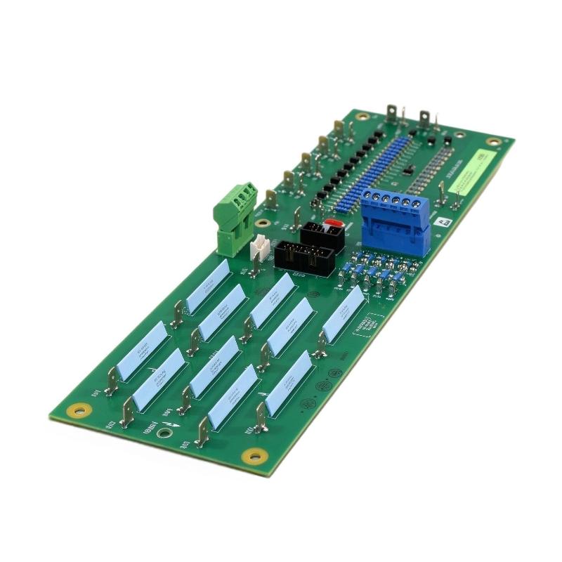
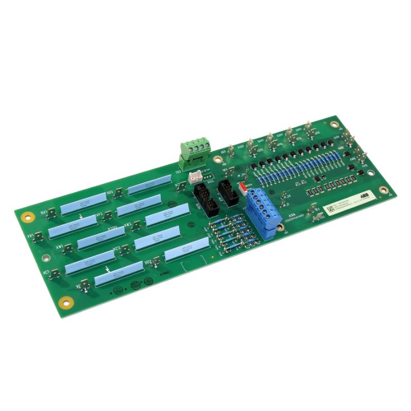
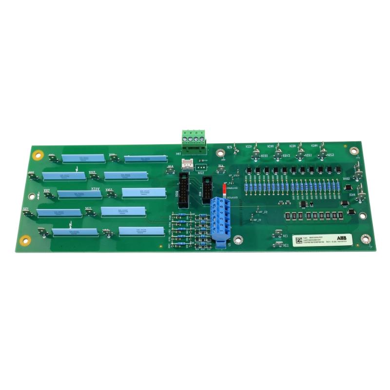
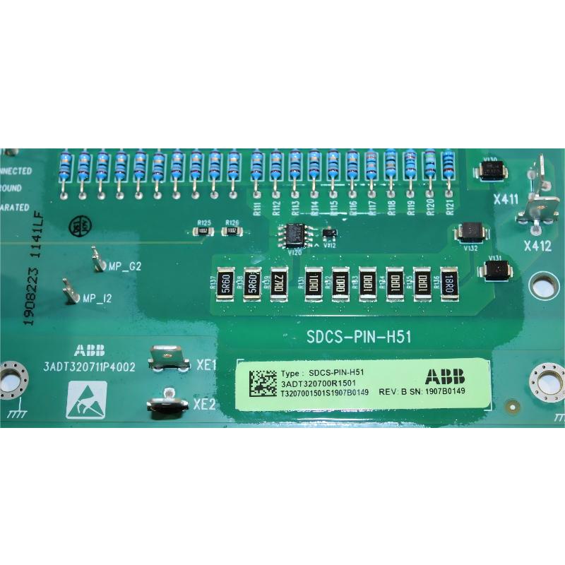
- ABB
- SDCS-PIN-H51 3ADT320700R1501
- Measurement Board
- Sweden (SE)
- 165 × 25 × 130 mm
- 0.5 kg
- Xiamen, China
- New & In Stock
- T/T, PayPal, Western Union
- 1 Year
- 1-3 Working Days
- DHL, UPS, TNT, FedEx and EMS.
- 24-Hour Service
- COO
- 4
Our advantage

Global Logistics
We have a 10-year logistics and express cooperation agreement, so our products can be shipped to any place in the world.

Brand new and original
Our products are imported in bulk from the place of origin. Because of the cooperative relationship, our products are all original and 100% new.

24-hour service
We provide 7*24 hours service to our customers. We will be there whenever you need us.

Price advantage
All our products are priced very favorably because we have our own warehouse and supply.
| Company Information | |||
| [email protected] | |||
| Mobile | +8615980777398 | ||
| +8615980777398 | |||
| 15980777398 |
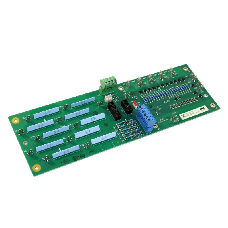
Product Overview
The ABB SDCS-PIN-H51, ordering number 3ADT320700R1501, is a measurement board used in ABB DCS880 high-power DC drive converters. It receives electrical feedback from the converter’s power circuit, including current-transformer signals, AC and DC voltage measurements, and temperature-sensor input. These signals allow the drive control system to evaluate actual operating conditions during motor operation. <Cite refs={[“turn149562search12″,”turn149562search14”]}/>
In a large DC drive installation, the controller needs accurate feedback from the power stage to coordinate converter operation and monitor electrical conditions. The SDCS-PIN-H51 handles this measurement function rather than supplying the motor’s main power or independently controlling the drive. For example, in a high-power industrial drive, current feedback helps the controller determine whether the converter’s electrical response corresponds to its configured operating conditions.
The board is used with DCS880 converter frame sizes H6, H7, and H8. Its interface depends on the frame: H6 connects to the SDCS-CON-H01 control board, while H7 and H8 use the SDCS-OPL-H01 optical power-link board. The current-measurement configuration also differs by converter rating, with current-transformer ratios and firmware type-code settings determining the appropriate scaling. <Cite refs={[“turn149562search12″,”turn149562search17”]}/>
When replacing this board, matching the complete model and ordering number is only the first step. The converter frame, current-transformer ratio, voltage-input arrangement, temperature-sensor connection, and control interface must also correspond to the installed system. Incorrect measurement scaling can produce inaccurate feedback even when the replacement board is electrically connected.
Technical Specifications
| Parameter | Specification |
|---|---|
| Manufacturer | ABB |
| Model | SDCS-PIN-H51 |
| Ordering Number | 3ADT320700R1501 |
| Product Type | DCS880 Measurement Board |
| Product Family | ABB DCS880 |
| Compatible Converter Frames | H6, H7, H8 |
| Current Measurement | Four current-transformer input channels |
| Voltage Measurement | AC and DC voltage measurement inputs |
| Temperature Input | DCS880 temperature-sensor input |
| Current Transformer Ratios | 1:2500 or 1:4000, according to converter configuration |
| Control Connection | XC12 |
| Dimensions | 165 × 25 × 130 mm |
| Weight | 0.5 kg |
Product Features
- Four current-measurement channels: Accepts current-transformer signals through designated input pairs for monitoring the converter’s AC-side current.
- AC and DC voltage measurement: Supports multiple input arrangements for measuring supply and motor voltages across different voltage ranges.
- Temperature-sensor input: Provides a connection for the DCS880 temperature-sensing circuit.
- Configurable current scaling: Supports current-transformer ratios of 1:2500 or 1:4000, depending on the converter frame and rating.
- H6–H8 converter integration: Fits the measurement architecture used in the corresponding DCS880 high-power converter frames.
- Dedicated control interface: Connects to the SDCS-CON-H01 or SDCS-OPL-H01 according to the converter frame.
- Firmware-based configuration: Uses converter type-code settings to establish the appropriate current-measurement scaling.
- Power-stage feedback: Supplies measured electrical information for use by the drive control and monitoring functions.
Working Principle
The SDCS-PIN-H51 collects signals from the converter’s electrical measurement points and prepares them for the control system. It does not carry the main motor current through the board itself. Instead, current transformers provide measurement signals, while designated high-resistance input circuits measure voltage.
For current measurement, four channels connect to current transformers through the X231/X232, X241/X242, X251/X252, and X261/X262 terminal pairs. The AC signals are rectified on the board. The associated burden-resistor scaling is configured through the converter’s firmware type code for the applicable 1:2500 or 1:4000 current-transformer ratio. <Cite refs={[“turn149562search12″,”turn149562search17”]}/>
Voltage measurement uses different terminals depending on the voltage range. The board supports a low-voltage measurement arrangement through X15, direct high-resistance measurement inputs for specified AC voltage ranges, and an isolated measurement arrangement using additional components where required. These connections must be configured for the actual supply and motor voltage rather than selected by appearance alone.
The temperature-sensor connection at X22 provides the interface for the DCS880 temperature measurement. Together, the current, voltage, and temperature signals give the control system information about the converter’s operating condition.
A simplified signal path is:
Power Circuit → Current Transformers and Voltage Inputs → SDCS-PIN-H51 → Drive Control Electronics
The controller interprets the resulting signals using the configured current scaling, voltage settings, and drive parameters. If those settings do not match the installed converter, measured values can be incorrect even when the board itself is functioning normally.
Role in the DCS880 Control Architecture
The SDCS-PIN-H51 forms part of the measurement path between the power circuit and the drive control electronics. Its job is to supply electrical feedback, while the associated control and interface boards manage communication with the converter’s control architecture.
| System Element | Function |
|---|---|
| AC Supply | Provides input power to the converter |
| Converter Power Stage | Performs the main electrical power-conversion function |
| Current Transformers | Supply current signals to the measurement board |
| SDCS-PIN-H51 | Handles current and voltage measurement signals and temperature-sensor input |
| SDCS-CON-H01 | Provides the control interface in the H6 arrangement |
| SDCS-OPL-H01 | Provides the optical power-link interface in H7 and H8 arrangements |
| Temperature Sensor | Supplies thermal measurement information |
| Drive Control Software | Interprets measurement signals according to configured settings |
| Protection and Monitoring Functions | Evaluate operating conditions and respond to relevant faults |
Industrial Applications
| Application | Practical Use |
|---|---|
| ABB DCS880 H6 Converters | Providing current, voltage, and temperature measurement feedback |
| ABB DCS880 H7 Converters | Supporting power-stage measurement in the corresponding converter arrangement |
| ABB DCS880 H8 Converters | Supplying measurement signals for high-current converter configurations |
| Industrial DC Motor Drives | Supporting feedback-based control of the converter power stage |
| Metal Processing Equipment | Providing electrical measurement data for compatible DC drive systems |
| Rolling Mill Drives | Supporting current and voltage monitoring in high-power drive installations |
| Heavy Industrial Machinery | Feeding power-stage measurements to the drive control system |
| Converter Maintenance | Replacing a measurement board after verifying the installed configuration |
| Drive Commissioning | Checking measurement scaling and input configuration |
| Preventive Maintenance | Inspecting connectors, measurement wiring, and sensor feedback |
Installation and Maintenance
- Verify the complete board reference: Confirm SDCS-PIN-H51 and ordering number 3ADT320700R1501 against the installed board and converter documentation.
- Identify the converter frame: Establish whether the installation uses H6, H7, or H8 hardware. Check the associated control or optical power-link interface before removing the board.
- Isolate the converter: Follow the approved shutdown, isolation, and discharge procedure. Verify the absence of hazardous voltage before working on the measurement circuit.
- Record the existing configuration: Note the converter’s rated current, current-transformer ratio, voltage class, terminal connections, and relevant type-code settings before replacement.
- Inspect current-transformer wiring: Check all four measurement channels for loose connections, damaged insulation, incorrect wiring, or signs of overheating.
- Verify current scaling: Confirm that the configured transformer ratio and current settings correspond to the converter nameplate. Do not copy settings from another frame or current rating without checking compatibility.
- Check voltage-measurement connections: Verify the selected terminals against the actual supply and motor voltage range. Inspect any additional components required for isolated voltage measurement.
- Inspect the temperature-sensor circuit: Check the X22 connection and sensor wiring for open circuits, short circuits, or implausible readings.
- Examine board connectors: Inspect XC12 and other relevant connections for damage, contamination, or poor contact. Confirm the correct interface for the installed converter frame.
- Check mounting and insulation: Ensure that the board is secured correctly and that grounding, insulation, and cable routing comply with the converter’s installation requirements.
- Validate measurement readings: Follow the approved commissioning procedure to compare reported current, voltage, and temperature values with expected operating conditions or suitable independent measurements.
- Document the final configuration: Record the replacement board number, converter frame, current-transformer ratio, voltage-input arrangement, and commissioning results for future troubleshooting.
Compatible System Components
| Component | Function |
|---|---|
| ABB SDCS-CON-H01 | Control board used in the applicable DCS880 H6 arrangement |
| ABB SDCS-OPL-H01 | Optical power-link board used in the applicable H7 and H8 arrangements |
| Current Transformers | Provide current signals to the measurement channels |
| DCS880 Temperature Sensor | Supplies temperature feedback through the X22 connection |
| Power-Stage Voltage Connections | Supply AC and DC voltage-measurement signals |
| Voltage Isolation Components | Support specified isolated voltage-measurement arrangements |
| Measurement Wiring and Connectors | Carry signals between the power stage and the measurement board |
| DCS880 Converter Power Stage | Provides the electrical quantities monitored by the board |
Recommended Related Models
| Model | Product Type | Selection Consideration |
|---|---|---|
| ABB SDCS-PIN-H51 / 3ADT320700R1501 | DCS880 Measurement Board | Reference model for H6–H8 converter measurement arrangements |
| ABB SDCS-PIN-H41 | DCS880 Firing Pulse Transformer Board | Related power-stage interface board with a different function |
| ABB SDCS-CON-H01 | DCS880 Control Board | Relevant to the H6 control arrangement; not a direct replacement for the measurement board |
| ABB SDCS-OPL-H01 | DCS880 Optical Power-Link Board | Relevant to the H7 and H8 interface arrangement |
| ABB SDCS-POW-H01 / 3ADT318700R1501 | DCS880 Power Supply Board | Supplies auxiliary power to associated electronic assemblies |
| ABB SDCS-FEX-4 | Field Exciter Control Board | Related hardware for applicable field-excitation arrangements |
| ABB DCS880 H6 | DC Converter | Converter frame using the SDCS-PIN-H51 measurement arrangement |
| ABB DCS880 H7 | DC Converter | Converter frame with its corresponding control and power-unit configuration |
| ABB DCS880 H8 | DC Converter | High-current converter frame requiring configuration-specific measurement settings |
| ABB DCS800 | DC Drive Product Family | Related DC drive family; board compatibility must be verified independently |
| ABB DCS880 Rebuild Kit | Converter Rebuild Components | Relevant when rebuilding or servicing the associated power-stage assembly |
Key Advantages
- Four current-transformer measurement channels.
- Dedicated AC and DC voltage-measurement inputs.
- Temperature-sensor interface for converter monitoring.
- Configurable current scaling for supported converter ratings.
- Integration with DCS880 H6, H7, and H8 converter architectures.
Technical FAQs
Which signals can the SDCS-PIN-H51 process?
The board supports current-transformer signals, AC and DC voltage measurements, and temperature-sensor input. The specific terminals used depend on the voltage range and converter configuration.
Why must the current-transformer ratio match the converter settings?
The current-transformer ratio determines the relationship between the actual power-circuit current and the signal measured by the board. Incorrect scaling can cause the drive to interpret current incorrectly, affecting monitoring and control.
Is the SDCS-PIN-H51 compatible with every DCS880 frame?
It is specified for H6, H7, and H8 converter arrangements. The control interface, current-transformer ratio, voltage inputs, and configuration settings must match the particular converter.
What should be checked if current readings are incorrect after board replacement?
Check the current-transformer wiring, transformer ratio, firmware type-code settings, voltage-input configuration, board connections, and temperature-sensor circuit. Validate the readings using the approved commissioning procedure before changing drive-control parameters.