

ProductPRODUCT
Featured products
Contact Us
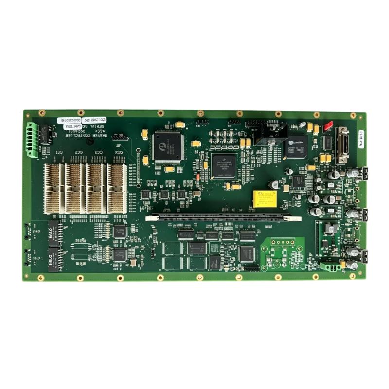
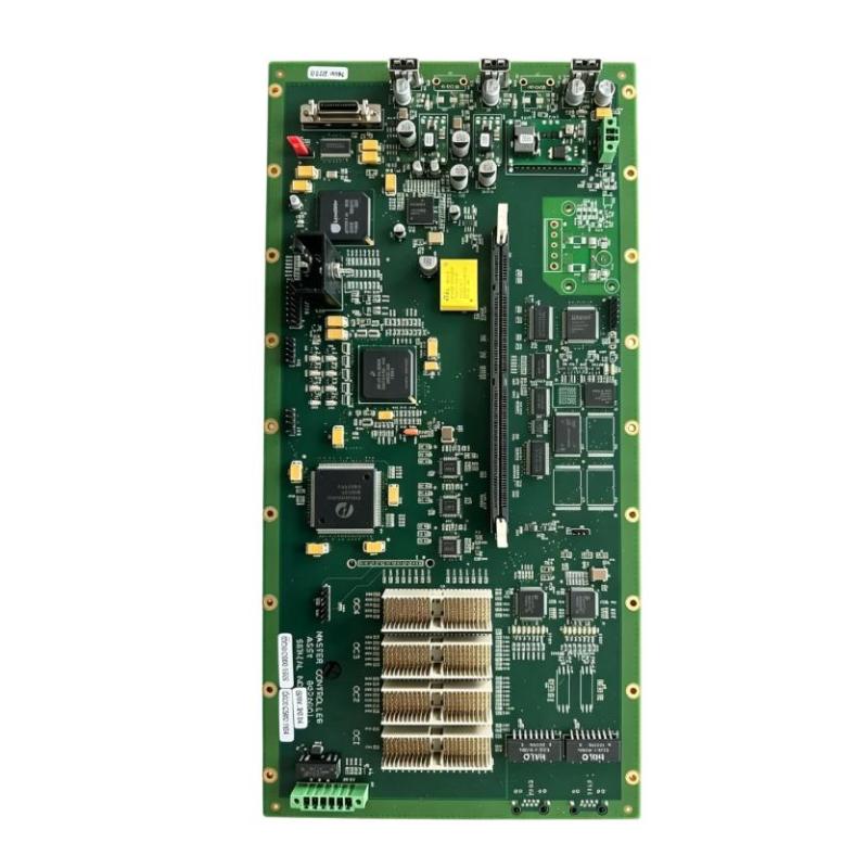
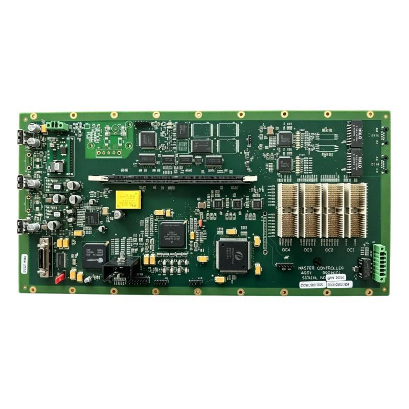
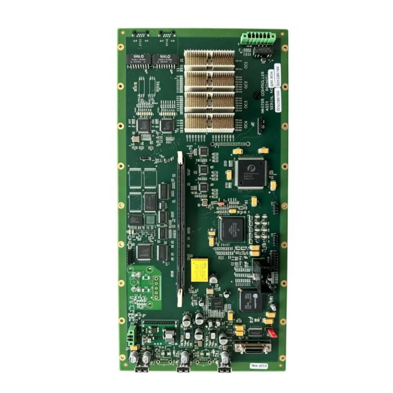
- ABB
- 852A045-1
- DTC Standard Model PCB Assembly
- Sweden (SE)
- 230 × 30 × 120 mm
- 1.02 kg
- Xiamen, China
- New & In Stock
- T/T, PayPal, Western Union
- 1 Year
- 1-3 Working Days
- DHL, UPS, TNT, FedEx and EMS.
- 24-Hour Service
- COO
- 18
Our advantage

Global Logistics
We have a 10-year logistics and express cooperation agreement, so our products can be shipped to any place in the world.

Brand new and original
Our products are imported in bulk from the place of origin. Because of the cooperative relationship, our products are all original and 100% new.

24-hour service
We provide 7*24 hours service to our customers. We will be there whenever you need us.

Price advantage
All our products are priced very favorably because we have our own warehouse and supply.
| Company Information | |||
| [email protected] | |||
| Mobile | +8615980777398 | ||
| +8615980777398 | |||
| 15980777398 |
Product Overview
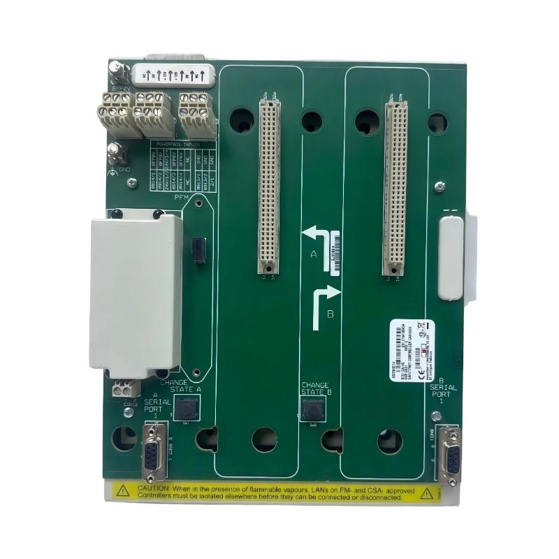
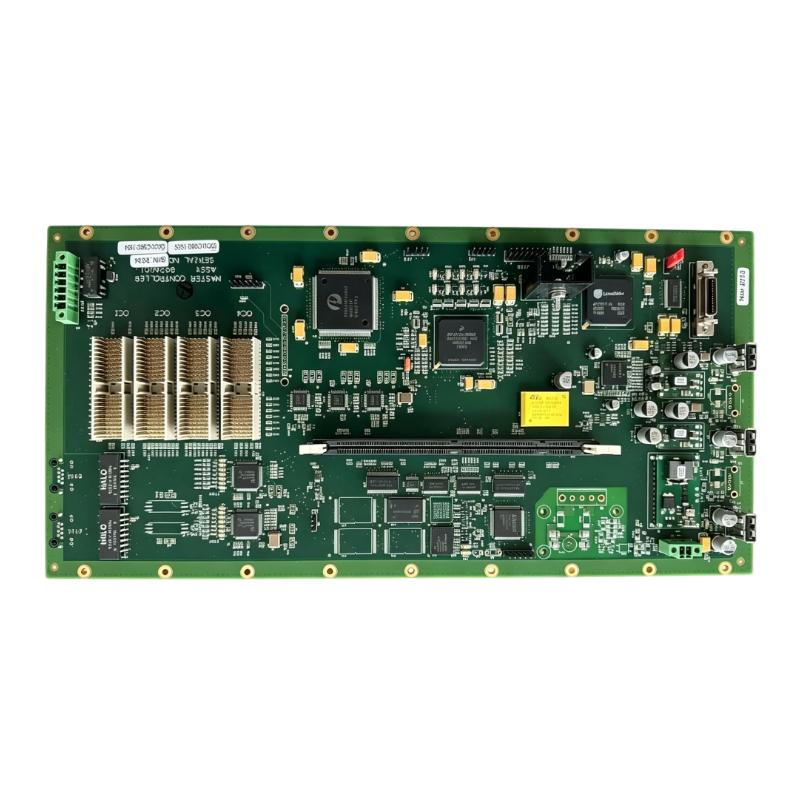
The ABB 852A045-1 PGC5000 DTC Standard Model PCB Assembly is a board-level component used within the PGC5000 control platform. The DTC Standard Model PCB forms part of the electronic hardware architecture responsible for handling the functions associated with the DTC section of the system.
In a PGC5000 installation, this type of PCB works together with controller, carrier, power, interface, and communication hardware rather than operating as an independent PLC. Its position at the board level makes it particularly relevant when maintaining existing PGC5000 equipment and replacing a specific electronic assembly.
For troubleshooting, the 852A045-1 should be evaluated together with the surrounding PGC5000 hardware. Symptoms such as loss of controller functionality, abnormal signals, or failure during initialization can involve the PCB itself, its connectors, power supply, carrier interfaces, or another connected assembly.
Technical Specifications
| Parameter | Specification |
|---|---|
| Product | ABB 852A045-1 PGC5000 DTC Standard Model PCB Assembly |
| Product Family | PGC5000 |
| Product Type | DTC Standard Model PCB Assembly |
| System Role | DTC-related controller electronics |
| Main Function | Electronic processing and system interface functions |
| Application | Industrial control and automation systems |
| Board Type | Printed Circuit Board Assembly |
| Dimensions | 230 × 30 × 120 mm |
| Weight | 1.02 kg |
Product Features
- DTC Standard Model PCB Assembly for the PGC5000 control platform.
- Board-level construction for integration within the PGC5000 electronic architecture.
- Works with associated controller, carrier, power, and interface hardware.
- Suitable for maintenance and replacement of compatible PGC5000 electronic assemblies.
- Supports continued operation of installed control equipment when the affected board requires replacement.
- Allows technicians to isolate board-level faults from problems in external system components.
Working Principle
The 852A045-1 operates as part of the PGC5000 electronic control architecture. Its circuitry processes or interfaces with the signals and data associated with the DTC section of the system, while the surrounding PGC5000 hardware supplies power and provides connections to other controller functions.
During normal operation, signals pass through the relevant board interfaces and are handled by the electronic circuitry on the PCB. The exact system-level function depends on how the board is integrated into the particular PGC5000 configuration.
This makes system-level troubleshooting important. A problem observed at the DTC or controller level does not automatically mean that the PCB itself is defective. Technicians should first verify power, connectors, carrier interfaces, communication paths, and associated assemblies before replacing the 852A045-1.
Role in a PGC5000 Control Architecture
| System Element | Function |
|---|---|
| 852A045-1 DTC Standard Model PCB | Provides DTC-related electronic processing and interface functions |
| PGC5000 SBC Controller PCB | Provides controller-level computing and control functions |
| PGC5000 SBC Carrier PCB | Provides mechanical support and electrical interconnection |
| Power Supply Section | Delivers operating power to the control electronics |
| I/O and Interface Hardware | Connects controller electronics with process signals and external devices |
| Communication Interfaces | Supports data exchange with other control-system equipment |
| Engineering or Service Equipment | Supports configuration, diagnostics, and maintenance |
| Field Devices | Provide process signals and receive control commands |
The 852A045-1 belongs to the board-level electronic layer of the PGC5000 architecture. Its operation depends on correct power, physical connections, and interaction with the other assemblies installed in the control system.
Industrial Applications
| Application | Typical Use |
|---|---|
| Industrial Control Systems | DTC-related electronic functions within PGC5000-based equipment |
| Process Control | Board-level control electronics in installed process-control systems |
| Production Equipment | Maintaining electronic assemblies used in automated production machinery |
| Legacy Automation Systems | Replacement of compatible PGC5000 PCB assemblies during equipment service |
| Control Panel Assemblies | Integration of controller electronics within industrial control cabinets |
| Industrial Equipment Maintenance | Board-level troubleshooting and replacement of affected control hardware |
Installation and Maintenance
- Verify the complete part number before installation and confirm that the 852A045-1 matches the existing PGC5000 hardware configuration.
- Disconnect system power and follow the established electrical isolation procedure before removing the PCB assembly.
- Record connector and cable positions before removal to prevent incorrect reconnection during installation.
- Inspect mating connectors for contamination, oxidation, bent contacts, or mechanical damage before fitting the replacement board.
- Use appropriate electrostatic-discharge precautions when handling the exposed PCB assembly.
- Check the mounting arrangement and make sure the board is properly seated without mechanical stress or excessive pressure.
- Verify power paths if the DTC section or associated controller electronics fail to initialize after installation.
- Inspect signal and communication connections when the board is installed but connected system functions remain unavailable.
- Check the PCB for visible damage such as overheated areas, cracked components, damaged connectors, or other physical abnormalities.
- Do not modify board-level circuitry unnecessarily unless the applicable equipment maintenance procedure specifically requires it.
- Verify the complete hardware configuration after installation and confirm that the related PGC5000 assemblies are correctly connected.
- Perform a controlled functional test after replacement, including power-up, controller initialization, communication checks, and relevant system operation tests.
Related Components
| Component | Function |
|---|---|
| PGC5000 SBC Controller PCB | Provides controller-level computing and control processing |
| PGC5000 SBC Carrier PCB | Provides mechanical support and electrical interconnection |
| PGC5000 Power Components | Supply operating power to controller and electronic assemblies |
| PGC5000 I/O Hardware | Interfaces control electronics with field devices |
| Communication Interfaces | Exchange data between controller hardware and external equipment |
| PCB Connectors | Establish electrical connections between related board assemblies |
| Control Cabinet Hardware | Provides the physical installation environment for the control electronics |
| Field Devices | Supply process signals and receive control outputs |
Recommended Related Models
| Model / Product Family | Product Type | Typical Application |
|---|---|---|
| ABB 852A045-1 | PGC5000 DTC Standard Model PCB Assembly | DTC-related control electronics |
| ABB 852A059-1 | PGC5000 SBC Controller PCB Assembly | Controller processing and computing |
| ABB 852A060-1B | PGC5000 SBC Carrier PCB Assembly | SBC mounting and electrical interconnection |
| ABB PGC5000 SBC Components | Single-Board Computer Components | Computing and controller functions |
| ABB PGC5000 I/O Components | I/O Hardware | Field signal acquisition and control outputs |
| ABB PGC5000 Communication Components | Communication Hardware | Data exchange within the control architecture |
| ABB PGC5000 Power Components | Power Hardware | Power supply and distribution for control electronics |
Key Advantages
- Provides DTC-related electronic functions within the PGC5000 platform.
- Board-level construction supports targeted equipment maintenance.
- Integrates with the surrounding PGC5000 controller architecture.
- Suitable for replacement of compatible electronic assemblies.
- Helps maintain existing PGC5000 control hardware without replacing unrelated system components.
Technical FAQs
What is the ABB 852A045-1 used for?
The 852A045-1 is a PGC5000 DTC Standard Model PCB Assembly. It forms part of the DTC-related electronic hardware within a compatible PGC5000 control architecture.
Is the 852A045-1 a standalone PLC controller?
No. It is a board-level PCB assembly within the PGC5000 system. Its functions depend on its integration with the associated controller, carrier, power, interface, and other system hardware.
What should be checked if the DTC-related functions become abnormal?
Check the PCB’s power supply, connectors, carrier or interface connections, associated controller hardware, and communication paths. Visible PCB damage should also be inspected before determining whether the 852A045-1 itself requires replacement.
What precautions are important when replacing the 852A045-1?
System power should be isolated before removal, connector positions should be documented, and appropriate ESD precautions should be used when handling the PCB. After installation, verify the connections and perform controlled system tests before returning the equipment to service.