

ProductPRODUCT
Featured products
Contact Us
- Schneider
- LC1F400M7
- Contactor
- France
- 206 x 213 x 219 mm
- 9.1 kg
- Xiamen, China
- New & In Stock
- T/T, PayPal, Western Union
- 1 Year
- 1-3 Working Days
- DHL, UPS, TNT, FedEx and EMS.
- 24-Hour Service
- COO
- 7
Our advantage

Global Logistics
We have a 10-year logistics and express cooperation agreement, so our products can be shipped to any place in the world.

Brand new and original
Our products are imported in bulk from the place of origin. Because of the cooperative relationship, our products are all original and 100% new.

24-hour service
We provide 7*24 hours service to our customers. We will be there whenever you need us.

Price advantage
All our products are priced very favorably because we have our own warehouse and supply.
| Company Information | |||
| [email protected] | |||
| Mobile | +8615980777398 | ||
| +8615980777398 | |||
| 15980777398 |
Product Overview
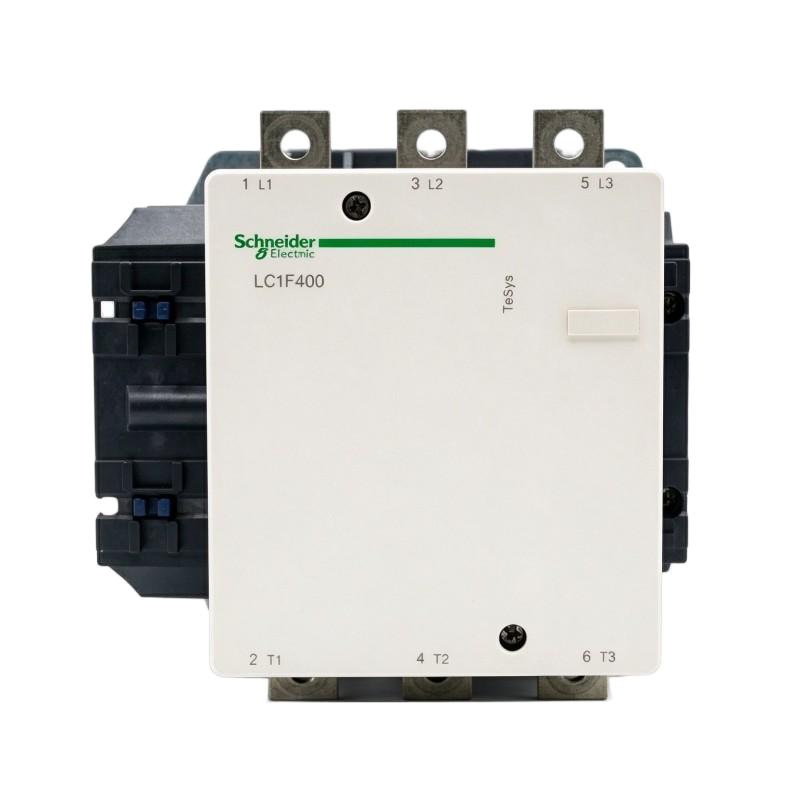
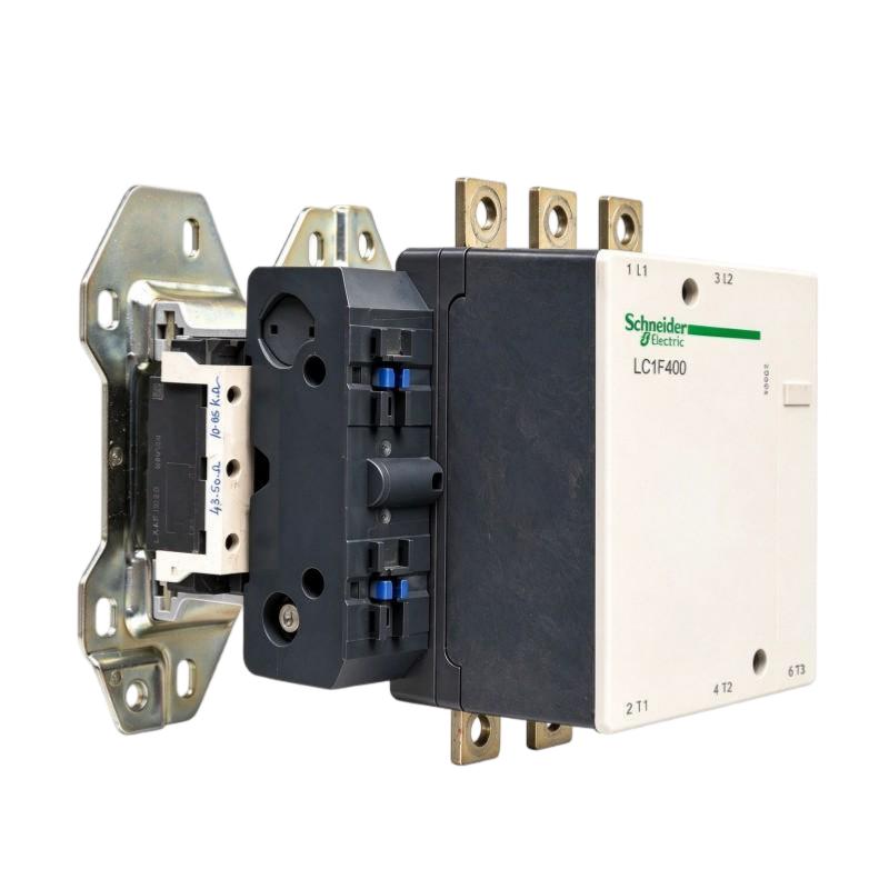
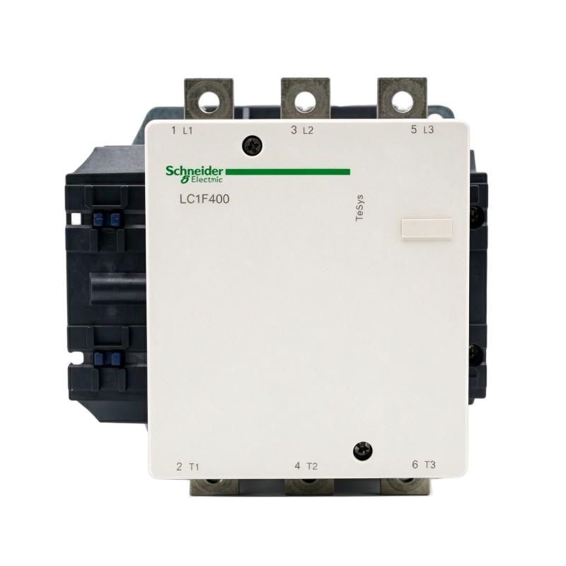
The Schneider Electric LC1F400M7 TeSys F Contactor is a heavy-duty three-pole power contactor designed for switching high-current electrical loads in industrial power distribution and motor-control systems. It belongs to the TeSys F product family and is intended for applications that require reliable electrical switching, motor starting, and control of large industrial loads.
A contactor is an electrically operated switching device. It uses an electromagnetic coil to open or close its main contacts, allowing a control circuit to operate a higher-power circuit. This arrangement enables industrial control systems to start and stop motors and other electrical equipment without requiring operators or PLC output devices to switch the main load directly.
The LC1F400M7 features three normally open main poles and a 220 V AC control coil. Its AC-3 rated operational current is 400 A at operating voltages up to 440 V AC. It also has a conventional free-air thermal current rating of 500 A under the specified 40°C conditions for AC-1 applications.
The distinction between AC-1 and AC-3 ratings is important. AC-1 applies to resistive or slightly inductive loads, while AC-3 is associated with starting squirrel-cage motors and switching them off during normal operation. The correct rating must therefore be selected according to the actual load category and operating conditions.
The LC1F400M7 is suitable for integration into industrial motor starters, electrical control panels, power distribution assemblies, and other systems requiring high-current switching. Its large contact structure and electromagnetic operating mechanism make it appropriate for installations where switching capacity and electrical reliability are important.
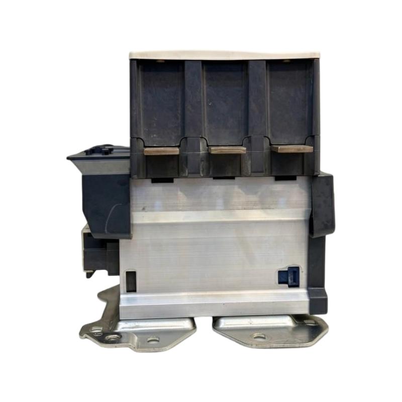
The model has a documented net weight of 9.1 kg and dimensions of 206 × 213 × 219 mm. These physical characteristics should be considered when planning panel installation, mounting arrangements, wiring access, and maintenance clearance.
Technical Specifications
| Parameter | Specification |
|---|---|
| Brand | Schneider Electric |
| Product Series | TeSys F |
| Model | LC1F400M7 |
| Product Type | Power Contactor |
| Contactor Application | Motor Control / Resistive Load Switching |
| Number of Poles | 3P |
| Main Contact Configuration | 3 Normally Open (3NO) |
| AC-3 Rated Operational Current | 400 A |
| AC-3 Operating Voltage | Up to 440 V AC |
| AC-1 Conventional Free-Air Thermal Current | 500 A at 40°C |
| Control Coil Voltage | 220 V AC |
| Control Circuit Frequency | 40–400 Hz |
| Rated Insulation Voltage | 1000 V |
| Rated Impulse Withstand Voltage | 8 kV |
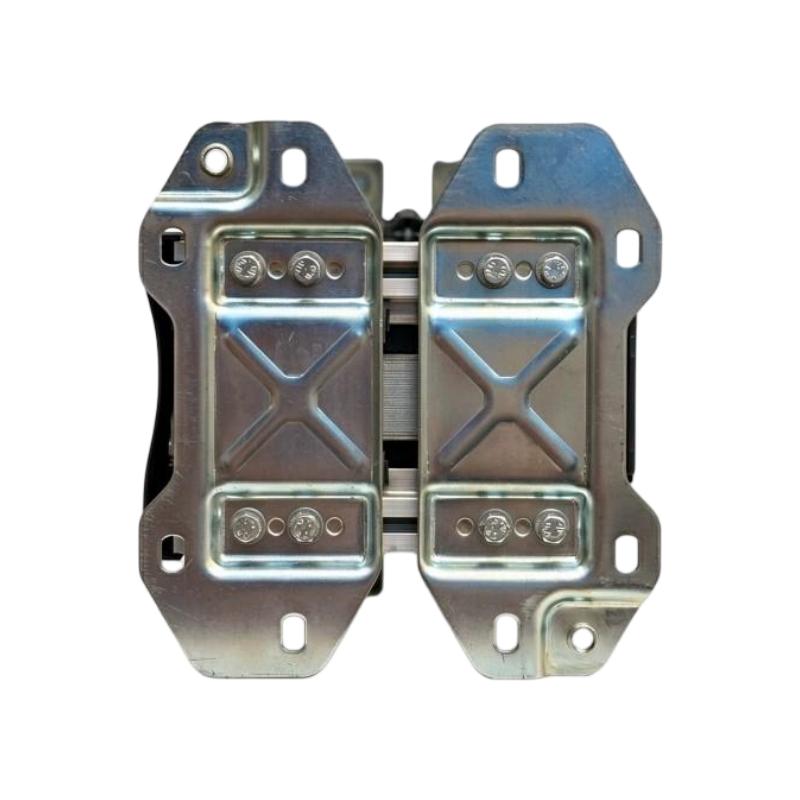
| Mounting | Panel / Plate Mounting |
| Front Protection | IP20 with appropriate terminal shrouds |
| Operating Temperature | -5°C to +55°C |
| Maximum Operating Altitude | 3000 m without temperature derating |
| Mechanical Durability | 10 million operating cycles |
| Dimensions | 206 × 213 × 219 mm |
| Weight | 9.1 kg |
| Product Lifecycle | Discontinued |
Note: Electrical ratings depend on the utilization category, operating voltage, ambient temperature, and installation conditions. Always consult the applicable manufacturer documentation when selecting protection devices and designing a motor starter.
Function and Working Principle
The LC1F400M7 operates through an electromagnetic mechanism that controls the opening and closing of its three main power contacts. Its basic function is to allow a relatively low-power control signal to operate a high-current electrical circuit.
1. Electromagnetic Coil Operation
The contactor contains a 220 V AC control coil. When the rated control voltage is applied, current flows through the coil and creates a magnetic field.
This magnetic field attracts the movable armature toward the fixed magnetic assembly. The mechanical movement operates the main contact system and closes the three normally open power poles.
When the control voltage is removed, the magnetic field collapses and the return mechanism moves the armature back to its original position. The main contacts open, interrupting the controlled circuit.
This electromagnetic operating principle allows a PLC, relay, push-button station, or other control device to command a high-current load through an appropriate control circuit.
2. Three-Pole Main Contact Switching
The LC1F400M7 has three normally open main contacts. These contacts are designed for switching the three phases of a compatible three-phase electrical circuit.
When the contactor is energized, all three main poles close to establish the electrical connection. When the coil is de-energized, the poles open and disconnect the controlled load.
For three-phase motor applications, this arrangement allows the contactor to control the motor’s incoming power supply. Correct phase wiring and upstream protection are essential for safe operation.
3. Motor Starting and Stopping
The contactor can be incorporated into a direct-on-line motor starter. In this arrangement, the contactor connects the motor directly to the electrical supply when a start command is received.
When the stop command is issued, the coil is de-energized and the main contacts open.
A complete motor starter normally includes additional components such as short-circuit protection, overload protection, control devices, and an appropriate disconnecting arrangement. The contactor itself is not a substitute for these protective devices.
4. Load Switching and Electrical Performance
The LC1F400M7 is designed for high-current switching applications. Its AC-3 rating of 400 A is particularly relevant when selecting it for compatible motor-control duties.
The AC-1 thermal current rating of 500 A applies to a different load category and must not be used as the motor-switching rating.
Engineers should evaluate the load type, starting current, switching frequency, operating voltage, and expected service conditions before selecting the contactor.
5. Control Circuit and Main Power Circuit Separation
The control coil and main contacts perform different functions. The coil receives the control signal, while the main contacts switch the power circuit.
This separation makes it possible to incorporate the contactor into PLC-based automation systems. The PLC can issue a control command through a suitable relay or output interface, while the contactor handles the main electrical load.
The control circuit must be designed for the 220 V AC coil specification. A 24 V DC PLC output should not be connected directly to this coil without an appropriately rated interface.
Role in Industrial Control Systems
The LC1F400M7 can serve as a main switching component in industrial motor-control and electrical distribution systems. It is commonly incorporated into a broader electrical assembly that includes protective devices, control relays, PLCs, and operator interfaces.
PLC-Based Motor Control
A programmable logic controller can manage the operating sequence of industrial machinery. It may receive signals from sensors, process conditions, and operator commands before issuing a motor start or stop request.
The PLC output can operate an appropriately rated interface relay, which then controls the 220 V AC contactor coil.
This arrangement allows automated systems to coordinate large motor loads with other production equipment. The PLC manages the control logic, while the contactor performs the power-switching function.
Motor Starter Assemblies
The contactor can be used in motor starter panels where a high-current switching device is required.
A typical motor starter assembly may contain:
- Main circuit breaker or fused disconnect.
- LC1F400M7 contactor.
- Motor overload protection.
- Control transformer or control power supply, where required.
- PLC or relay-based control circuit.
- Operator push buttons and status indicators.
- Terminal blocks and grounding components.
The final design depends on motor characteristics, protection coordination, and the applicable electrical standards.
Electrical Distribution Systems
In industrial power distribution assemblies, contactors can be used to control selected loads according to operating schedules or automation commands.
For example, a production facility may use contactors to switch large auxiliary equipment or coordinate the operation of several electrical systems.
The LC1F400M7 should only be used within the electrical ratings and switching categories specified for the application.
HMI and Operator Control
An HMI can provide operators with start, stop, and operating-status functions. The HMI typically communicates with a PLC, which processes the commands and controls the contactor through the appropriate electrical interface.
Interlocks and safety logic should be designed independently according to the machine’s risk assessment. A standard contactor should not be treated as a complete safety-rated isolation or emergency-stop solution.
Industrial Applications
The LC1F400M7 is designed for high-current industrial switching. Its 400 A AC-3 rating makes it relevant to appropriately sized motor-control systems and other applications that fall within its specified electrical limits.
1. Large Industrial Motor Control
Industrial motors are used in compressors, pumps, fans, conveyors, and production machinery. A contactor provides an electrically operated method for connecting and disconnecting the motor supply.
In a suitable direct-on-line starter, the LC1F400M7 can be used to switch a compatible three-phase motor.
The motor’s rated current, starting conditions, utilization category, and switching frequency must be considered before selecting the contactor.
2. Pumping Stations
Industrial pumping stations often contain motors that operate according to pressure, flow, or tank-level requirements.
A PLC or pressure-control system can issue a start command to the contactor when the process requires pump operation. When the required condition is reached, the control system can remove the coil command and stop the motor.
For pump installations, appropriate overload protection, dry-running protection, and process interlocks should be included in the overall system design.
3. Compressor Systems
Industrial compressors may require high-capacity electrical switching equipment for motor control.
The LC1F400M7 can be considered for suitable compressor motor circuits when its AC-3 rating and electrical characteristics match the motor and installation.
Compressor starting methods, motor current, starting frequency, and protection coordination must be reviewed before installation.
4. Industrial Fans and Ventilation Systems
Large ventilation and cooling systems use motors to move air through manufacturing buildings, industrial processes, and equipment rooms.
A contactor can provide the switching function for a compatible motor circuit. The control system may operate the contactor according to temperature, pressure, or ventilation demand.
For applications requiring variable-speed operation, a suitable variable frequency drive may be more appropriate than direct-on-line switching alone.
5. Material Handling and Production Machinery
Industrial material-handling systems may include large motors used in conveyors, lifting equipment, and production machinery.
The contactor can be incorporated into the electrical control system to manage motor power according to the machine’s operating sequence.
Where reversing, braking, or frequent switching is required, the complete motor-control circuit must be designed with suitable interlocking and switching equipment.
6. Industrial Power Control Panels
The LC1F400M7 can also be considered for high-current switching functions in industrial electrical cabinets.
Its application may include controlled switching of compatible resistive or inductive loads, subject to the relevant utilization category and electrical ratings.
Installation and System Integration
Correct installation is essential for electrical safety, reliable switching, and long-term contactor performance.
1. Verify the Control Coil Voltage
The LC1F400M7 uses a 220 V AC control coil. Before connecting the control circuit, verify that the available supply matches the coil’s rated voltage and frequency requirements.
Do not connect a 24 V DC PLC output directly to the coil. Use a properly rated interface relay or control arrangement where necessary.
Incorrect coil voltage can prevent reliable operation and may damage the coil.
2. Check Main Circuit Ratings
Before installation, confirm the motor or load current, operating voltage, utilization category, and switching frequency.
For AC-3 motor-control applications, use the 400 A rating rather than the 500 A AC-1 thermal current figure.
The upstream protective devices must also be selected to coordinate with the contactor and the connected load.
3. Mechanical Mounting
The supplied dimensions are 206 × 213 × 219 mm, and the product weighs approximately 9.1 kg.
The contactor should be installed on a suitable mounting plate or support capable of handling its weight and operating forces.
Allow adequate clearance around the contactor for wiring, inspection, terminal access, and heat dissipation. Confirm the manufacturer’s dimensional drawings before fabricating the enclosure.
4. Power Terminal Connections
The main power circuit uses high-current connections. Properly rated conductors, busbars, and terminal accessories should be selected according to the application.
Ensure that all power connections are correctly tightened to the specified torque. Loose connections can cause excessive resistance, overheating, and contact damage.
The manufacturer’s documentation specifies a power-circuit tightening torque of 35 N·m for the applicable connection arrangement. Confirm the exact terminal hardware and installation instructions before applying this value.
5. Control Wiring
The coil control wiring should be separated appropriately from high-current power conductors.
Check the control circuit protection, interface relay ratings, terminal condition, and wiring identification. Ensure that PLC outputs or control relays are suitable for the coil’s electrical characteristics.
6. Electrical Protection and Safety
The contactor does not independently provide complete short-circuit or overload protection.
A suitable motor starter should include coordinated protective devices. Electrical isolation, grounding, and emergency-stop arrangements must follow the applicable standards and the machine’s safety design.
Before performing maintenance, disconnect the electrical supply, follow lockout procedures, and verify that hazardous voltage has been removed.
7. Commissioning and Functional Testing
After installation, inspect the mechanical mounting, power connections, control wiring, and protective devices.
Test the coil’s operation and verify that all three main contacts operate correctly. Confirm that the contactor opens when the control signal is removed and that the connected motor operates in the intended direction.
Record the final wiring configuration and protection settings for future maintenance.
Compatible System Components
The LC1F400M7 is normally installed as part of a complete electrical control assembly. The following components may be used in a compatible motor-control system, depending on the application.
| Component | Function | Integration Considerations |
|---|---|---|
| PLC | Controls the motor operating sequence | Use an appropriate interface for the 220 V AC coil |
| Interface relay | Connects the PLC control output to the contactor coil circuit | Verify coil and contact ratings |
| Motor overload relay | Protects the motor against overload conditions | Select according to motor rated current and starter design |
| Circuit breaker | Provides upstream circuit protection | Coordinate with the contactor and motor circuit |
| Fuse assembly | Provides short-circuit protection | Select the correct fuse category and rating |
| Three-phase AC motor | Converts electrical power into mechanical motion | Verify motor current, voltage, and starting requirements |
| HMI | Provides operator commands and equipment status | Usually communicates through the PLC |
| Control transformer | Supplies an appropriate control voltage where required | Confirm primary and secondary voltage ratings |
| Terminal blocks | Organize power and control wiring | Select suitable current and voltage ratings |
| Electrical enclosure | Protects installed electrical equipment | Provide sufficient mounting space and ventilation |
The listed components are examples of equipment that may be used in a complete installation. They are not necessarily supplied with the LC1F400M7.
Alternative Models and Replacement Considerations
The LC1F400M7 has been discontinued. Schneider Electric identifies the LC1G400LSEA TeSys Giga contactor as a recommended replacement option.
However, a recommended replacement should not automatically be considered a direct drop-in substitute. The electrical and mechanical characteristics must be reviewed before changing the installed contactor.
| Model | Product Family | Replacement Considerations |
|---|---|---|
| LC1F400M7 | TeSys F | Original 400 A AC-3 contactor with 220 V AC coil |
| LC1G400LSEA | TeSys Giga | Schneider Electric recommended replacement; verify coil, control, dimensions, and accessories |
| LC1F330M7 | TeSys F | Lower current rating; not a direct substitute without load assessment |
| LC1F500M7 | TeSys F | Higher-capacity related model; check physical and electrical compatibility |
Before selecting a replacement, compare:
- AC-3 rated operational current.
- AC-1 thermal current rating.
- Rated operational voltage.
- Control coil voltage and frequency.
- Number of poles and main contact configuration.
- Utilization category and motor power rating.
- Short-circuit coordination requirements.
- Terminal arrangement and conductor compatibility.
- Mounting dimensions and enclosure clearance.
- Auxiliary contact and accessory requirements.
- Control circuit wiring and PLC interface.
The replacement must meet the requirements of the complete motor starter, not just the original contactor’s nominal current rating.
Key Advantages
High-Current Switching Capability
The LC1F400M7 provides a 400 A AC-3 rating for suitable motor-control applications, supporting industrial installations with substantial electrical loads.
Three-Pole Power Switching
Its three normally open main contacts allow it to switch compatible three-phase circuits.
220 V AC Electromagnetic Coil
The control coil supports integration into industrial control circuits designed for the specified 220 V AC supply.
Industrial Motor-Control Design
The TeSys F family is designed for industrial power switching and motor-control applications.
Established Electrical Specifications
The defined AC-1 and AC-3 ratings help engineers select the contactor according to the actual load category.
Integration with Automation Systems
The contactor can be controlled by PLCs, relays, and operator-control systems through a correctly designed interface circuit.
Service and Replacement Identification
The complete LC1F400M7 reference helps maintenance teams identify the original contactor and evaluate suitable replacement equipment.
Technical FAQs
1. What is the Schneider Electric LC1F400M7?
The LC1F400M7 is a TeSys F three-pole power contactor designed for high-current industrial switching and motor-control applications.
2. What is the rated current of the LC1F400M7?
Its AC-3 rated operational current is 400 A at operating voltages up to 440 V AC. Its AC-1 conventional free-air thermal current is 500 A at 40°C. These ratings apply to different utilization categories.
3. What is the coil voltage?
The LC1F400M7 uses a 220 V AC control coil. Confirm the control supply before installation.
4. How many main contacts does it have?
It has three main poles, configured as three normally open contacts (3NO).
5. Can the LC1F400M7 be controlled by a PLC?
Yes. A PLC can control the contactor through a suitably rated interface relay or control circuit. The PLC output must not be connected directly to the 220 V AC coil unless the output is specifically designed for that voltage and load.
6. What is the difference between AC-1 and AC-3 ratings?
AC-1 is intended for non-inductive or slightly inductive loads, while AC-3 is used for starting squirrel-cage motors and switching them off during normal operation. The correct rating depends on the load and switching duty.
7. What are the dimensions and weight?
The specified dimensions are 206 × 213 × 219 mm, and the net weight is approximately 9.1 kg.
8. Is the LC1F400M7 still available as a current production model?
No. Schneider Electric lists the model as discontinued, with the discontinuation date recorded as June 15, 2023. Availability may depend on remaining stock and industrial spare-parts suppliers.
9. What is the recommended replacement?
Schneider Electric identifies LC1G400LSEA as a recommended replacement. Engineers should verify its electrical ratings, coil configuration, dimensions, accessories, and control-circuit compatibility before installation.
10. Does the contactor provide overload protection?
No. A contactor performs switching but does not replace a properly selected motor overload relay or short-circuit protective device. These components must be included in the complete motor starter.
Procurement and Maintenance Recommendations
When purchasing the Schneider Electric LC1F400M7, verify the complete model reference and inspect the product’s nameplate. Confirm the 220 V AC coil specification, three-pole contact arrangement, and 400 A AC-3 rating.
For surplus or used equipment, request clear photographs of the main terminals, coil terminals, nameplate, and overall contactor condition. Inspect for signs of overheating, damaged insulation, corrosion, cracked housings, or excessive mechanical wear.
The condition of the main contacts is especially important in high-current switching applications. Where possible, request appropriate electrical and mechanical test information before installing a used contactor in a critical system.
During maintenance, inspect terminal connections, mounting hardware, coil operation, contact condition, and signs of abnormal heating. Check the associated overload relay and upstream protective devices as part of the same maintenance procedure.
Because the LC1F400M7 is discontinued, replacement planning should include a review of the newer TeSys Giga alternative. Any replacement project should consider control wiring, mounting dimensions, terminal arrangements, protective-device coordination, and commissioning requirements.
Conclusion
The Schneider Electric LC1F400M7 TeSys F Contactor is a three-pole industrial power contactor designed for high-current motor-control and electrical switching applications. It features a 400 A AC-3 rating, a 500 A AC-1 thermal current rating, and a 220 V AC control coil.
With dimensions of 206 × 213 × 219 mm and a net weight of 9.1 kg, it is intended for installation in appropriately designed industrial electrical assemblies.
Although the model has been discontinued, it remains relevant to maintenance and spare-parts requirements for existing TeSys F installations. Accurate identification, correct utilization-category selection, and careful evaluation of replacement compatibility are essential for safe and reliable operation.