

ProductPRODUCT
Featured products
Contact Us
- Schneider
- LC1F400FE7
- Contactor
- France
- 206 x 213 x 219 mm
- 9.1 kg
- Xiamen, China
- New & In Stock
- T/T, PayPal, Western Union
- 1 Year
- 1-3 Working Days
- DHL, UPS, TNT, FedEx and EMS.
- 24-Hour Service
- COO
- 7
Our advantage

Global Logistics
We have a 10-year logistics and express cooperation agreement, so our products can be shipped to any place in the world.

Brand new and original
Our products are imported in bulk from the place of origin. Because of the cooperative relationship, our products are all original and 100% new.

24-hour service
We provide 7*24 hours service to our customers. We will be there whenever you need us.

Price advantage
All our products are priced very favorably because we have our own warehouse and supply.
| Company Information | |||
| [email protected] | |||
| Mobile | +8615980777398 | ||
| +8615980777398 | |||
| 15980777398 |
Product Overview
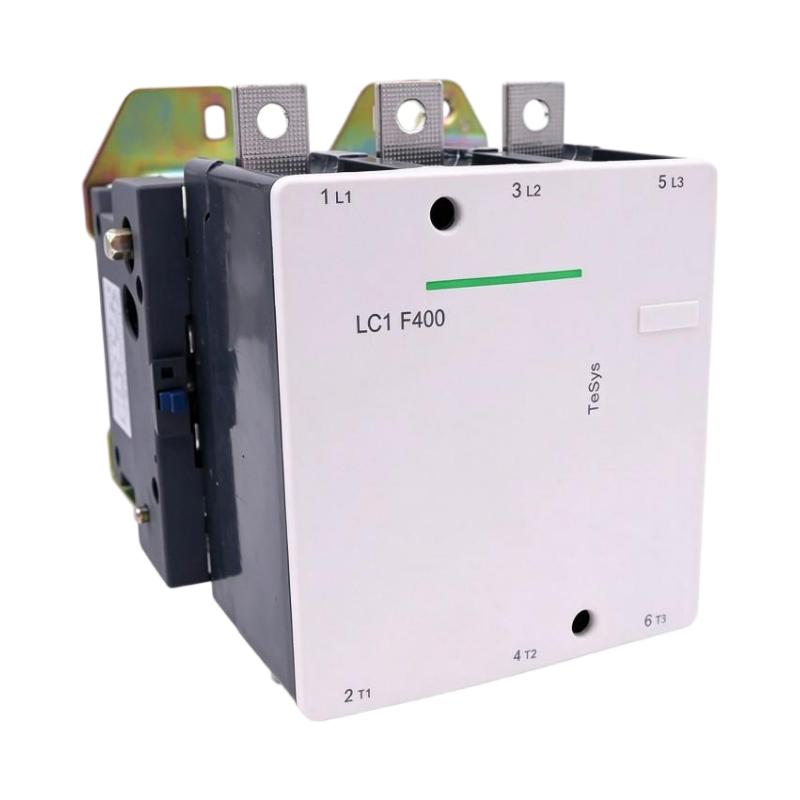
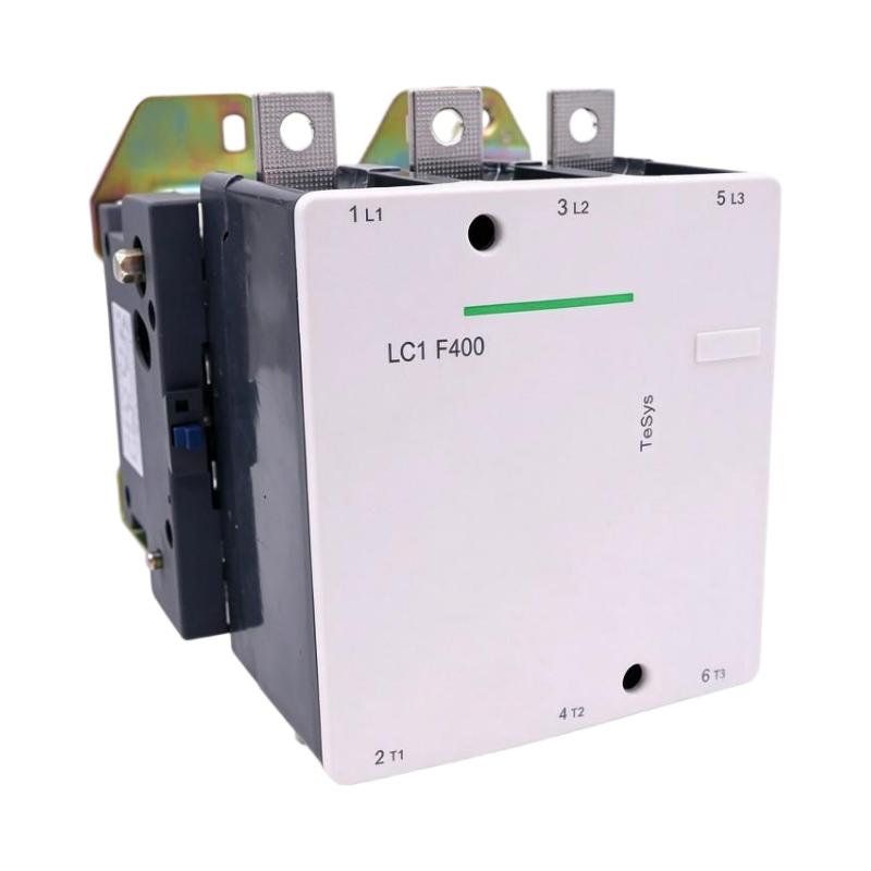
The Schneider Electric LC1F400FE7 TeSys F Contactor is a heavy-duty industrial contactor designed for switching and controlling high-current electrical loads. It belongs to the TeSys F product family and is primarily used in industrial motor-control circuits, power distribution systems, and large electrical equipment.
Contactors are essential components in industrial automation because they allow electrical loads to be switched through an electrically operated control circuit. Instead of manually connecting and disconnecting high-power circuits, an external control signal energizes the contactor coil, causing its main contacts to change state.
The LC1F400FE7 features a three-pole configuration with three normally open main contacts. It has an AC-3 rated operational current of 400 A at voltages up to 440 V AC and a 115 V AC control coil. Its electrical design makes it suitable for demanding motor-starting applications when selected according to the motor’s ratings and operating conditions.
As part of the TeSys F range, this contactor is designed for industrial installations that require reliable switching performance and a robust power-contact arrangement. It can be incorporated into motor starters, electrical control panels, industrial machinery, and other high-current switching systems.
The LC1F400FE7 is a specific catalog configuration. Its coil voltage, number of poles, contact arrangement, and electrical ratings must be considered when selecting a replacement. A contactor from the same product family may have a different coil voltage or operating rating and should not automatically be treated as interchangeable.
Technical Specifications
| Parameter | Specification |
|---|---|
| Brand | Schneider Electric |
| Product Series | TeSys F |
| Model | LC1F400FE7 |
| Product Type | AC Contactor |
| Device Short Name | LC1F |
| Number of Poles | 3P |
| Main Contact Configuration | 3 Normally Open (3 NO) |
| AC-3 Rated Operational Current | 400 A |
| Conventional Free-Air Thermal Current | 500 A at 40°C |
| Rated Operational Voltage | Up to 440 V AC for specified AC-3 rating |
| Control Coil Voltage | 115 V AC |
| Control Circuit Frequency | 40–400 Hz |
| Rated Impulse Withstand Voltage | 8 kV |
| Rated Insulation Voltage | 1000 V AC |
| Contactor Application | Motor Control and Resistive Loads |
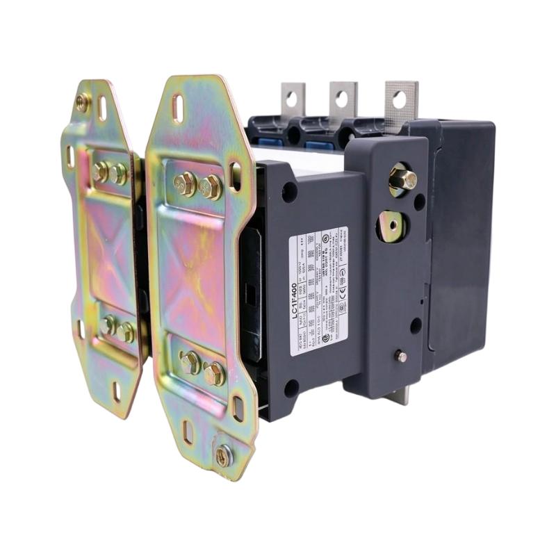
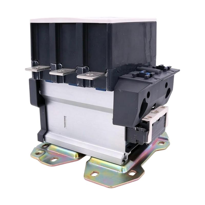
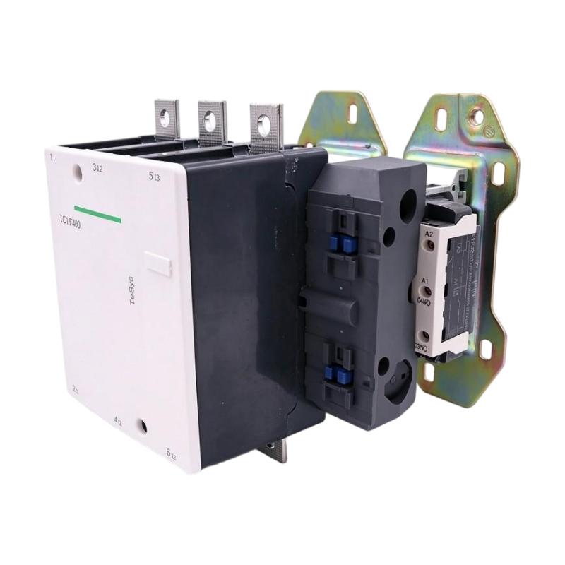
| Mounting Type | Plate Mounting |
| Front Protection | IP20 with appropriate terminal shrouds |
| Dimensions Provided | 206 × 213 × 219 mm |
| Weight Provided | 9.1 kg |
| Product Family | TeSys F |
| Product Lifecycle | Discontinued |
Electrical ratings depend on utilization category, operating voltage, ambient temperature, and installation conditions. Always check the complete manufacturer’s documentation before selecting the contactor for a particular application.
Function and Working Principle
The LC1F400FE7 operates through an electromagnetic switching mechanism. When the control coil receives its specified voltage, an electromagnetic field is generated, moving the contactor’s internal mechanism and changing the state of the main contacts.
When the coil is energized, the three normally open main contacts close, allowing current to flow through the connected power circuit. When the coil is de-energized, the mechanism returns to its normal position and the main contacts open.
1. Electromagnetic Coil Operation
The 115 V AC coil is the control element responsible for operating the contactor. It allows a relatively low-power control circuit to operate a high-current switching device.
A PLC, relay, control switch, or motor-control circuit can provide the appropriate command through a properly designed control arrangement. The coil voltage must match the actual control supply.
Using an incorrect coil voltage can prevent reliable operation or damage the contactor.
2. Three-Pole Main Contact Switching
The LC1F400FE7 contains three normally open main contacts, commonly used to switch the three phases of a three-phase electrical circuit.
When the contactor is energized, the three main contacts close together. This allows power to reach the connected motor or other electrical load.
When the control signal is removed, the main contacts open and interrupt the normal current path. The contactor is therefore commonly used in three-phase motor starters and industrial power-control systems.
3. AC-3 Motor Switching
The contactor has a 400 A AC-3 rated operational current at voltages up to 440 V AC. AC-3 is a utilization category associated with starting squirrel-cage motors and switching them off while they are running.
Motor-starting applications involve electrical and mechanical conditions that differ from switching resistive loads. Consequently, the AC-3 rating is an important selection parameter when the contactor is used for motor control.
The contactor must be selected according to the motor’s rated current, voltage, starting conditions, operating frequency, and application requirements.
4. Electrical Isolation Through Switching
When the contactor opens, its main contacts interrupt the normal power path to the connected load. This enables an external control system to stop the motor or disconnect the controlled circuit.
A contactor is not, by itself, a substitute for a properly rated isolator, circuit breaker, fuse, or safety disconnect device. The complete electrical installation must include suitable protection and isolation equipment.
5. Control Circuit and Power Circuit Separation
The control coil and main power contacts perform different functions. The coil receives the control signal, while the main contacts switch the higher-current load.
This separation allows control logic to operate large industrial loads without routing the entire motor power circuit through PLC output terminals or small control switches.
Role in Industrial Control Systems
The Schneider LC1F400FE7 can serve as a power-switching component within industrial automation and electrical control systems. It is typically installed in a motor-control cabinet or power distribution enclosure.
PLC-Based Motor Control
A programmable logic controller can manage the contactor through an appropriate control relay or output circuit. The PLC processes input signals from sensors, operator stations, and interlocks before issuing a motor-start or stop command.
For example, a PLC may energize the contactor when a production line is ready and remove the command when a machine reaches its stopping condition.
The PLC output and associated control circuit must be designed for the contactor coil’s 115 V AC requirements. A suitable interface or interposing relay may be necessary.
Motor Starter Systems
The LC1F400FE7 can be incorporated into a motor starter arrangement with suitable overload protection, short-circuit protection, and isolation devices.
The contactor provides the switching function, while the other protective components monitor or interrupt abnormal electrical conditions.
A complete motor starter must be engineered according to the motor’s rated current, starting method, duty cycle, and applicable electrical standards.
HMI and Operator Control
An HMI can provide operators with start and stop controls, operating status, and alarm information. In a PLC-based installation, the HMI normally communicates with the controller, which then manages the contactor’s control circuit.
This architecture allows operators to control high-power equipment through a centralized interface while maintaining the required electrical interlocks and safety arrangements.
Power Distribution and Equipment Control
The contactor can also be used in industrial power-control arrangements where electrical loads need to be switched remotely.
Its 400 A AC-3 rating makes it relevant to high-current motor-control applications, although the actual load suitability must be determined using the appropriate utilization category and manufacturer ratings.
Industrial Applications
The LC1F400FE7 is intended for demanding industrial switching applications. Its three-pole arrangement and 400 A AC-3 rating make it suitable for appropriately engineered high-current motor-control systems.
1. Industrial Motor Starters
Large industrial motors are commonly used in manufacturing plants, pumping stations, compressors, and processing equipment.
The contactor provides the electrical switching function required to start and stop compatible motors. It is generally used alongside overload relays, circuit breakers, and other protective components.
2. Pumping Systems
Industrial pumping installations may use high-power motors to transport water, chemicals, or process fluids.
The LC1F400FE7 can be incorporated into a motor-control panel where remote switching and PLC-based operating sequences are required.
The contactor must be selected according to the pump motor’s current, starting characteristics, and operating duty.
3. Compressor Systems
Large compressor installations often require reliable switching of electric motors. A suitable contactor can form part of the compressor’s electrical starter and control arrangement.
The control system may coordinate compressor operation with pressure sensors, temperature monitoring, and equipment interlocks.
4. Industrial HVAC Equipment
Large ventilation systems, cooling equipment, and industrial air-conditioning installations may use high-current motors.
A contactor can provide remote switching for compatible motors and auxiliary equipment. Proper protection and coordination are necessary to manage electrical loads and prevent damage during abnormal operating conditions.
5. Manufacturing and Processing Machinery
Industrial production lines may contain large motors used in mixers, conveyors, crushers, material-handling equipment, and other mechanical systems.
The LC1F400FE7 can be considered for applications requiring a three-pole contactor with a 400 A AC-3 rating and a 115 V AC coil.
6. Electrical Control Cabinets
The contactor can be installed in industrial electrical cabinets as part of a larger motor-control or power-switching assembly.
Its relatively substantial physical size and high-current terminal arrangement require appropriate cabinet space, mounting support, cable routing, and ventilation.
Installation and System Integration
Correct installation is essential for the electrical performance, reliability, and service life of the LC1F400FE7.
1. Verify the Coil Voltage
Before installation, confirm that the control supply is compatible with the contactor’s 115 V AC coil.
The coil voltage is a critical part of the catalog configuration. A contactor with a different coil voltage may have similar external dimensions but will not necessarily operate correctly in the existing control circuit.
Check the control transformer, relay contacts, wiring, and protection arrangements before energizing the coil.
2. Verify Main Circuit Ratings
Confirm that the electrical system matches the contactor’s operating ratings.
For motor applications, the 400 A AC-3 rating should be evaluated together with the motor’s rated current, voltage, starting method, and operating duty.
Do not use the 500 A conventional thermal current rating as a substitute for the AC-3 motor rating. These values represent different operating conditions.
3. Mounting and Cabinet Layout
The supplied dimensions are 206 × 213 × 219 mm, with a listed weight of 9.1 kg.
Ensure that the mounting plate and supporting structure can safely accommodate the contactor. Allow sufficient clearance for the main power terminals, control wiring, terminal protection shrouds, and maintenance access.
The contactor should be mounted in an enclosure suitable for the electrical and environmental conditions of the installation.
4. Main Power Wiring
The three main power poles must be connected according to the manufacturer’s terminal markings and wiring instructions.
Use conductors and cable lugs rated for the expected current and installation temperature. Ensure that terminal connections are tightened to the specified torque.
Loose or incorrectly terminated high-current connections can cause overheating, voltage drops, and equipment failure.
5. Control Circuit Wiring
Connect the control circuit according to the 115 V AC coil specification.
Where a PLC or low-voltage controller is used, an appropriate interface relay or control arrangement may be required. Ensure that electrical interlocks and emergency-stop functions are designed independently of ordinary process-control commands where required by the machine safety design.
6. Protection and Coordination
The contactor should be used with suitable upstream short-circuit protection and appropriate motor overload protection.
Protection devices must be coordinated with the contactor, motor, conductor sizes, and prospective fault current. The contactor alone does not provide complete motor protection.
7. Commissioning and Testing
Before placing the equipment into service:
- Inspect the contactor body and terminals.
- Verify the coil voltage and control wiring.
- Check the main power connections and terminal torque.
- Confirm the phase sequence and motor wiring.
- Test the contactor’s pickup and release operation.
- Verify electrical interlocks and overload protection.
- Check for abnormal noise, vibration, or overheating during operation.
All electrical work should be performed by qualified personnel following applicable safety procedures and manufacturer instructions.
Compatible System Components
The LC1F400FE7 is normally used as part of a complete electrical motor-control arrangement. The following components may be incorporated depending on the application.
| Component | Function | Integration Considerations |
|---|---|---|
| Three-phase AC motor | Converts electrical energy into mechanical power | Match motor current, voltage, and AC-3 requirements |
| PLC | Controls the motor-starting sequence | Use an appropriate interface for the 115 V AC coil |
| Control transformer | Supplies the contactor control circuit | Confirm the secondary voltage and capacity |
| Overload relay | Protects the motor against sustained overload | Select according to motor full-load current |
| Circuit breaker | Provides short-circuit and circuit protection | Coordinate with the contactor and installation fault level |
| Auxiliary contacts | Provide status and interlocking signals | Confirm compatible contact blocks and configuration |
| HMI | Provides operator commands and status monitoring | Typically integrated through the PLC |
| Terminal shrouds | Help protect power terminals against accidental contact | Select the appropriate accessories for the installation |
| Electrical control cabinet | Houses and protects the switching equipment | Ensure adequate space, mounting strength, and ventilation |
The components listed above are examples of equipment used in a complete motor-control system. They are not necessarily included with the LC1F400FE7.
Alternative Models and Replacement Considerations
The LC1F400FE7 has been discontinued. Schneider Electric identifies TeSys Giga contactors as recommended replacement options.
| Alternative Model | Description | Replacement Considerations |
|---|---|---|
| LC1G400EHEA | TeSys Giga, 3-pole, 400 A AC-3, wide-range AC/DC coil | Check coil voltage range and control-circuit compatibility |
| LC1G400KUEN | TeSys Giga, 3-pole, 400 A AC-3, standard version | Verify the 100–250 V AC/DC coil range and installation requirements |
| LC1G400EHEN | TeSys Giga, 3-pole, 400 A AC-3, standard version | Verify the 48–130 V AC/DC coil range and accessory requirements |
| Another LC1F400 variant | TeSys F contactor with a different coil configuration | Confirm the exact coil voltage and complete catalog number |
A replacement should not be selected solely because it has the same 400 A rating. Engineers should compare:
- Number of poles and main contact arrangement.
- AC-3 and other applicable utilization-category ratings.
- Rated operational voltage.
- Coil voltage and control frequency.
- Main terminal arrangement.
- Mounting dimensions and mechanical clearances.
- Auxiliary contact configuration.
- Short-circuit coordination requirements.
- Required accessories and terminal protection.
When upgrading from TeSys F to TeSys Giga, check the manufacturer’s replacement guidance and installation documentation. Mechanical dimensions, wiring arrangements, accessories, and control characteristics may differ.
Key Advantages
High-Current Switching Capability
The 400 A AC-3 rating makes the LC1F400FE7 suitable for selected high-current motor-control applications when correctly matched to the electrical load.
Three-Pole Contact Configuration
Three normally open main contacts allow the contactor to switch the three phases of a compatible three-phase electrical circuit.
115 V AC Control Coil
The 115 V AC coil supports integration with compatible industrial control circuits and appropriately designed relay interfaces.
Industrial Motor-Control Design
The TeSys F product family is designed for industrial switching applications, including motor control and resistive loads.
Robust Electrical Ratings
The contactor has a 500 A conventional free-air thermal current rating and an 8 kV rated impulse withstand voltage, subject to the relevant operating conditions and standards.
Integration with Automation Systems
The contactor can be incorporated into PLC-controlled motor starters, industrial control cabinets, and automated equipment through an appropriately designed control circuit.
Technical FAQs
1. What is the Schneider Electric LC1F400FE7?
The LC1F400FE7 is a three-pole TeSys F AC contactor designed for industrial motor control and resistive-load switching.
2. What is its rated AC-3 current?
Its rated operational current is 400 A under AC-3 conditions at voltages up to 440 V AC.
3. What is the coil voltage?
The LC1F400FE7 uses a 115 V AC control coil. Confirm the coil marking before connecting the control supply.
4. How many main contacts does it have?
It has three main poles, with three normally open contacts (3 NO).
5. Can it control a three-phase motor?
Yes. It can be used in an appropriately designed three-phase motor starter, provided that the motor and application meet the contactor’s electrical ratings.
6. Does the contactor provide overload protection?
No. A contactor performs switching. Suitable motor overload protection and short-circuit protection must be provided by other correctly selected components.
7. Is the LC1F400FE7 still available from Schneider Electric?
The model was discontinued on December 31, 2023. Existing stock, surplus units, and replacement products may be available through industrial suppliers.
8. What are the recommended replacement models?
Schneider Electric lists LC1G400EHEA, LC1G400KUEN, and LC1G400EHEN as recommended replacement options. Their coil ranges and installation requirements should be checked before substitution.
9. Can another LC1F400 model replace it?
Not automatically. Different LC1F400 suffixes may indicate different coil voltages or configurations. Verify the complete catalog number and electrical specifications.
10. What should be checked before purchasing?
Confirm the complete model number, coil voltage, contact configuration, product condition, terminal condition, and any included accessories. For used equipment, request photographs and functional test information where available.
Procurement and Maintenance Recommendations
When purchasing the Schneider Electric LC1F400FE7, verify the complete catalog number and the 115 V AC coil specification. This is particularly important when sourcing replacement contactors for existing motor-control panels.
For surplus or discontinued units, inspect the main contacts, coil terminals, housing, operating mechanism, and power terminals. Confirm whether the product is new, unused surplus, refurbished, or previously installed. Request clear photographs and test documentation where possible.
During routine maintenance, qualified personnel should inspect terminal tightness, contact condition, signs of overheating, mechanical operation, and control-circuit wiring. Maintenance intervals should reflect the operating frequency, load characteristics, and environmental conditions.
For replacement projects, compare the electrical ratings and mechanical arrangement of the original contactor with the proposed replacement. If changing to a TeSys Giga model, review the updated mounting, wiring, coil, and accessory requirements before modifying the control cabinet.
Conclusion
The Schneider Electric LC1F400FE7 TeSys F Contactor is a three-pole industrial contactor with a 400 A AC-3 rated operational current and a 115 V AC control coil. It is designed for high-current motor-control and resistive-load switching applications in industrial electrical systems.
Its main characteristics include three normally open power contacts, a 500 A conventional thermal current rating, and an industrial contactor design suitable for integration into motor starters and automation control cabinets.
Although the LC1F400FE7 has been discontinued, it remains relevant to maintenance and replacement projects involving existing TeSys F installations. Accurate catalog-number verification, coil-voltage matching, and electrical compatibility checks are essential when sourcing or selecting a replacement.