

ProductPRODUCT
Featured products




Contact Us
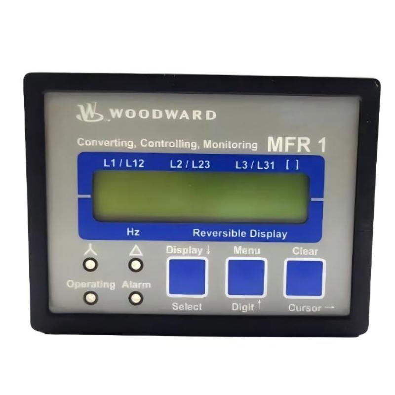
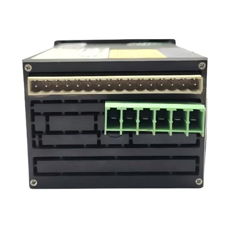

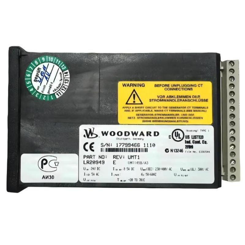
- Woodward
- LR20949
- UMT1 Measuring Transducer
- USA
- 130 × 80 × 50 mm
- 0.45 kg
- Xiamen, China
- New & In Stock
- T/T, PayPal, Western Union
- 1 Year
- 1-3 Working Days
- DHL, UPS, TNT, FedEx and EMS.
- 24-Hour Service
- COO
- 8
Our advantage

Global Logistics
We have a 10-year logistics and express cooperation agreement, so our products can be shipped to any place in the world.

Brand new and original
Our products are imported in bulk from the place of origin. Because of the cooperative relationship, our products are all original and 100% new.

24-hour service
We provide 7*24 hours service to our customers. We will be there whenever you need us.

Price advantage
All our products are priced very favorably because we have our own warehouse and supply.
| Company Information | |||
| [email protected] | |||
| Mobile | +8615980777398 | ||
| +8615980777398 | |||
| 15980777398 |
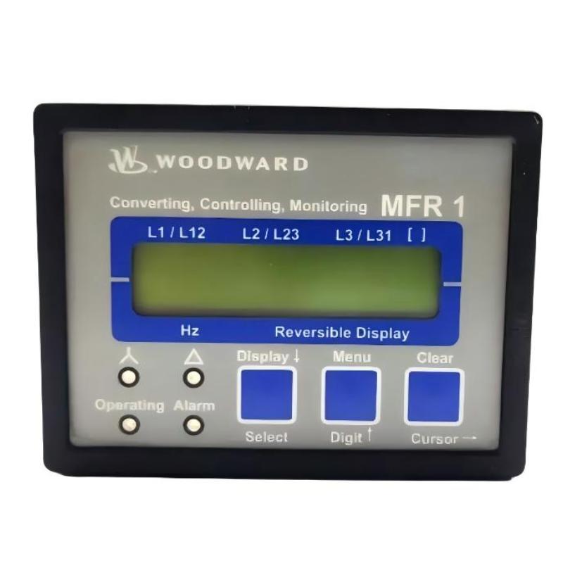
Product Overview
The Woodward LR20949 UMT1 Measuring Transducer is an electrical measurement device used to acquire and process three-phase voltage and current signals in power-generation and industrial electrical systems. Associated with the UMT145B/A3 configuration, it calculates electrical operating values from true RMS measurements and makes the resulting data available through its display and configured signal outputs.
In a generator control cabinet, the transducer can provide the electrical measurements needed to monitor generator loading and operating conditions. Voltage and current measurements are used to calculate active power, reactive power, apparent power, and power factor. Depending on the configured functions, the unit can also track accumulated energy and transfer selected measurement values to a higher-level controller.
The A3 configuration is relevant when integrating the transducer into an existing analog measurement circuit. Its configurable analog output allows selected electrical quantities to be represented as current signals for compatible monitoring equipment or control-system inputs. This is useful when the receiving controller needs a continuous measurement signal rather than relying exclusively on digital communication.
The LR20949 is therefore best evaluated as part of the complete measurement chain. The voltage-transformer ratio, current-transformer ratio, selected measuring system, analog output assignment, and receiving controller’s input range all affect the accuracy and usefulness of the reported values. These settings should be verified when commissioning or replacing the unit.
Technical Specifications
| Parameter | Specification |
|---|---|
| Manufacturer | Woodward |
| Model | LR20949 |
| Product Family | UMT1 |
| Product Type | Measuring Transducer |
| Associated Configuration | UMT145B/A3 |
| Measurement Method | True RMS |
| Measured Inputs | Three-phase voltage and current |
| Voltage Measurement Configuration | 400 V rated phase-to-phase configuration associated with the UMT145 variant |
| Current Input | 5 A rated current-transformer secondary |
| Analog Output | Configurable current output; A3 option |
| Available Output Ranges | -20 to +20 mA, 0 to 20 mA, or 4 to 20 mA, subject to configuration |
| Calculated Quantities | Active power, reactive power, apparent power, power factor, and energy |
| Display | Two-line, 16-character LCD |
| Configuration Interface | Front-panel controls; configuration depends on the installed version |
| Housing | APRANORM DIN 43 700 |
| Mounting | Flush-panel mounting |
| Size | 130 × 80 × 50 mm |
| Weight | 0.45 kg |
Product Features
- True RMS measurement: Measures electrical quantities using true RMS values, supporting the monitoring of AC systems with varying waveforms within the unit’s specified operating limits.
- Three-phase electrical monitoring: Acquires voltage and current measurements for configured three-phase systems.
- Power calculation: Derives active, reactive, and apparent power from the measured electrical quantities.
- Power factor monitoring: Provides power factor information for assessing generator and load operating conditions.
- Configurable analog output: Allows a selected measurement to be transmitted as a current signal within the available output ranges.
- Local LCD display: Presents electrical measurements and configuration information through a two-line display.
- Energy measurement: Supports accumulated energy measurements and associated functions when configured.
- System-dependent measurement setup: Allows the measuring arrangement to be selected to suit the connected electrical network.
- Control-system integration: Supplies measurement information to compatible analog inputs or supported communication interfaces, depending on the installed configuration.
Working Principle
The LR20949 receives voltage and current signals from the electrical measurement circuits connected to the UMT1. It processes the signals using true RMS measurement and calculates the corresponding electrical quantities. Selected values can then be displayed locally or converted into analog output signals for use by another device.
A typical measurement arrangement follows this sequence:
Voltage Transformers / Voltage Inputs + Current Transformers → LR20949 UMT1 → Analog Output → PLC or Monitoring System
During normal operation, the transducer continuously evaluates the connected electrical signals. The measured voltage and current values form the basis for calculating power and power factor. Where energy measurement is configured, the unit also accumulates the corresponding energy values over time.
For example, in a generator installation, the controller may need a continuous signal representing active power. The LR20949 can be configured to assign the selected measurement to an analog output. A compatible PLC analog input then receives the scaled current signal and uses it for display, load monitoring, or supervisory control logic.
The analog output range and scaling must match the receiving input. If the transducer is configured for 4–20 mA while the controller expects a different range, the resulting readings may be incorrect even when the electrical measurements themselves are valid. Engineers should therefore verify the assigned quantity, output limits, and controller scaling together.
Correct measurement also depends on the voltage and current transformer settings. An incorrect transformer ratio or measuring-system selection can cause the calculated power values to differ from the actual operating conditions. The transducer should be commissioned with the electrical system configuration entered correctly before its readings are used for operational decisions.
Role in a Generator Monitoring Architecture
The LR20949 functions as a measurement and signal-conversion component between the electrical power circuit and the control or monitoring system. It supplies processed electrical data rather than directly controlling the generator’s main power circuit.
Generator Electrical Circuit → Voltage / Current Measurement → LR20949 UMT1 → PLC or Supervisory System
| System Element | Function |
|---|---|
| Generator or Three-Phase Supply | Provides the electrical quantities being monitored |
| Voltage Measurement Circuit | Supplies voltage signals to the transducer |
| Current Transformer | Provides the current signal for measurement |
| LR20949 UMT1 | Measures electrical quantities and calculates derived values |
| Analog Output Circuit | Transfers a selected measurement as a scaled current signal |
| PLC Analog Input | Receives and scales the transducer output |
| Generator Controller | Uses available measurement data in the wider control sequence |
| Operator Display or Monitoring System | Presents electrical values for operational review |
| Energy Monitoring Function | Uses accumulated energy values where configured |
The transducer’s output is only one part of the measurement chain. Correct transformer wiring, signal scaling, controller configuration, and grounding arrangements are all necessary to obtain meaningful readings.
Industrial Applications
| Application | Typical Use |
|---|---|
| Generator Monitoring | Measuring voltage, current, power, and power factor |
| Power Generation Control Cabinets | Supplying electrical measurements to the control system |
| Industrial Power Distribution | Monitoring electrical conditions in three-phase systems |
| Generator Load Monitoring | Providing active and reactive power information |
| Electrical Energy Monitoring | Tracking accumulated energy where configured |
| Supervisory Control Systems | Transferring selected measurements to PLC analog inputs |
| Power Factor Assessment | Reviewing the relationship between active and apparent power |
| Electrical Commissioning | Verifying measurement signals and calculated operating values |
| Utility and Auxiliary Power Systems | Monitoring electrical quantities in compatible installations |
| Legacy Generator Control Systems | Maintaining an existing UMT1-based measurement arrangement |
The LR20949 is most appropriate where the required measurement functions, transformer inputs, and output signals match the installation. It should not be treated as a substitute for a dedicated protective relay where independent fault detection and circuit tripping are required.
Installation and Maintenance
- Verify the model identification: Confirm that the unit is LR20949 and check the associated UMT1 configuration before installation.
- Check the voltage measurement arrangement: Verify the rated voltage configuration and the connected voltage-transformer ratios against the electrical drawings.
- Confirm the current-transformer rating: Ensure that the current input and CT secondary circuit match the specified 5 A configuration.
- Select the correct measuring system: Check whether the installation uses the appropriate three-phase, three-wire, or four-wire measurement arrangement.
- Inspect the panel mounting: Confirm that the panel cutout, retaining hardware, and enclosure arrangement are suitable for the actual unit.
- Isolate the electrical circuits: Follow approved electrical safety procedures before disconnecting voltage and current measurement wiring.
- Check the auxiliary supply: Verify the supply requirements of the installed version before energizing the transducer.
- Inspect analog output wiring: Check polarity, terminal assignments, cable condition, and the receiving controller’s input configuration.
- Verify output scaling: Confirm the selected measurement, analog output range, and corresponding PLC scaling parameters.
- Check displayed measurements: Compare the displayed voltage and current values with suitable reference measurements during commissioning.
- Test calculated electrical quantities: Verify power and power factor readings under known operating conditions where practical.
- Document the final configuration: Record transformer ratios, measuring-system selection, output assignments, and commissioning results for future maintenance.
Never open a current-transformer secondary circuit while primary current is flowing unless it has been made safe using an approved shorting and isolation arrangement. Incorrect transformer wiring can also produce misleading power calculations. All electrical checks should be carried out by qualified personnel using suitable test equipment.
Compatible System Components
The LR20949 requires correctly rated voltage and current measurement circuits and a receiving system compatible with its configured outputs. The exact arrangement depends on the generator installation and the measurement functions selected during configuration.
| Component | Function |
|---|---|
| Voltage Transformer or Potential Transformer | Provides the required voltage measurement signal |
| 5 A Current Transformer | Supplies the rated current input |
| PLC Analog Input Module | Receives the configured analog current output |
| Generator Controller | Uses measurement data in the wider control architecture |
| Analog Signal Cable | Transfers the selected measurement to the receiving device |
| Auxiliary Power Supply | Powers the transducer according to the installed version’s requirements |
| Electrical Terminal Blocks | Organize voltage, current, supply, and signal wiring |
| Panel Mounting Hardware | Secures the unit within the control cabinet |
| Configuration Controls | Allow supported measurement and output parameters to be adjusted |
| Electrical Test Instruments | Support verification of measurement accuracy and output scaling |
Recommended Related Models
The following models are related to the Woodward UMT1 measurement-transducer family or to associated electrical measurement applications. Confirm the input ratings, output options, and interface requirements before selecting a substitute.
| Model | Product Type | Relevance |
|---|---|---|
| Woodward UMT141B/A3SU | UMT1 Measuring Transducer | Related UMT1 configuration with 1 A current input and communication option |
| Woodward UMT145B/A6 | UMT1 Measuring Transducer | Related configuration with 5 A current input and multiple configurable analog outputs |
| Woodward UMT145B | UMT1 Measuring Transducer | Related 5 A measurement configuration |
| Woodward UMT115B/A6 | UMT1 Measuring Transducer | Related configuration using a 100 V voltage-transformer input and 5 A current input |
| Woodward UMT1 | Measuring Transducer | Same product family for three-phase electrical measurement |
| Woodward MFR300 | Multifunctional Relay | Related power-system monitoring equipment with different measurement and control functions |
Key Advantages
- True RMS measurement of three-phase electrical quantities.
- Calculation of active power, reactive power, apparent power, and power factor.
- Configurable analog current output for integration with compatible controllers.
- Local display for checking electrical measurements.
- Energy measurement functions when configured.
- Suitable for generator monitoring and industrial power measurement systems.
Technical FAQs
Which measurements can the LR20949 provide to a generator controller?
The UMT1 measures voltage and current and calculates values such as active power, reactive power, apparent power, and power factor. Energy measurement is also available where configured. The actual values presented to the controller depend on the selected output assignment and installed configuration.
What must be checked when connecting the A3 analog output to a PLC?
Verify the selected measurement, output range, signal polarity, and receiving analog input configuration. The PLC scaling must correspond to the transducer’s configured current range; otherwise, the displayed engineering values may be incorrect.
Why might the displayed power value differ from the generator controller’s reading?
Check the voltage-transformer and current-transformer ratios, phase assignments, CT polarity, and selected measuring-system configuration. Incorrect phase relationships or scaling can affect calculated power even when the individual voltage and current readings appear reasonable.
Can the LR20949 replace a dedicated generator protection relay?
Not as a direct functional equivalent. The LR20949 is a measuring transducer intended to measure and transmit electrical quantities. A dedicated protection relay performs protection logic and initiates trip actions according to its specified functions. The appropriate device depends on whether the requirement is measurement, protection, or both.