

ProductPRODUCT
Featured products
Contact Us
- Woodward
- LR20025
- MFR13 Multifunctional Relay
- USA
- 96 × 72 × 130 mm
- 0.907 kg
- Xiamen, China
- New & In Stock
- T/T, PayPal, Western Union
- 1 Year
- 1-3 Working Days
- DHL, UPS, TNT, FedEx and EMS.
- 24-Hour Service
- COO
- 8
Our advantage

Global Logistics
We have a 10-year logistics and express cooperation agreement, so our products can be shipped to any place in the world.

Brand new and original
Our products are imported in bulk from the place of origin. Because of the cooperative relationship, our products are all original and 100% new.

24-hour service
We provide 7*24 hours service to our customers. We will be there whenever you need us.

Price advantage
All our products are priced very favorably because we have our own warehouse and supply.
| Company Information | |||
| [email protected] | |||
| Mobile | +8615980777398 | ||
| +8615980777398 | |||
| 15980777398 |
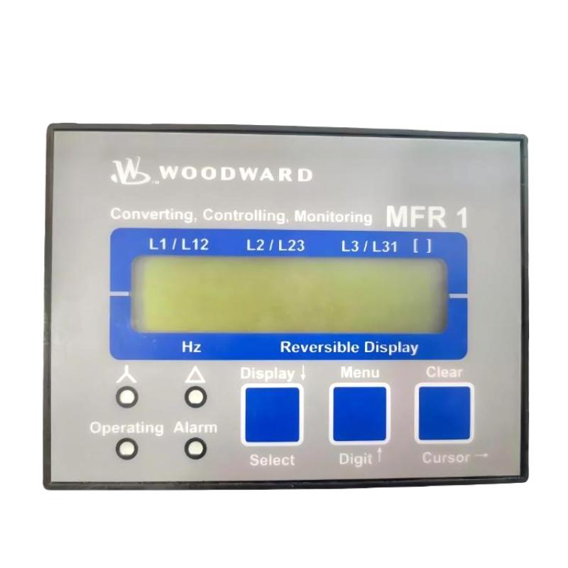
Product Overview
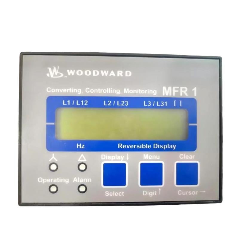
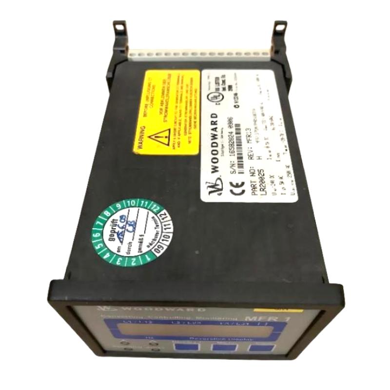
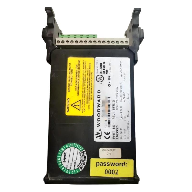
The Woodward LR20025 is a customized MFR13 multifunctional relay developed for electrical monitoring and protection in wind turbine installations. Its documented configuration, identified as MFR1375M/PMRSU03UV, combines voltage, frequency, and power monitoring with programmable relay outputs. In a wind turbine control cabinet, the relay evaluates electrical operating conditions and communicates relevant information to the upper-level PLC, allowing the wider control system to respond to changes in generator or grid conditions.
The LR20025 is particularly relevant to wind power installations using a dedicated MFR13 configuration. Rather than functioning as a general-purpose interface module, it combines electrical measurement, protection-related functions, local indication, and control-system communication in one device. The relay measures three-phase electrical quantities and uses its configured logic and output contacts to support the required monitoring and control sequence.
Communication is an important part of this specific model’s application. The LR20025 uses a customized CAN bus protocol associated with the SU03 option. This configuration matters when maintaining an existing wind turbine controller because a replacement must preserve the communication behavior expected by the upper-level PLC, not merely match the relay’s measurement ratings.
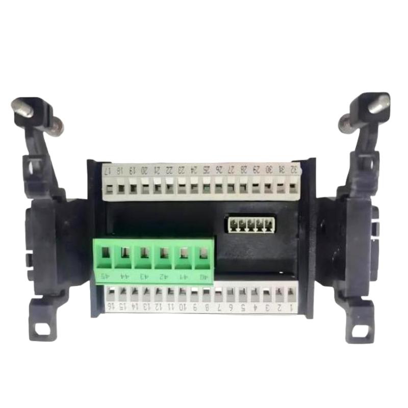
The relay also has a two-line numeric display, one discrete input, and eight discrete outputs in the documented configuration. These features support local status checking and external control-circuit integration. When replacing an installed unit, engineers should verify the CAN protocol option, measurement connections, output assignments, and existing configuration before returning the turbine control system to service.
Technical Specifications
| Parameter | Specification |
|---|---|
| Manufacturer | Woodward |
| Model | LR20025 |
| Product Family | MFR13 |
| Product Type | Multifunctional Relay |
| Customized Configuration | MFR1375M/PMRSU03UV |
| Application | Wind turbine electrical monitoring and protection |
| Auxiliary Supply | 24 V DC |
| Voltage Measurement Range | 250–690 VAC |
| Voltage Frequency | 50/60 Hz |
| Current Measurement Range | 0.5–5 A |
| Measurement Accuracy | Class 1 |
| Monitored Quantities | Voltage, frequency, and power |
| Discrete Inputs | 1 |
| Discrete Outputs | 8 |
| Communication Interface | CAN bus |
| Communication Configuration | Customized SU03 protocol |
| Display | Two-line numeric display |
| Configuration Software | LeoPC |
| Housing | APRANORM DIN 43 700 |
| Mounting | Front-panel mounting; optional rear DIN-rail brackets for applicable configurations |
| Size | 96 × 72 × 130 mm |
| Weight | 0.907 kg |
Product Features
- Multifunctional electrical monitoring: Measures voltage, frequency, and power within the configured application.
- Three-phase measurement capability: Supports electrical monitoring for generator and switchgear installations.
- 690 VAC voltage sensing: Accommodates the documented voltage-measurement configuration.
- 0.5–5 A current input: Supports the corresponding current-transformer measurement circuit.
- Class 1 measurement accuracy: Provides the specified measurement accuracy for the documented configuration.
- Eight discrete outputs: Allows multiple configured relay signals to be integrated into external control circuits.
- One discrete input: Accepts an external discrete signal for the configured control function.
- Customized CAN communication: Uses the SU03 protocol configuration for communication with the upper-level PLC.
- Two-line numeric display: Allows local inspection of displayed operating values and status information.
- PC-based configuration: Uses LeoPC for supported configuration and parameter-management tasks.
Working Principle
The LR20025 acquires electrical measurements from the connected voltage and current sensing circuits. Its internal processing evaluates the measured quantities against the configured monitoring and protection parameters. When a programmed condition is met, the relay can change the state of its assigned outputs or communicate relevant information to the upper-level controller.
A typical wind turbine control arrangement follows this sequence:
Generator / Electrical Measurement Circuits → LR20025 MFR13 → CAN Bus → Upper-Level PLC
LR20025 Relay Outputs → External Control Circuits
During normal operation, the relay monitors the electrical quantities configured for the installation. Voltage and frequency measurements help the control system assess electrical operating conditions, while power measurement provides information about the generator’s output. The upper-level PLC can use the communicated data as part of the turbine’s operating sequence.
For example, if the measured voltage or frequency moves outside its configured operating limits, the relay’s programmed logic can initiate the corresponding output response. The PLC may then coordinate the required control action according to the turbine’s operating logic. The precise response depends on the installed configuration, protection settings, and external circuits.
The customized CAN interface is especially important in the LR20025 application. The relay communicates with the upper-level PLC using the SU03 protocol, so the communication settings and expected data structure must remain compatible. Installing a relay with a different CAN protocol may prevent the controller from interpreting the transmitted information correctly, even if the replacement supports similar electrical measurements.
The eight discrete outputs provide additional integration points for configured control signals. Their actual functions depend on the programmed assignments and the wiring of the turbine control cabinet. Engineers should therefore verify the output mapping rather than assume that every LR20025 installation uses identical assignments.
Role in a Wind Turbine Control Architecture
The LR20025 acts as an electrical measurement and multifunctional relay within the turbine’s control architecture. It processes electrical quantities locally and exchanges information with the upper-level PLC through its customized CAN bus connection.
Generator Measurement Circuits → LR20025 MFR13 → CAN Bus → Turbine PLC
LR20025 Discrete Outputs → Assigned Control and Signaling Circuits
| System Element | Function |
|---|---|
| Generator | Produces the electrical output monitored by the control system |
| Voltage Measurement Circuit | Supplies the voltage signals required by the relay |
| Current Transformer | Supplies the current measurement signal |
| LR20025 MFR13 | Monitors configured electrical quantities and manages assigned relay outputs |
| CAN Bus | Transfers configured data between the relay and upper-level PLC |
| Upper-Level PLC | Coordinates turbine operating sequences using available measurement and status information |
| Discrete Input Circuit | Supplies the external input signal assigned to the relay |
| Discrete Output Circuits | Carry configured relay signals to external equipment |
| Operator or Maintenance Interface | Supports system inspection and configuration where provided |
| Circuit Breaker and Control Circuits | Execute switching actions according to the overall protection and control design |
The customized communication configuration and external wiring must be verified as part of commissioning. The relay’s local measurements, discrete outputs, and PLC communication should be tested together to confirm that the intended turbine control sequence operates correctly.
Industrial Applications
| Application | Typical Use |
|---|---|
| Wind Turbine Generator Systems | Monitoring voltage, frequency, and power |
| Wind Farm Electrical Control | Providing measurement and status data to the turbine PLC |
| Generator Switchgear | Supporting electrical monitoring and configured relay functions |
| Three-Phase Power Monitoring | Evaluating electrical quantities in compatible measurement circuits |
| Turbine Control Cabinets | Integrating measurement and discrete output functions |
| Wind Turbine Retrofit Projects | Maintaining the existing MFR13 measurement and communication arrangement |
| Electrical Operating-Condition Monitoring | Detecting configured voltage and frequency deviations |
| Industrial Power Systems | Supporting applications where the required MFR13 configuration is suitable |
The LR20025 is most directly associated with wind turbine applications that use its customized SU03 CAN protocol. For other electrical installations, engineers must verify that the measurement range, control functions, communication interface, and protection requirements match the intended application.
Installation and Maintenance
- Verify the complete part number: Confirm that the installed relay is Woodward LR20025 and identify the customized MFR13 configuration before beginning replacement work.
- Check the auxiliary supply: Verify the 24 V DC supply and confirm the correct terminal connections before energizing the relay.
- Inspect voltage measurement wiring: Check the phase connections, voltage sensing circuit, and terminal assignments against the turbine wiring diagram.
- Verify current-transformer connections: Confirm that the current input matches the specified 0.5–5 A measurement configuration and inspect the secondary wiring for errors.
- Review the CAN bus connection: Check the communication cable, connector condition, wiring arrangement, and connection to the upper-level PLC.
- Confirm the SU03 protocol configuration: Ensure that the customized CAN protocol and associated communication settings match the existing turbine control system.
- Inspect discrete input wiring: Verify the external signal connected to the relay’s single discrete input and confirm its intended function.
- Check discrete output assignments: Compare the eight output connections with the control cabinet drawings and verify the function assigned to each output.
- Review protection parameters: Check the configured voltage, frequency, and power monitoring settings against the approved application requirements.
- Verify display operation: Confirm that the two-line numeric display operates correctly and presents the expected information after startup.
- Perform a controlled functional test: Test measurement values, CAN communication, discrete inputs, and output responses under approved commissioning conditions.
- Document the final configuration: Record the relay identification, measurement settings, CAN parameters, input/output assignments, and functional test results.
Before disconnecting voltage or current measurement circuits, follow the applicable electrical isolation procedures. Current-transformer secondary circuits must not be opened while primary current is flowing unless the circuit has been made safe using the proper shorting and isolation arrangements. After installation, confirm that all wiring and protection functions have been checked before returning the turbine to operation.
Compatible System Components
The LR20025 operates within a wider turbine electrical monitoring and control arrangement. Compatibility depends on the customized SU03 communication protocol, measurement circuit ratings, and the external control functions assigned to the relay.
| Component | Function |
|---|---|
| Upper-Level Turbine PLC | Receives configured relay data and coordinates turbine control sequences |
| Compatible CAN Bus Network | Carries communication between the LR20025 and the PLC |
| Voltage Measurement Circuit | Supplies the voltage signals used for monitoring |
| Compatible Current Transformer | Provides the required current measurement input |
| 24 V DC Power Supply | Supplies the relay’s auxiliary operating power |
| Discrete Input Circuit | Provides the external signal assigned to the relay input |
| External Relay and Control Circuits | Use the configured outputs for signaling or control |
| Generator Switchgear | Provides the electrical switching arrangement associated with the generator |
| PC Configuration Connection | Supports configuration tasks using compatible LeoPC software |
| Electrical Control Cabinet | Houses the relay, wiring, and associated control equipment |
Recommended Related Models
| Model | Product Type | Relevance |
|---|---|---|
| Woodward 8444-1093 MFR300-75M/SU03 | Multifunctional Relay | Documented replacement configuration with compatible SU03 CAN protocol |
| Woodward MFR13 | Multifunctional Protection Relay | Same product family as the LR20025 |
| Woodward MFR12 | Multifunctional Relay | Related multifunctional electrical monitoring relay |
| Woodward MFR300-71M/SU08 | Multifunctional Relay | Related customized relay used in wind turbine applications |
| Woodward MFR300-75M | Multifunctional Relay | Related MFR300 configuration for electrical monitoring |
| Woodward MFR500 | Multifunctional Relay | Related multifunctional relay family for power-generation applications |
Key Advantages
- Combines voltage, frequency, and power monitoring in one relay.
- Supports 250–690 VAC voltage sensing and 0.5–5 A current measurement.
- Provides eight discrete outputs and one discrete input in the documented configuration.
- Communicates with the upper-level PLC through a customized SU03 CAN protocol.
- Includes a two-line numeric display for local operating checks.
- Supports configuration using LeoPC software.
Technical FAQs
Why is the SU03 CAN protocol important when replacing an LR20025?
The LR20025 uses a customized CAN protocol associated with the SU03 option. The upper-level PLC expects data in the corresponding format, so a replacement must support compatible communication behavior. A relay with a similar measurement range but a different protocol may require changes to the control-system configuration.
Which electrical quantities can the LR20025 monitor?
The documented LR20025 configuration monitors voltage, frequency, and power. Its voltage measurement range is specified as 250–690 VAC, and its current measurement range is 0.5–5 A. The actual measurement wiring and configured functions should be checked against the installed turbine application.
What should be checked if the upper-level PLC cannot communicate with the relay?
Inspect the CAN bus wiring and connections, confirm that the relay and PLC use compatible communication settings, and verify the customized SU03 protocol configuration. Also check the relay’s auxiliary supply and review the control system’s communication diagnostics before replacing hardware.
Can the Woodward 8444-1093 MFR300-75M/SU03 replace the LR20025 directly?
Woodward’s application documentation identifies the 8444-1093 MFR300-75M/SU03 as a replacement with a compatible CAN protocol for the LR20025 wind turbine application. The documented compatibility allows the upper-level PLC to be retained without protocol-related changes. However, the replacement has a different physical design, display arrangement, and input/output configuration, so installation wiring and system functions must still be checked before commissioning.