

ProductPRODUCT
Featured products
Contact Us
- Schneider
- XCC-1510PSM05Y
- XCC Incremental Encoder
- France
- 58 mm
- 0.465 kg
- Xiamen, China
- New & In Stock
- T/T, PayPal, Western Union
- 1 Year
- 1-3 Working Days
- DHL, UPS, TNT, FedEx and EMS.
- 24-Hour Service
- COO
- 8
Our advantage

Global Logistics
We have a 10-year logistics and express cooperation agreement, so our products can be shipped to any place in the world.

Brand new and original
Our products are imported in bulk from the place of origin. Because of the cooperative relationship, our products are all original and 100% new.

24-hour service
We provide 7*24 hours service to our customers. We will be there whenever you need us.

Price advantage
All our products are priced very favorably because we have our own warehouse and supply.
| Company Information | |||
| [email protected] | |||
| Mobile | +8615980777398 | ||
| +8615980777398 | |||
| 15980777398 |
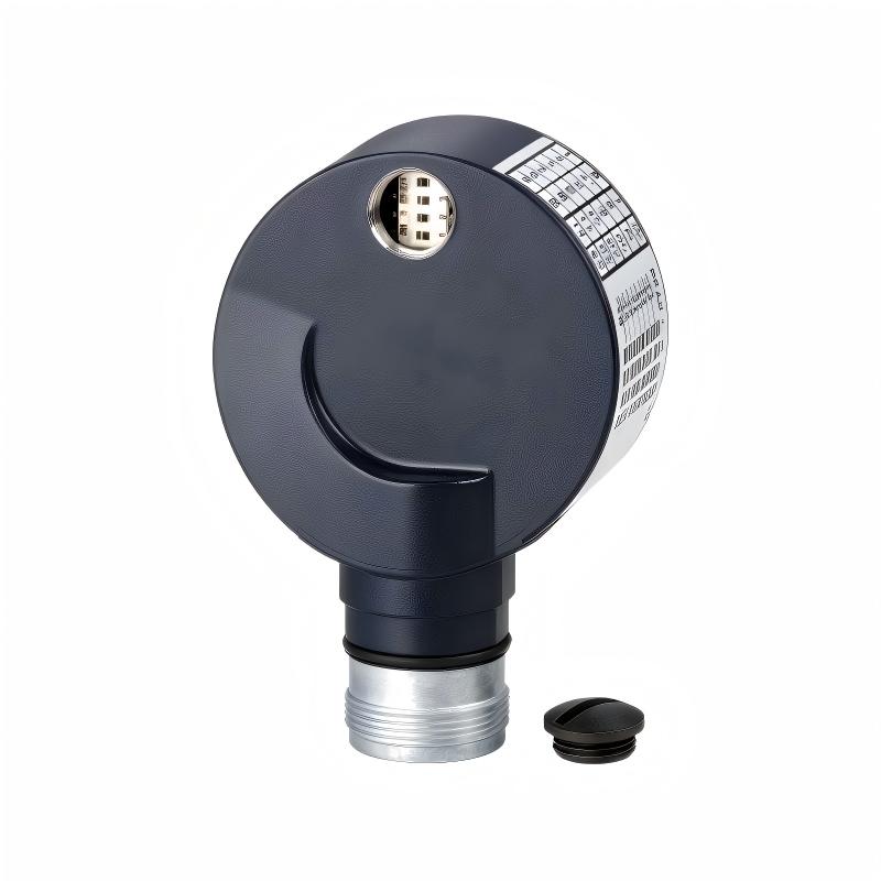
1. Product Overview
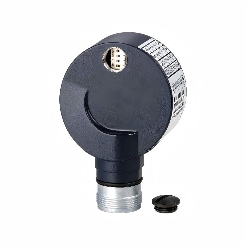
The Schneider Electric XCC-1510PSM05Y is an incremental rotary encoder from the OsiSense XCC product family. It is designed to measure rotational movement and provide digital feedback for industrial automation, motion control, and machine positioning applications. By converting shaft rotation into electrical pulse signals, the encoder enables a control system to monitor rotational speed, determine movement direction when the appropriate output channels are evaluated, and calculate relative displacement.
With a 58 mm housing diameter and a 10 mm solid shaft, the XCC-1510PSM05Y is suitable for installation on compatible rotating machinery, drive assemblies, and mechanical transmission systems. Its Type Y push-pull output stage supports integration with compatible electronic counting devices and automation controllers. The encoder operates from a 5–30 V DC supply, providing flexibility for industrial control systems designed around different low-voltage DC power arrangements.
One of the model’s important characteristics is its parameterizable resolution. The documented configuration range is 500 to 8,000 points per revolution, allowing the encoder to be configured for different measurement requirements within its supported range. This flexibility can help equipment designers balance feedback resolution, counting frequency, and controller processing requirements.
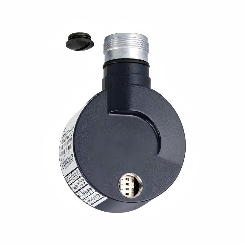
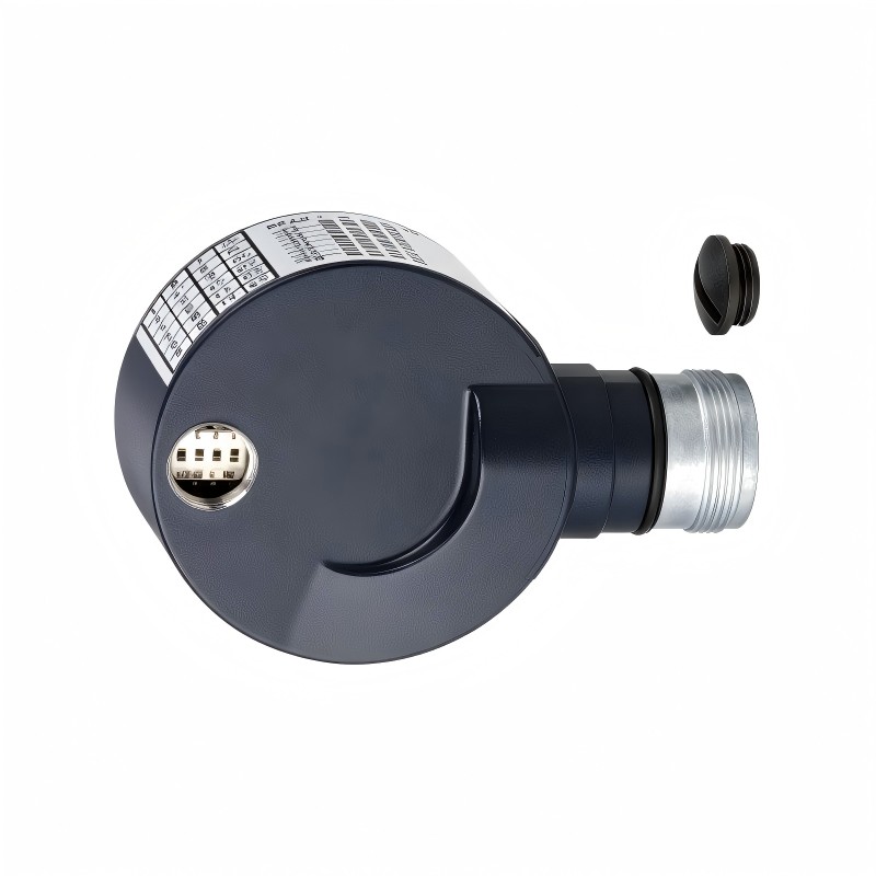
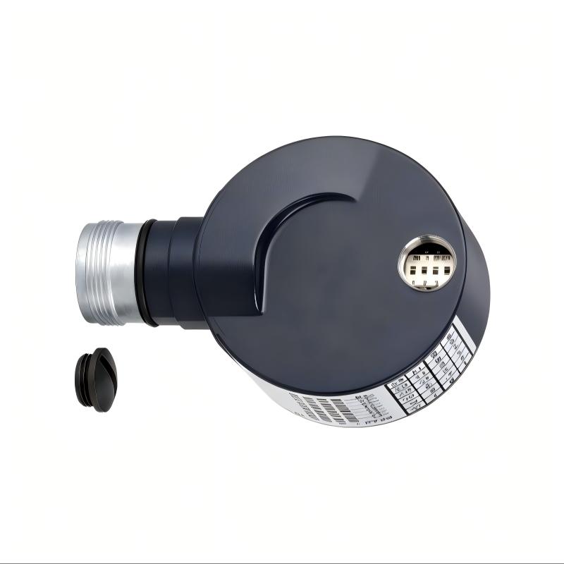
The encoder uses a radial 12-pin M23 male connector for electrical connection. Its housing is made of Zamak, while the base is aluminium and the shaft is stainless steel. With an IP65 protection rating, the unit is designed for industrial environments where protection against dust and water jets is required under the specified test conditions.
For maintenance teams, system integrators, and industrial spare-parts buyers, the XCC-1510PSM05Y is a component to consider when maintaining compatible Schneider Electric OsiSense XCC encoder installations or sourcing replacement feedback devices. Before ordering, buyers should verify the exact model reference, configured resolution, output type, shaft dimensions, connector arrangement, and electrical compatibility with the existing equipment.
2. Technical Specifications
| Parameter | Specification |
|---|---|
| Manufacturer | Schneider Electric |
| Product family | OsiSense XCC |
| Model | XCC-1510PSM05Y |
| Product type | Incremental rotary encoder |
| Housing diameter | 58 mm |
| Shaft type | Solid shaft |
| Shaft diameter | 10 mm |
| Resolution | Parameterizable from 500 to 8,000 points |
| Output stage | Type Y push-pull |
| Rated supply voltage | 5–30 V DC |
| Electrical connection | Radial M23 male connector |
| Connector configuration | 12 pins |
| Maximum rotational speed | 9,000 rpm |
| Output frequency | Up to 300 kHz |
| Number of channels | 3 |
| No-load current consumption | 0–75 mA |
| Maximum output current | 40 mA |
| Enclosure material | Zamak |
| Base material | Aluminium |
| Shaft material | Stainless steel |
| Bearing type | 6000ZZ1 |
| Protection rating | IP65 |
| Operating temperature | -30°C to +100°C |
| Storage temperature | -30°C to +85°C |
| Weight | 0.465 kg |
Specifications should be checked against the exact product documentation and configured version before installation. The 500–8,000-point resolution range does not mean every unit is automatically set to a particular resolution when delivered.
3. Function and Working Principle
3.1 Converting Rotation into Digital Feedback
The primary function of the XCC-1510PSM05Y is to convert mechanical rotation into electrical pulse signals. When a machine shaft rotates, the encoder detects the movement and generates a corresponding sequence of output signals.
A PLC, motion controller, counter module, or other compatible receiving device can process these signals to determine how far the shaft has rotated and how quickly it is moving. The control system can then use the feedback for monitoring, sequencing, synchronization, or position-related calculations.
Unlike an absolute encoder, which reports an encoded position value within its defined range, an incremental encoder generally reports movement through changes in its output signals. The receiving controller must count these signals and establish a reference position when the application requires a meaningful absolute machine coordinate.
3.2 Parameterizable Resolution
The XCC-1510PSM05Y supports a configurable resolution range of 500 to 8,000 points. Resolution affects how finely rotational movement can be represented by the encoder’s output.
For example, a higher configured resolution can provide more measurement increments for each revolution. This may be useful when an application needs finer speed observation or more detailed relative movement feedback. A lower resolution may be sufficient for applications where the controller does not require as many increments per revolution.
The appropriate setting depends on the application, controller input capability, mechanical transmission ratio, and maximum operating speed. Higher resolution also increases the number of pulses that the control system must process, so the encoder configuration and the receiving electronics must be considered together.
When replacing an existing unit, confirm the actual configured resolution rather than relying only on the model’s supported range.
3.3 Type Y Push-Pull Output
The Type Y output stage uses a push-pull electrical output arrangement. This output type can actively drive the output signal toward both logic levels, subject to the encoder’s specified electrical limits.
The receiving input must be compatible with the encoder’s output characteristics and supply voltage. Before connection, check the controller’s input circuit, voltage thresholds, common-reference arrangement, maximum counting frequency, and wiring requirements.
The maximum output current is specified as 40 mA. This figure should not be interpreted as a recommendation to operate every receiving input at that current. Actual loading must remain within the product’s electrical specifications.
3.4 Three-Channel Feedback
The encoder is specified with three channels. The available channel signals can support rotational feedback and associated reference or monitoring functions, depending on the wiring and receiving-system configuration.
The control system must be configured to interpret the connected channels correctly. Incorrect channel mapping, unsuitable input settings, or poor electrical connections may lead to missed counts, inconsistent speed readings, or incorrect movement calculations.
3.5 Supply Voltage and Electrical Protection
The XCC-1510PSM05Y operates from a 5–30 V DC supply. This broad supply range can simplify integration into different low-voltage industrial control architectures, provided the selected voltage is permitted by both the encoder and the connected equipment.
The product documentation specifies protection against reverse polarity and short circuits. These features offer additional electrical protection, but they do not eliminate the need for correct wiring, suitable overcurrent protection, proper grounding practices, and compliance with the installation requirements.
4. Role in Industrial Control Systems
4.1 PLC-Based Automation
In a PLC-controlled machine, an incremental encoder can provide movement feedback to high-speed counter inputs, dedicated encoder interfaces, or other compatible counting hardware.
The PLC uses the received pulse information to monitor rotational speed, track relative movement, and support machine sequences. The suitability of a particular PLC input depends on its electrical interface, maximum counting rate, supported signal type, and configuration.
The XCC-1510PSM05Y can be considered for such applications when the control hardware is compatible with its Type Y push-pull output and the selected resolution.
4.2 Motor and Drive Monitoring
Rotational feedback is useful in applications involving motors, gearboxes, rollers, and rotating machine components. An encoder may help a control system observe speed changes or compare movement against an expected operating condition.
However, the XCC-1510PSM05Y should not automatically be treated as a universal closed-loop servo feedback device. Suitability for a particular drive or motor depends on the drive’s supported feedback interface, signal format, electrical requirements, and control architecture.
4.3 Position and Length Measurement
Incremental encoders are frequently used to estimate linear movement when connected to a rotating roller, measuring wheel, or transmission mechanism. The controller converts the counted rotational increments into a distance value using the mechanical dimensions and transmission ratio.
Measurement accuracy depends on more than encoder resolution. Wheel diameter, mechanical slip, shaft alignment, backlash, signal integrity, and controller processing can all affect the final result.
4.4 Machine Condition Monitoring
Changes in measured speed or movement patterns may help operators identify deviations from expected machine operation. When combined with appropriate PLC logic, alarms, and maintenance procedures, encoder feedback can contribute to equipment monitoring.
The encoder itself does not diagnose every mechanical fault. Its value lies in providing movement information that the wider control system can interpret alongside other measurements and operating conditions.
5. Industrial Applications
5.1 Packaging Machinery
Packaging lines often use rotary feedback to coordinate rollers, conveyors, indexing mechanisms, and product handling equipment. An encoder can provide movement information that helps the controller maintain repeatable sequences.
For a packaging machine, the configured resolution should be selected in relation to conveyor speed, required measurement detail, and the maximum counting capability of the controller.
5.2 Conveyor Systems
Conveyor systems may use an incremental encoder to measure roller rotation or estimate belt movement. The resulting feedback can support speed monitoring, product spacing, synchronization, and length calculations.
The encoder must be mechanically coupled to the intended rotating component. Slippage between the conveyor belt and the measurement roller can create errors even when the encoder is operating correctly.
5.3 Material Handling Equipment
Automated material handling systems rely on predictable movement to transfer products between processing stages. Encoder feedback can support relative movement monitoring and coordinated machine sequences.
The XCC-1510PSM05Y may be suitable where its shaft arrangement, electrical output, environmental rating, and resolution match the equipment design.
5.4 Printing and Converting Machines
Printing, labeling, winding, and converting equipment can use rotational feedback to monitor rollers and support synchronized movement. Encoder signals may be used by a controller to track relative motion or coordinate machine operations.
Applications with rapid speed changes should account for maximum rotational speed, output frequency, and the processing capability of the receiving system.
5.5 Textile and Paper Processing
Textile production and paper processing can involve continuous material movement and rotating equipment. Incremental feedback may help monitor roller speed and estimate material travel.
Installation quality is important in these applications because vibration, shaft misalignment, and contamination around mechanical interfaces may affect long-term reliability.
5.6 General Industrial Machinery
The encoder may also be considered for compatible assembly machines, winding systems, inspection equipment, and automated production stations. In every case, the application must be evaluated against the exact encoder specifications rather than selecting the component by housing diameter alone.
6. Installation and System Integration
6.1 Verify Mechanical Compatibility
The XCC-1510PSM05Y uses a 10 mm solid shaft and a 58 mm housing. Confirm that the coupling, mounting arrangement, available installation space, and shaft alignment match the machine.
Do not confuse this model with an XCC encoder that uses a through shaft. Solid-shaft and through-shaft versions require different mechanical arrangements and are not automatically interchangeable.
Avoid applying excessive radial or axial force during installation. The connected shaft and coupling should be aligned correctly to reduce unnecessary loading on the encoder bearings.
6.2 Confirm the Electrical Interface
Before wiring, verify the supply voltage and the input compatibility of the receiving controller. The Type Y push-pull output must be connected to an interface designed to accept its signal characteristics.
Use the correct pin assignment from the applicable product documentation. Do not assume that a connector with the same physical size uses the same pinout as another encoder.
The radial M23 male connector has 12 pins. The mating connector, cable, and wiring arrangement must be suitable for the installed system and its environmental conditions.
6.3 Configure the Required Resolution
Because the model belongs to a parameterizable version of the XCC family, confirm the resolution setting required by the application and how the selected version is configured.
The controller program, counter scaling, and any movement calculations must agree with the encoder’s actual resolution. If a replacement encoder is configured differently from the original unit, the machine may report an incorrect speed or travel distance unless the associated settings are updated.
6.4 Check Maximum Speed and Counting Frequency
The documented maximum rotational speed is 9,000 rpm, while the output frequency is specified up to 300 kHz. Both limits matter when evaluating the application.
The effective pulse rate depends on the configured resolution and rotational speed. The encoder’s permitted operating limits and the controller’s input capability must both be respected. Do not assume that every resolution setting can be used at the maximum rotational speed without checking the detailed operating conditions.
6.5 Protect the Installation Environment
The IP65 rating indicates protection against dust ingress and water jets under the specified test conditions. It does not mean the encoder is suitable for immersion or every chemical, washdown, or outdoor exposure scenario.
Check the operating temperature range of -30°C to +100°C, protect the connector interface, and route cables away from excessive heat, moving machinery, and potential sources of electrical interference.
6.6 Commissioning Checks
After installation, verify that the encoder produces stable signals while the shaft rotates. Compare the controller’s speed or movement reading with a known reference when practical.
If the count is unstable, inspect the mechanical coupling, supply voltage, connector seating, wiring, electrical noise, and input configuration. Confirm that the selected resolution and controller scaling match the actual encoder setup.
7. Compatible System Components
The following table identifies the main component categories typically considered when integrating an incremental encoder. It is not a guarantee of direct compatibility with every product in a category.
| Component | Role in the System | Compatibility Considerations |
|---|---|---|
| PLC or automation controller | Processes encoder feedback and runs machine logic | Must support the required input interface and counting rate |
| High-speed counter module | Counts rapid pulse signals | Check push-pull input compatibility and maximum frequency |
| Encoder interface module | Receives and interprets encoder channels | Confirm voltage, channel, and signal requirements |
| DC power supply | Provides encoder operating voltage | Must provide a suitable voltage within 5–30 V DC |
| M23 mating connector | Connects the encoder to field wiring | Verify 12-pin configuration and correct pin assignment |
| Industrial control cable | Carries supply and output signals | Select suitable conductors, shielding, routing, and environmental protection |
| Mechanical coupling | Connects the encoder shaft to the rotating mechanism | Must suit the 10 mm solid shaft and application geometry |
| Drive or motion controller | Coordinates movement and speed-related functions | Verify that its feedback interface supports this encoder type |
The final configuration should be validated against the controller and machine documentation. Physical connector compatibility alone is insufficient to establish electrical or functional compatibility.
8. Recommended Alternatives and Replacement Considerations
When sourcing an alternative, begin by identifying the required shaft type, shaft diameter, resolution, output stage, supply voltage, connector, and mechanical mounting arrangement.
| Model or Product Category | Main Difference | Replacement Consideration |
|---|---|---|
| Schneider XCC-1510PS05Y | Fixed 500-point version; 10 mm solid shaft | Check the fixed-resolution specification and the required controller scaling |
| Schneider XCC-1510PS10Y | Fixed 1,000-point version; 10 mm solid shaft | Consider only if 1,000 points per revolution suits the application |
| Schneider XCC-1510PS25Y | Fixed 2,500-point version; 10 mm solid shaft | Verify the required resolution and maximum pulse rate |
| Schneider XCC-1510PSM02Y | Parameterizable version with a different resolution range | Confirm the actual configurable range and required setup |
| Schneider XCC-1514TS family | Through-shaft design with a different shaft arrangement | Not a direct mechanical substitute for the 10 mm solid-shaft model |
| Compatible third-party incremental encoder | May use a different electrical interface or mounting design | Validate output type, voltage, resolution, connector, dimensions, and controller support |
These alternatives are starting points for engineering evaluation, not automatic drop-in replacements. Model availability and product status may vary. Before purchasing, compare the full part number and the applicable datasheet, particularly where the encoder is part of an existing machine with established wiring and PLC logic.
9. Key Advantages of the Schneider XCC-1510PSM05Y
Flexible Resolution Configuration
The documented 500–8,000-point range allows the encoder to be configured for different feedback requirements within its supported limits. This can be useful for machine designs that require a balance between measurement detail and signal-processing capacity.
Broad DC Supply Range
The 5–30 V DC operating range supports integration into a variety of compatible low-voltage control systems. The selected supply voltage must still meet the requirements of the complete installation.
Push-Pull Output
The Type Y push-pull output provides an actively driven output stage for compatible receiving electronics. Correct input matching and wiring remain essential for dependable signal transmission.
Industrial Mechanical Construction
The combination of a Zamak enclosure, aluminium base, and stainless steel shaft provides a construction intended for industrial use. Mechanical alignment and correct mounting remain important for service life.
IP65 Protection
The IP65 rating offers protection against dust and water jets under specified conditions. This can be valuable in production environments where the encoder may encounter airborne dust or occasional water exposure.
Standardized M23 Connection
The radial 12-pin M23 male connector provides a defined electrical interface. Buyers should verify the mating connector and pinout to avoid wiring errors during installation or replacement.
Compact, Clearly Defined Form Factor
The 58 mm housing diameter and 10 mm solid shaft provide key mechanical reference dimensions for equipment designers and maintenance engineers evaluating the encoder for an existing assembly.
10. Technical FAQs
Q1: What is the Schneider XCC-1510PSM05Y?
It is an OsiSense XCC incremental rotary encoder designed to convert rotational movement into electrical pulse signals for compatible industrial automation and motion-feedback applications.
Q2: What is the housing diameter?
The housing diameter is 58 mm.
Q3: What shaft does this encoder use?
It uses a 10 mm solid shaft. It should not be confused with through-shaft encoder models in the XCC family.
Q4: What is the encoder’s resolution?
The XCC-1510PSM05Y is a parameterizable model with a documented resolution range of 500 to 8,000 points. The actual configuration should be verified for the unit being installed or purchased.
Q5: What is the output type?
It uses a Type Y push-pull output stage. The receiving controller or interface must support the output’s electrical characteristics.
Q6: What supply voltage is required?
The specified supply range is 5–30 V DC. Select a voltage suitable for the complete electrical interface and follow the applicable wiring documentation.
Q7: What connector does it use?
It has a radial M23 male connector with 12 pins. Confirm the mating connector and pin assignment before connecting the encoder.
Q8: What is the maximum rotational speed?
The documented maximum rotational speed is 9,000 rpm. The allowable operating point must also respect the output-frequency limit and the capabilities of the receiving electronics.
Q9: Is the encoder suitable for dusty industrial environments?
Its IP65 rating indicates protection against dust ingress and water jets under specified conditions. Suitability for a particular environment depends on exposure, installation, connector sealing, and maintenance practices.
Q10: Can it be connected directly to any PLC?
No. The PLC or input module must be compatible with the encoder’s supply range, Type Y push-pull signals, channel configuration, and maximum pulse frequency. A suitable high-speed counter or interface may be required.
Q11: Can it replace a 14 mm through-shaft encoder?
Not automatically. The XCC-1510PSM05Y has a 10 mm solid shaft, while a through-shaft model has a different mounting arrangement. A replacement must meet both the mechanical and electrical requirements of the application.
Q12: What should buyers verify before ordering?
Confirm the complete model number, housing diameter, shaft type and diameter, required resolution, output stage, supply voltage, connector, weight, product condition, and compatibility with the existing control system.
11. Procurement and Maintenance Recommendations
For industrial spare-parts procurement, correct identification is essential. The XCC-1510PSM05Y has a similar naming structure to other XCC encoders, but small differences in the model suffix can indicate a different resolution, output stage, or shaft arrangement.
Before placing an order, compare the part number on the installed unit with the required part number in the machine documentation. Where the encoder is parameterizable, verify the intended resolution and any setup requirements. If the application is safety-critical or tightly synchronized, carry out an engineering review before approving a substitute.
During maintenance, inspect the shaft coupling, mounting hardware, connector condition, and cable routing. Investigate intermittent counts or unstable readings before assuming that the encoder itself has failed. Mechanical misalignment, electrical interference, loose connections, incorrect scaling, or unsuitable input hardware may produce similar symptoms.
When installing a replacement, confirm that the controller’s counting configuration and engineering-unit conversion match the installed encoder. Following replacement, test the machine at representative speeds and operating conditions, and verify the feedback against a known reference where feasible.
For long-term inventory management, record the complete part number, actual configured resolution, machine location, installation date, and relevant commissioning settings. These records can reduce downtime and help purchasing teams identify the correct replacement more efficiently.
12. Conclusion
The Schneider Electric XCC-1510PSM05Y is a parameterizable incremental encoder from the OsiSense XCC family, featuring a 58 mm housing, 10 mm solid shaft, Type Y push-pull output, 5–30 V DC supply, and radial 12-pin M23 male connector. Its documented resolution range of 500 to 8,000 points makes it a candidate for compatible industrial movement measurement, rotational monitoring, and automation feedback applications.
For reliable operation, the encoder must be matched to the receiving controller, configured for the required resolution, and installed with appropriate mechanical alignment and electrical protection. Buyers and maintenance teams should verify the complete model reference and application requirements before treating it as a replacement for another encoder.
When the mechanical dimensions, output interface, resolution, and operating conditions match the application, the XCC-1510PSM05Y can provide useful rotational feedback for industrial automation equipment and ongoing maintenance needs.