

ProductPRODUCT
Featured products
Contact Us
- Schneider
- XCC-1506PS25Y
- XCC Incremental Encoder
- France
- 58 mm
- 0.495 kg
- Xiamen, China
- New & In Stock
- T/T, PayPal, Western Union
- 1 Year
- 1-3 Working Days
- DHL, UPS, TNT, FedEx and EMS.
- 24-Hour Service
- COO
- 9
Our advantage

Global Logistics
We have a 10-year logistics and express cooperation agreement, so our products can be shipped to any place in the world.

Brand new and original
Our products are imported in bulk from the place of origin. Because of the cooperative relationship, our products are all original and 100% new.

24-hour service
We provide 7*24 hours service to our customers. We will be there whenever you need us.

Price advantage
All our products are priced very favorably because we have our own warehouse and supply.
| Company Information | |||
| [email protected] | |||
| Mobile | +8615980777398 | ||
| +8615980777398 | |||
| 15980777398 |
1. Product Overview
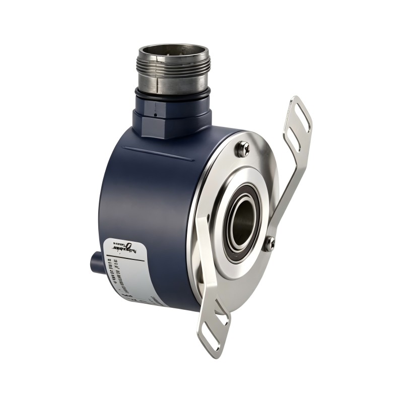
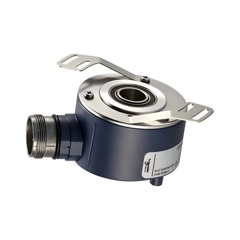
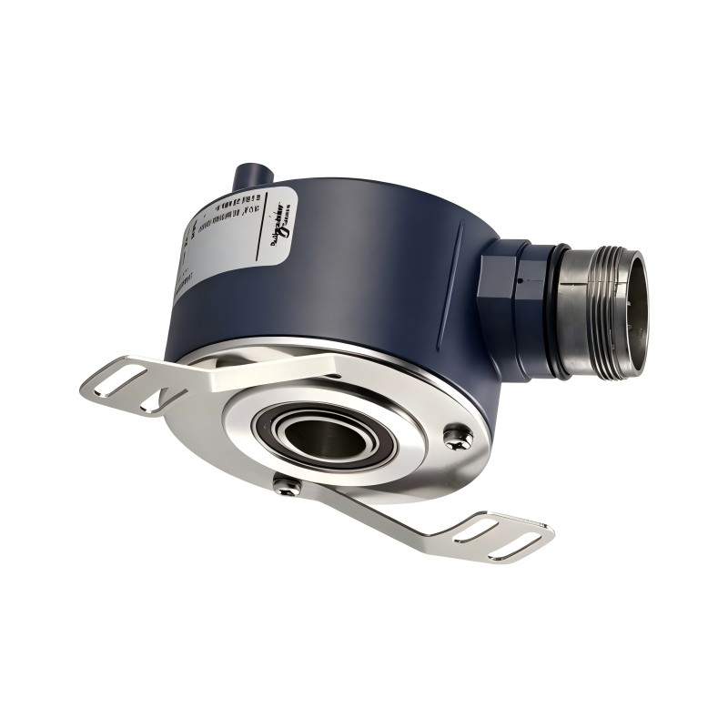
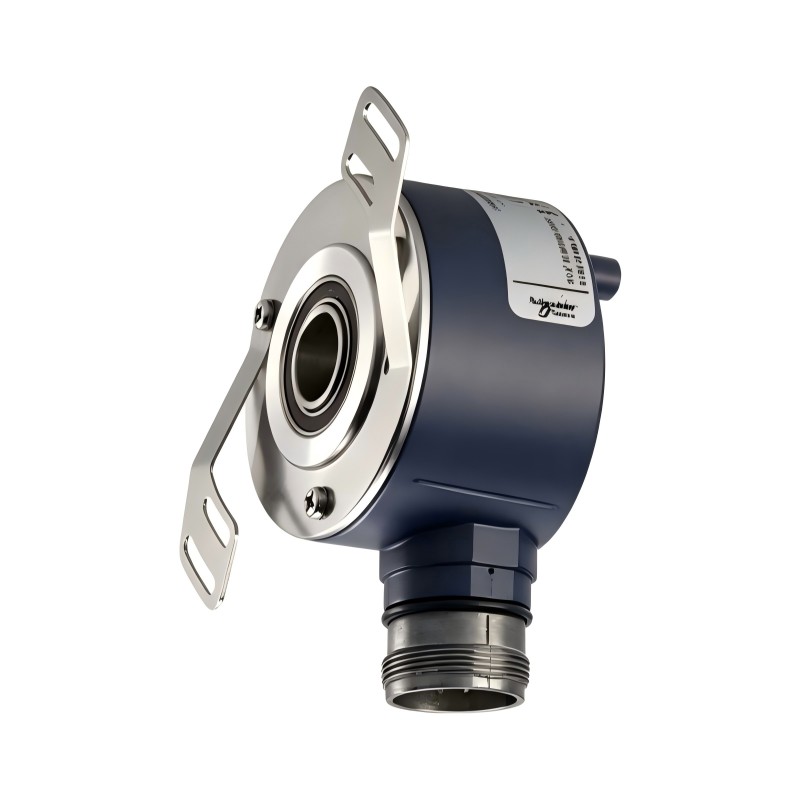
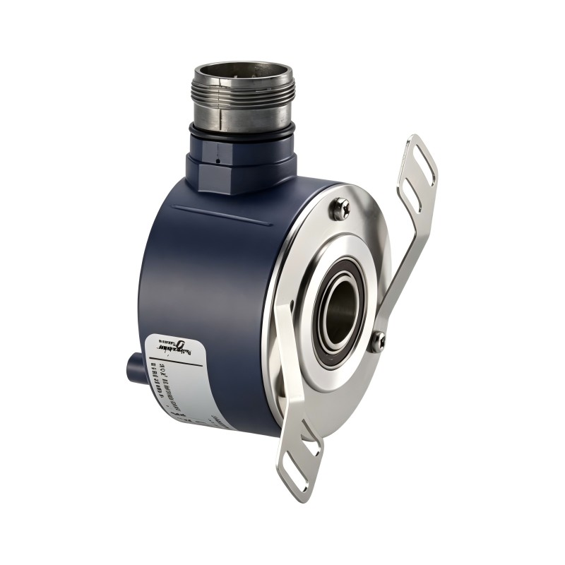
The Schneider Electric XCC1506PS25Y is an incremental rotary encoder designed for industrial automation, motion monitoring, and rotational measurement applications. Part of the OsiSense XCC product family, this encoder converts mechanical rotation into electrical pulse signals that can be processed by compatible programmable logic controllers (PLCs), counters, motion controllers, and other automation equipment.
The XCC1506PS25Y features a 58 mm housing, a 6 mm solid shaft, and a resolution of 2500 points per revolution. Its Type Y push-pull output stage supports integration into control systems designed for compatible push-pull encoder signals. The encoder uses a radial 12-pin M23 male connector and operates with a 5–30 V DC supply.
Incremental encoders are commonly used when a machine needs to monitor shaft rotation, calculate rotational speed, measure relative movement, or coordinate mechanical operations. In a properly configured control system, the XCC1506PS25Y can provide feedback for conveyors, packaging machinery, automated assembly equipment, printing systems, and other industrial machines.
The encoder’s solid-shaft design is suitable for installations using a compatible coupling and mounting arrangement. Its mechanical dimensions, output interface, resolution, and operating environment should all be considered when selecting the device for a new machine or replacing an existing encoder.
For maintenance teams and industrial spare-parts buyers, verifying the complete model number is especially important. The XCC1506PS25Y should not automatically be treated as interchangeable with other XCC models that have different resolutions, shaft dimensions, or output stages.
2. Technical Specifications
| Parameter | Specification |
|---|---|
| Brand | Schneider Electric |
| Product family | OsiSense XCC |
| Model | XCC1506PS25Y |
| Product type | Incremental rotary encoder |
| Housing diameter | 58 mm |
| Shaft type | Solid shaft |
| Shaft diameter | 6 mm |
| Shaft tolerance | G7 |
| Resolution | 2500 points per revolution |
| Output stage | Type Y |
| Output type | Push-pull |
| Supply voltage | 5–30 V DC |
| Electrical connection | Radial M23 male connector, 12 pins |
| Number of output channels | 3 |
| Maximum output frequency | 300 kHz |
| Maximum rotational speed | 9000 rpm |
| Maximum radial load | 10 daN |
| Maximum axial load | 5 daN |
| Enclosure material | Zamak |
| Base material | Aluminium |
| Shaft material | Stainless steel |
| Protection rating | IP65 |
| Operating temperature | -30°C to +100°C |
| Product weight | 0.495 kg |
Specifications should be verified against the applicable product documentation before installation. Confirm the electrical characteristics, pin assignments, mechanical loading limits, and controller compatibility for the exact unit being supplied.
3. Function and Working Principle
The primary function of the XCC1506PS25Y is to convert shaft rotation into electrical signals that represent relative movement. A compatible control device reads these signals and uses them to calculate rotational position, speed, direction, or movement increments.
Incremental Position Measurement
An incremental encoder generates pulses as its shaft rotates. The receiving controller counts the pulses to determine how far the shaft has moved relative to a reference position.
The XCC1506PS25Y provides 2500 points per revolution. This resolution establishes the nominal number of encoder points associated with one complete shaft revolution. The final count resolution depends on the receiver’s decoding method and configuration.
Unlike an absolute encoder, an incremental encoder does not independently retain a unique absolute shaft position after power is removed. Depending on the application, a machine may need a homing routine, reference sensor, or another position-establishing procedure before absolute machine coordinates can be used.
Rotational Speed Measurement
The encoder produces pulses at a frequency related to shaft speed. A compatible high-speed counter, PLC, or motion controller can measure the pulse frequency and calculate rotational speed.
This feedback can be used to monitor whether a rotating mechanism is operating within its expected speed range. It can also support speed comparison, production monitoring, and synchronization between machine sections.
The encoder supplies feedback rather than directly controlling the motor. Any speed regulation or corrective action must be performed by the connected controller and drive system.
Direction Detection
Incremental encoder systems commonly use phase-related signals to determine the direction of rotation. A compatible receiving device can compare the timing relationship between the relevant channels to identify forward and reverse movement.
The XCC1506PS25Y has three output channels listed in its specifications. The actual channel assignments and required wiring should be confirmed using the model-specific connection diagram before commissioning.
Push-Pull Signal Output
The Type Y output stage uses a push-pull interface. This type of output can actively drive the signal both high and low, allowing it to work with compatible receiving circuits.
The receiving device must support the encoder’s output characteristics, voltage levels, input current, and signal frequency. A controller designed for RS-422 differential signals may require a different encoder interface or a properly engineered signal-conversion arrangement.
Correct wiring, appropriate cable routing, and suitable shielding are important for stable operation, particularly when the encoder is installed near motor drives, contactors, or other sources of electrical interference.
4. Role in Industrial Control Systems
The XCC1506PS25Y normally operates as one component within a larger automation system. It provides motion-related signals that other equipment uses to monitor and coordinate machine operation.
PLC Integration
A PLC with a compatible high-speed counter or encoder input can process the encoder’s pulse signals. Depending on the controller’s functions and the machine program, these values may be used for speed measurement, movement tracking, production counting, and sequence control.
Before integration, engineers should confirm that the PLC input supports the encoder’s push-pull output and the expected pulse frequency. Standard digital inputs are not always suitable for high-speed encoder signals.
Motor and Drive Monitoring
When used with a compatible drive or motion controller, encoder feedback can help monitor the rotation of a motor-driven mechanism. The control system may compare measured movement against a target value and use the result for monitoring or motion control.
Direct feedback control depends on the capabilities of the drive and controller. The encoder’s output stage and signal characteristics must match the receiving interface.
Position and Travel Measurement
When mechanically coupled to a rotating shaft or roller, the encoder can provide incremental movement information. A controller can translate pulse counts into angular displacement or linear travel when the machine’s mechanical dimensions and transmission ratios are known.
For example, a conveyor application may use encoder feedback to estimate belt movement. Accurate conversion requires consideration of roller circumference, gearing, mechanical slip, and the configured counting method.
Machine Diagnostics
Encoder feedback can help maintenance personnel identify irregular movement or unexpected speed changes. If the controller detects missing pulses, unstable counts, or a difference between expected and measured movement, technicians can investigate the encoder, cabling, coupling, mechanical transmission, and receiving device.
These symptoms do not necessarily mean the encoder itself has failed. Systematic troubleshooting helps distinguish electrical faults from mechanical or configuration problems.
5. Industrial Applications
Conveyor Systems
Conveyors use rotational feedback to monitor drive rollers, track movement, and coordinate product transportation. The XCC1506PS25Y can be considered for installations where its solid-shaft configuration, resolution, and electrical interface meet the machine requirements.
When connected to a suitable controller, its pulse signals can support speed estimation, distance calculations, and movement monitoring.
Packaging Machinery
Packaging equipment often requires coordinated movement between conveyors, rollers, feeders, and other driven mechanisms. Incremental encoder feedback can help the control system track movement and synchronize machine operations.
The appropriate resolution depends on the required positioning performance, mechanical transmission, and controller configuration.
Printing and Web-Handling Equipment
Printing and continuous-processing systems may need to monitor roller rotation and coordinate material movement. Encoder feedback can help measure relative motion and support synchronization between driven sections.
Stable performance depends on proper mechanical coupling, suitable wiring, and compatibility between the encoder and receiving equipment.
Automated Assembly Lines
Assembly machinery may use encoder signals to track the rotation of shafts or driven components. A PLC or motion controller can use the feedback to confirm movement, count cycles, or trigger actions when a configured movement threshold is reached.
Cutting and Feeding Machines
Cutting, feeding, and material-processing systems often translate rotational motion into linear movement. An encoder can provide the pulse data needed to estimate feed distance or coordinate a sequence of machine operations.
The relationship between pulse count and actual material travel must be established from the mechanical design. Roller diameter, transmission ratios, slip, and controller decoding settings all affect the resulting measurement.
General Industrial Machinery
The encoder may also be considered for winding equipment, rotating tables, material-handling machinery, and other industrial systems that require incremental rotational feedback and have a compatible mounting arrangement.
The application should be evaluated against the encoder’s operating speed, output frequency, environmental conditions, and mechanical load limits.
6. Installation and System Integration
Correct installation helps maintain measurement reliability and reduces the likelihood of premature failure.
Mechanical Installation
The XCC1506PS25Y has a 58 mm housing and a 6 mm solid shaft. The shaft is normally connected to the machine through a compatible coupling.
Before installation:
- Confirm the shaft diameter and tolerance requirements.
- Check that the coupling matches the encoder shaft and machine shaft.
- Align the encoder and driven shaft correctly.
- Avoid applying excessive radial or axial force.
- Secure the encoder using the appropriate mounting hardware.
- Protect the encoder from shock, vibration, and mechanical interference.
- Confirm that the installation provides adequate clearance for the connector and cable.
Misalignment or excessive coupling force can damage bearings and affect measurement stability. Follow the specified mechanical limits rather than relying on the housing dimensions alone.
Electrical Connection
The encoder uses a radial M23 male connector with 12 pins. A compatible mating connector or cable assembly is required.
Before connecting the encoder, verify:
- The correct supply voltage.
- The signal output type and voltage characteristics.
- The exact connector pin assignments.
- The input requirements of the receiving device.
- The cable’s electrical and environmental suitability.
- Shielding and grounding arrangements.
- The maximum pulse frequency supported by the complete input circuit.
Do not assume that pin assignments or wire colors are identical across all XCC encoder variants. Use the correct connection diagram for the XCC1506PS25Y.
Controller Compatibility
The Type Y push-pull output must be compatible with the receiving PLC, high-speed counter, motion controller, or other interface.
A controller that accepts only RS-422 differential inputs may not be directly compatible. Likewise, a standard digital input may not be able to process the required pulse frequency.
If an interface converter is necessary, confirm that it supports the encoder’s signal levels, channel arrangement, and operating frequency.
Resolution and Scaling
The encoder provides 2500 points per revolution. The controller’s effective count resolution depends on its counting and decoding configuration.
For linear travel measurement, the program must also account for the mechanical relationship between encoder rotation and the moving component. This may include roller circumference, gear ratio, belt transmission, or screw lead.
Engineers should verify the count convention used by the controller and test the resulting scale against a known movement distance. This helps avoid errors caused by confusing encoder points with decoded counts.
Commissioning and Testing
After mechanical and electrical installation, rotate the shaft under controlled conditions and verify that the controller receives stable signals.
Check the direction of rotation, pulse count, speed calculation, and response to machine movement. If readings are unstable or missing, inspect the power supply, connector, cable, receiver configuration, and mechanical coupling before replacing the encoder.
7. Compatible System Components
The XCC1506PS25Y can be used with suitable industrial automation equipment. The following component categories may be required, depending on the system design.
| Component category | Purpose | Compatibility requirement |
|---|---|---|
| PLC | Processes feedback and executes machine logic | Must support the encoder signal format and required pulse frequency |
| High-speed counter | Counts encoder pulses | Must accept compatible push-pull signals |
| Motion controller | Processes motion feedback | Confirm supported encoder inputs and decoding methods |
| Motor drive | Controls the driven motor | Direct encoder connection depends on the drive’s feedback interface |
| M23 mating connector | Provides the electrical connection | Must match the 12-pin radial connector |
| Encoder cable | Transmits power and signal lines | Must suit the electrical characteristics and installation environment |
| Mechanical coupling | Connects the encoder shaft to the machine | Must fit the shaft dimensions and accommodate the installation |
| Mounting hardware | Secures the encoder to the machine | Must match the mechanical mounting arrangement |
| Industrial DC power supply | Supplies the encoder | Must meet the specified voltage and wiring requirements |
These are component categories rather than a guarantee of direct compatibility with every product. Check the relevant technical documentation before connecting the encoder to a specific PLC, drive, or interface module.
8. Recommended Alternative Models
Other XCC1506PS models may be considered when replacing an encoder or choosing a different resolution. Models with similar dimensions can still have different electrical characteristics.
| Model | Resolution | Output type | Key consideration |
|---|---|---|---|
| XCC1506PS01Y | 100 points/revolution | Push-pull | Lower resolution |
| XCC1506PS03Y | 360 points/revolution | Push-pull | Lower resolution |
| XCC1506PS05Y | 500 points/revolution | Push-pull | Lower resolution |
| XCC1506PS10Y | 1000 points/revolution | Push-pull | Same output type, lower resolution |
| XCC1506PS11Y | 1024 points/revolution | Push-pull | Different resolution |
| XCC1506PS25Y | 2500 points/revolution | Push-pull | Reference model |
| XCC1506PS50Y | 5000 points/revolution | Push-pull | Higher resolution; verify frequency and scaling |
| XCC1506PS25X | 2500 points/revolution | 5 V RS-422 differential | Different output interface; not automatically interchangeable |
Before selecting an alternative, verify the complete part number, shaft dimensions, resolution, output stage, supply requirements, connector pinout, and controller compatibility.
A higher-resolution encoder does not automatically improve the complete system’s accuracy. The controller, mechanical transmission, mounting quality, and signal-processing configuration must also support the intended measurement performance.
9. Key Advantages
2500-Point Resolution
The XCC1506PS25Y provides a defined resolution for incremental movement measurement. This can support rotational monitoring and motion feedback in applications that require more measurement points per revolution than lower-resolution models provide.
Push-Pull Output
Its Type Y push-pull output stage can interface with compatible industrial receiving circuits. Correct interface matching is important to ensure stable signal detection and reliable pulse counting.
Compact 58 mm Housing
The encoder’s 58 mm housing allows integration into machinery designed around the corresponding XCC mounting arrangement. The actual installation must still provide the required space for the body, shaft, mounting hardware, and connector.
Solid-Shaft Configuration
The 6 mm solid shaft supports installation with an appropriate coupling. This arrangement can be suitable for machinery where the encoder is mounted alongside a rotating shaft rather than directly around a through shaft.
Industrial Environmental Protection
The specified IP65 protection rating supports use in suitable industrial environments when the unit is installed correctly. The protection level of the complete installation also depends on the connector, mating components, cable routing, and sealing arrangement.
Application Flexibility
When paired with a compatible controller, the encoder can support speed measurement, incremental position tracking, movement counting, and process synchronization across a range of industrial machinery.
10. Technical FAQs
What is the Schneider XCC1506PS25Y?
It is an OsiSense XCC incremental rotary encoder designed to convert shaft rotation into electrical pulse signals. It has a 58 mm housing, a 6 mm solid shaft, and a nominal resolution of 2500 points per revolution.
What is the resolution of the XCC1506PS25Y?
Its resolution is 2500 points per revolution. The effective count resolution depends on the receiving controller’s decoding method and configuration.
What output type does this model use?
The XCC1506PS25Y uses a Type Y push-pull output stage. This differs from Type X models, which use a 5 V RS-422 differential output.
What is the operating voltage?
The specified supply range is 5–30 V DC. The receiving equipment must also be compatible with the encoder’s output signal characteristics.
Can it connect directly to a PLC?
It can connect to a PLC system if the PLC or its input module supports the encoder’s push-pull output, signal frequency, and wiring requirements. A suitable high-speed counter or encoder interface may be necessary.
What is the shaft diameter?
The encoder has a 6 mm solid shaft. Check the shaft tolerance and coupling requirements before installation.
What connector does it use?
It uses a radial M23 male connector with 12 pins. A compatible mating connector or cable assembly is needed, and the exact pin assignments should be checked against the product documentation.
What is the maximum rotational speed?
The published specification lists a maximum rotational speed of 9000 rpm. The application must also remain within the specified output-frequency and mechanical limits.
What is the protection rating?
The specified enclosure protection is IP65. Proper connector installation and suitable cable arrangements are important to maintain the intended protection.
What is the product weight?
The product weight is 0.495 kg. Shipping weight may differ depending on packaging and accessories.
Can the XCC1506PS25X replace the XCC1506PS25Y?
Not automatically. Both models have a nominal resolution of 2500 points per revolution, but the XCC1506PS25X uses a 5 V RS-422 differential output, while the XCC1506PS25Y uses a push-pull output. The receiving device must support the replacement model’s interface.
11. Procurement and Maintenance Recommendations
When purchasing the Schneider XCC1506PS25Y, verify the full model number rather than relying only on the XCC series designation. This helps prevent confusion between models with different resolutions or output interfaces.
For replacement projects, compare the existing encoder’s nameplate, wiring diagram, mechanical dimensions, and controller configuration with the proposed unit. Confirm that the 6 mm shaft and mounting arrangement are appropriate for the machine.
During maintenance, inspect the connector, cable, coupling, mounting hardware, and surrounding machinery. Unstable pulse signals can result from loose connections, electrical interference, excessive vibration, misalignment, or an unsuitable receiver configuration.
If an encoder has failed, investigate the underlying cause before installing a replacement. Correcting a mechanical overload, cable-routing problem, or input-interface mismatch can help prevent repeated failures.
For international spare-parts purchasing, confirm the product identification, condition, included accessories, packaging, and warranty terms with the supplier before placing an order.
12. Conclusion
The Schneider Electric XCC1506PS25Y is an incremental rotary encoder with a 58 mm housing, a 6 mm solid shaft, 2500 points per revolution, and a Type Y push-pull output stage. Its specified supply range is 5–30 V DC, and it uses a radial 12-pin M23 male connector. The product weight is 0.495 kg.
When integrated with a compatible PLC, high-speed counter, or motion controller, the encoder can provide feedback for rotational speed monitoring, incremental position measurement, movement counting, and machine synchronization.
For reliable operation, confirm the encoder’s mechanical fit, output interface, supply voltage, connector wiring, and resolution settings before installation. These checks are particularly important when selecting a replacement for an existing industrial automation system.