

ProductPRODUCT
Featured products
Contact Us
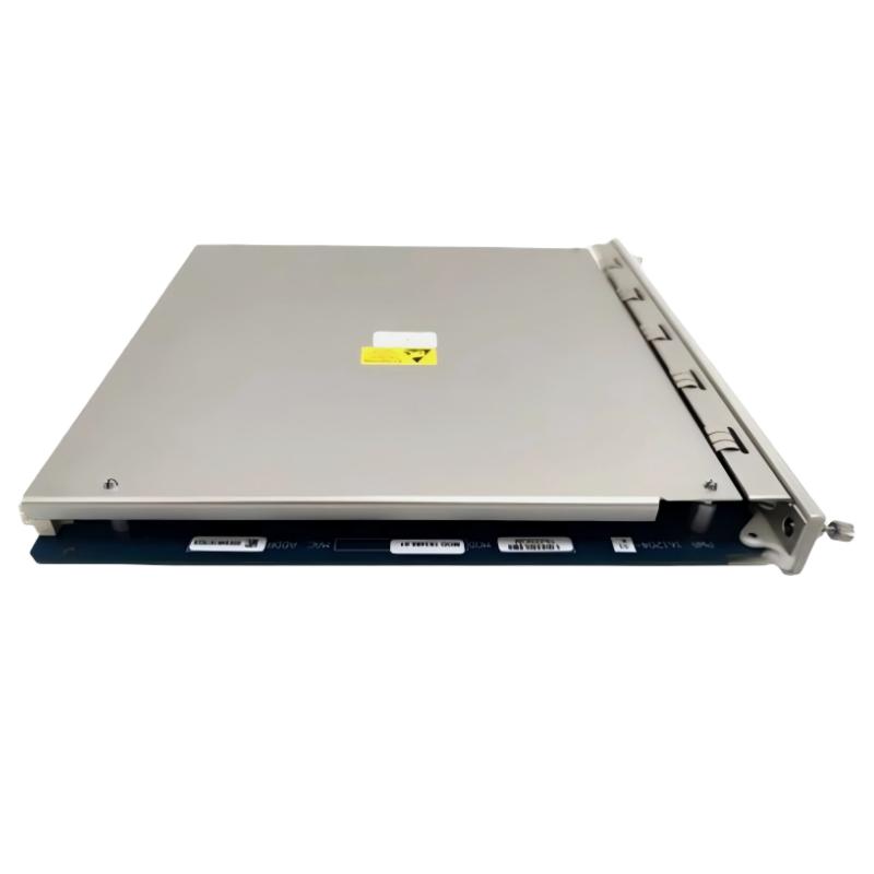
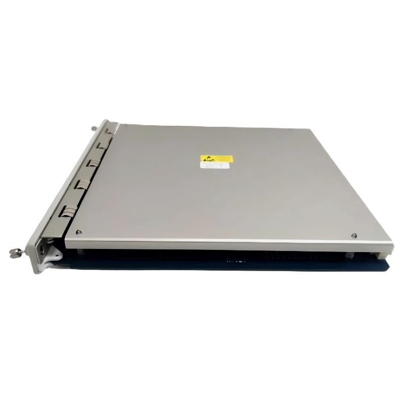
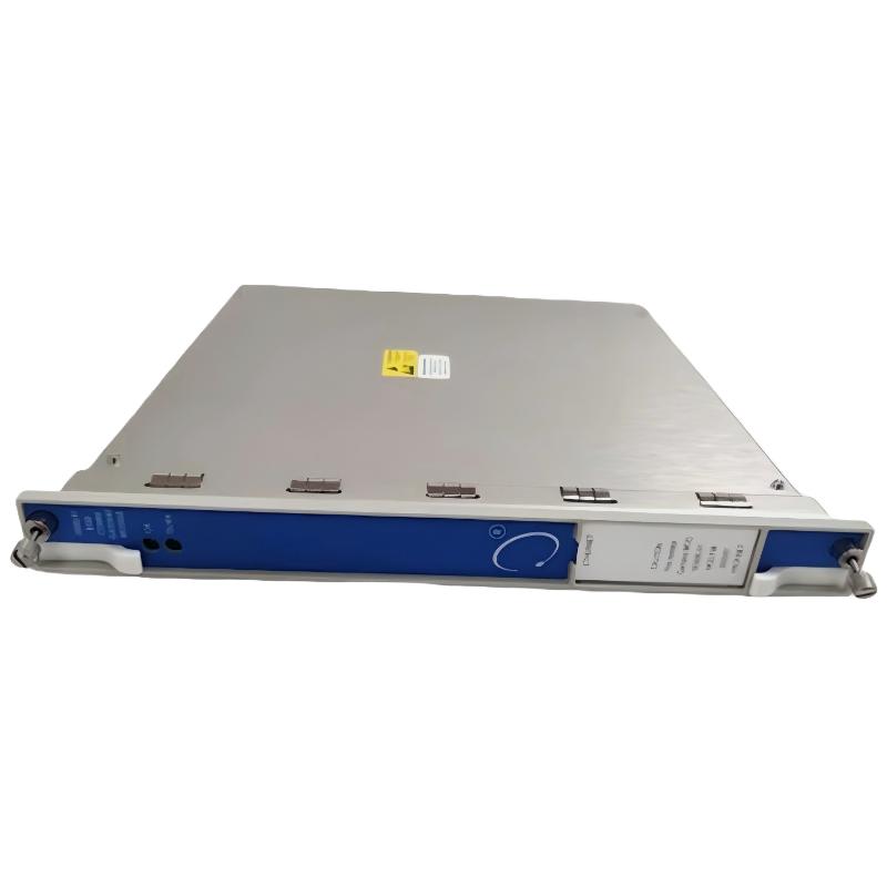
- Bently Nevada
- 3500/91-01-01-01
- Communication Gateway Module
- USA
- 241.3 × 24.4 × 241.8 mm
- 0.79kg
- Xiamen, China
- New & In Stock
- T/T, PayPal, Western Union
- 1 Year
- 1-3 Working Days
- DHL, UPS, TNT, FedEx and EMS.
- 24-Hour Service
- COO
- 5
Our advantage

Global Logistics
We have a 10-year logistics and express cooperation agreement, so our products can be shipped to any place in the world.

Brand new and original
Our products are imported in bulk from the place of origin. Because of the cooperative relationship, our products are all original and 100% new.

24-hour service
We provide 7*24 hours service to our customers. We will be there whenever you need us.

Price advantage
All our products are priced very favorably because we have our own warehouse and supply.
| Company Information | |||
| [email protected] | |||
| Mobile | +8615980777398 | ||
| +8615980777398 | |||
| 15980777398 |
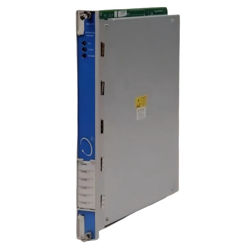
Bently Nevada 3500/91-01-01-01 — Technical Specifications, Product Overview, Applications, Advantages, and Recommended Models
1. Product Overview
The Bently Nevada 3500/91-01-01-01 is a model designation within the 3500 machinery protection and condition monitoring product family. The 3500 platform is designed to collect, process, and communicate information about industrial machinery operating conditions, helping plant personnel monitor equipment status and investigate abnormal operating behavior.
The 3500/91 product family is associated with Ethernet Global Data (EGD) communication gateway functionality. A gateway of this type serves as an interface between compatible machinery monitoring equipment and external industrial control or monitoring systems.
Unlike a vibration monitor or temperature monitor, a communication gateway does not directly acquire those physical measurements from a sensor. Instead, it makes supported information available to compatible external systems, subject to the installed hardware, communication protocol, and configuration.
The full ordering designation 3500/91-01-01-01 should be retained when identifying the product for purchasing, replacement, or engineering documentation. The exact meaning of the final configuration suffix must be checked against the applicable hardware specification; it should not be assumed to indicate a particular connector, protocol, or approval without verification.
This document provides a structured technical overview, a discussion of typical industrial applications and advantages, and ten related model recommendations. Where a configuration-specific specification cannot be established confidently, it is marked for verification rather than presented as a guaranteed value.
2. Brand, Product Series, and Model Identification
| Parameter | Technical specification |
|---|---|
| Brand | Bently Nevada |
| Product series | 3500 Machinery Protection System |
| Product family | Machinery Monitoring and Communication |
| Model | 3500/91-01-01-01 |
| Product name | EGD Communication Gateway Module |
| Primary function | Transfers selected monitoring values and status information from a compatible 3500 rack to external control systems |
| Communication protocol | Ethernet Global Data (EGD), Version 2.01 |
| Transport protocol | Ethernet UDP/IP |
| Ethernet standard | IEEE 802.3 / IEEE 802.3u |
| Ethernet data rates | 10 Mbps and 100 Mbps |
| Ethernet interface option | 10BASE-T / 100BASE-TX twisted-pair Ethernet |
| Connector | RJ-45 for the applicable copper Ethernet I/O configuration |
| Power source | Compatible 3500 rack backplane |
| Typical power consumption | 7.4 W |
| Main module dimensions (H × W × D) | 241.3 × 24.4 × 241.8 mm |
| Main module weight (kg) | 0.79 kg |
| I/O module dimensions (H × W × D) | 241.3 × 24.4 × 99.1 mm |
| I/O module weight (kg) | 0.39 kg |
| Combined module weight (kg) | Approximately 1.18 kg |
| Operating temperature | -30°C to +65°C |
| Storage temperature | -40°C to +85°C |
| Relative humidity | Up to 95%, non-condensing |
| Front rack allocation | One full-height slot |
| Rear rack allocation | One full-height slot |
| Front-panel indicators | OK and TX/RX |
| Primary use | Machinery monitoring data integration with compatible control systems |
The principal technical characteristics above correspond to the 3500/91 EGD gateway family. The complete suffix identifies a specific hardware and approval configuration, so the exact connector and certification details should be checked against the product’s nameplate and applicable specification. The gateway’s documented communication protocols are EGD Version 2.01 and Ethernet UDP/IP; it should not be described as a native Modbus gateway without confirming a different product configuration.
2.1 Model Number Interpretation
The ordering code can be understood at a high level as follows.
| Code segment | General meaning |
|---|---|
| 3500 | Machinery protection and monitoring platform |
| 91 | EGD communication gateway module |
| First -01 | Gateway configuration option |
| Second -01 | Ethernet I/O configuration option |
| Final -01 | Agency-approval configuration option |
The suffix interpretation above follows the published 3500/91 ordering structure. The exact approval scope should be checked for the intended installation, particularly when the equipment is to be installed in a classified or hazardous location.
3. Detailed Technical Parameters
3.1 Main Module Specifications
| Parameter | Value | Engineering explanation |
|---|---|---|
| Model | 3500/91-01-01-01 | Complete requested ordering designation |
| Module type | EGD communication gateway | Provides communication between the 3500 rack and compatible external systems |
| Data source | Compatible rack-monitored values and status | Information originates from the installed monitoring modules |
| Data output | Selected data values and status information | Available data depends on the configured system |
| Protocol | EGD Version 2.01 | Ethernet Global Data communication |
| Network transport | UDP/IP | Ethernet-based data transmission |
| Ethernet standards | IEEE 802.3 and IEEE 802.3u | Applicable Ethernet physical and link standards |
| Ethernet speeds | 10 Mbps / 100 Mbps | Depends on the compatible interface and network configuration |
| Copper interface | 10BASE-T / 100BASE-TX | Twisted-pair Ethernet |
| Connector | RJ-45 | For the applicable copper Ethernet I/O module |
| Typical power consumption | 7.4 W | Gateway module consumption under specified operating conditions |
| Power input | 3500 rack backplane | Not a standalone 24 V DC controller |
| Operating temperature | -30°C to +65°C | Specified operating range |
| Storage temperature | -40°C to +85°C | Specified storage range |
| Humidity | 95%, non-condensing | Environmental limit under the applicable specification |
| Main module dimensions (H × W × D) | 241.3 × 24.4 × 241.8 mm | Main module only |
| Main module weight (kg) | 0.79 kg | Excludes the I/O module and accessories |
| I/O module dimensions (H × W × D) | 241.3 × 24.4 × 99.1 mm | Rear I/O module |
| I/O module weight (kg) | 0.39 kg | I/O module only |
| Combined module weight (kg) | 1.18 kg | Sum of the two individual module weights |
| Front rack requirement | One full-height slot | Main module position |
| Rear rack requirement | One full-height slot | Associated I/O module position |
| Status indication | OK LED | Indicates normal module operation when operating correctly |
| Communication indication | TX/RX LED | Indicates communication activity |
| Data update behavior | Configuration-dependent | Must meet the requirements of the external control system |
These physical and electrical specifications are based on the 3500/91 gateway data sheet. The combined weight is a calculated sum of the main module and I/O module; it excludes packaging, cabling, and any separately installed network accessories.
3.2 Supported Data Types
The gateway can transfer selected information from the 3500 rack. Its function is data communication, not independent sensor measurement.
| Data category | Description | Typical purpose |
|---|---|---|
| Rack data | Rack-level status information | Helps external systems identify the operating state of the monitoring rack |
| Module data | Status information for supported monitoring modules | Helps maintenance staff identify module conditions |
| Channel data | Status and values for configured measurement channels | Makes selected machine measurements available to external systems |
| Floating-point values | Numeric measurement values in supported data exchanges | Allows control systems to display and process measurements |
| Setpoints | Supported configured setpoint information | Helps external applications interpret measurement thresholds |
| Group reset | Supported reset command exchange | Allows compatible external systems to request a configured reset |
| Group trip multiply | Supported control exchange | Enables a compatible external system to request the configured function |
| Group alarm inhibit | Supported control exchange | Allows supported alarm-inhibit functions to be requested |
| Group special alarm inhibit | Supported control exchange | Supports the corresponding configured inhibit function |
The exact variables, commands, and data structures available to a particular installation depend on the gateway configuration and compatible external controller. The presence of a supported data category does not mean every rack value is automatically available without configuration.
3.3 Ethernet Communication Characteristics
| Parameter | Specification |
|---|---|
| Communication method | Ethernet Global Data |
| EGD version | 2.01 |
| Transport protocol | UDP/IP |
| Copper Ethernet | 10BASE-T / 100BASE-TX |
| Network standards | IEEE 802.3 / IEEE 802.3u |
| Copper connector | RJ-45 |
| Fiber option | A separate 100BASE-FX I/O configuration is available within the 3500/91 family |
| Typical communication purpose | Delivery of rack-monitored values and status information |
| Network configuration | Must be compatible with the external controller |
| Data mapping | Must be configured for the receiving system |
| Diagnostic indication | Front-panel OK and TX/RX indicators |
| Power requirement | Compatible 3500 rack backplane |
The 3500/91 family includes different I/O options. The fiber-optic option should not be assumed to be installed in the requested -01-01-01 configuration, which is associated with the copper Ethernet option.
4. Product Introduction and Operating Principle
4.1 What Is the 3500/91-01-01-01?
The 3500/91-01-01-01 is an EGD communication gateway module designed to transfer supported machinery monitoring information from a compatible 3500 rack to an external control system.
Industrial machinery protection systems collect data from monitoring modules connected to vibration probes, temperature sensors, speed sensors, and other measurement devices. That information is valuable to maintenance engineers, but plant operators may also need access to it through their existing control system.
The communication gateway provides a digital path between the monitoring rack and compatible external equipment. It allows selected values and status information to be made available without requiring every measurement to be independently wired to the plant control system.
For example, a compressor’s vibration level may be acquired by a vibration monitor, while the communication gateway makes the configured measurement available to an external controller. The gateway does not generate the vibration measurement itself; it transfers information produced by the monitoring system.
4.2 How the Product Works
Step 1 — Machinery measurement
Compatible sensors and monitoring modules acquire vibration, temperature, position, speed, and other measurements.
Step 2 — Data processing within the 3500 rack
The installed monitors process the signals and maintain their configured measurement values and status information.
Step 3 — Gateway communication
The 3500/91 transfers supported information using EGD over Ethernet UDP/IP.
Step 4 — External system integration
A compatible controller receives the configured data for display, processing, and operational monitoring.
This arrangement separates the measurement function from the communication function. The monitoring modules remain responsible for acquiring and processing physical measurements, while the gateway provides the external communication path.
4.3 Difference Between a Gateway and a Monitoring Module
A communication gateway and a measurement module perform different tasks.
| Comparison item | 3500/91 gateway | Measurement module |
|---|---|---|
| Primary function | Communicates supported rack data | Acquires and processes specified measurement signals |
| Direct sensor input | Not its principal function | Depends on the measurement module |
| Vibration measurement | Transfers supported values from the rack | Performed by an appropriate vibration monitor |
| Temperature measurement | Transfers supported values from the rack | Performed by an appropriate temperature monitor |
| Speed measurement | Transfers supported values from the rack | Performed by an appropriate speed monitor |
| Communication with external systems | Main function | Depends on the wider system architecture |
| Physical installation | Compatible 3500 rack | Compatible 3500 rack |
| Replacement criteria | Protocol, interface, configuration, and approval compatibility | Measurement function, sensor compatibility, and configuration |
This distinction is important when troubleshooting. If a sensor value is incorrect inside the monitoring rack, replacing the communication gateway may not solve the underlying problem.
4.4 Role in the Machinery Protection Architecture
The gateway is intended to complement the machinery protection system rather than replace it.
The monitoring modules acquire measurements and evaluate configured operating limits. The communication gateway makes supported information available to compatible external systems.
This arrangement can help operators review equipment status and integrate machinery information into broader plant operations while keeping the original monitoring functions within the rack.
The external control system must be configured correctly to interpret the received data. Communication alone does not guarantee that an external display, alarm, or control action will operate correctly.
5. Industrial Applications
5.1 Oil and Gas Facilities
Oil and gas installations use compressors, turbines, pumps, and other rotating equipment that may require continuous condition monitoring.
The 3500/91 can transfer supported monitoring data from compatible racks to external systems, allowing selected equipment values and status information to be incorporated into plant-level monitoring.
Typical applications include:
-
Gas compression stations.
-
Gas processing facilities.
-
Production and gathering installations.
-
Pipeline compressor stations.
-
Offshore and onshore machinery monitoring systems.
Its suitability depends on the installed 3500 hardware, network architecture, and the external controller’s compatibility with EGD.
5.2 Petrochemical and Chemical Plants
Petrochemical facilities may have several machinery monitoring racks distributed across different process areas.
The gateway can help centralize selected machinery data within compatible external systems. Operators can then review supported measurements alongside process variables and other plant information.
This can be useful when investigating machinery alarms, comparing equipment conditions, or reviewing operational trends.
5.3 Refinery Operations
Refineries rely on compressors, pumps, turbines, and other critical rotating equipment.
The 3500/91 can provide a communication path for selected measurements and status information from compatible machinery monitoring racks. This may support centralized displays and integration with the plant’s existing control architecture.
The gateway does not replace the individual monitors responsible for vibration, temperature, or position measurements.
5.4 Power Generation
Power generation facilities may use machinery protection systems to monitor turbines, generators, pumps, and auxiliary equipment.
Where the external controller supports the required communication method, the gateway can make selected monitoring information available for operational review.
The final configuration should be evaluated against the plant’s control system, communication requirements, and equipment protection architecture.
5.5 Industrial Manufacturing
Manufacturing facilities often operate many motors, pumps, fans, compressors, and other rotating machines.
Centralizing compatible monitoring data can help maintenance teams compare machine conditions and identify equipment requiring further investigation.
The gateway can be useful where a compatible 3500 system is already installed and selected data must be transferred to a wider plant monitoring environment.
5.6 Centralized Condition Monitoring
A facility may have several monitoring racks distributed across separate machine rooms or process units.
A communication gateway can provide a defined data interface for compatible systems, helping engineers consolidate selected values and status information.
The number of gateways required, network architecture, data update requirements, and external-controller compatibility should be established during system design.
6. Main Product Advantages
6.1 Direct Integration With Compatible EGD Controllers
The 3500/91 supports Ethernet Global Data Version 2.01, allowing integration with compatible controllers.
This is valuable when a plant’s existing control architecture already supports EGD and requires a direct communication path from the machinery monitoring rack.
6.2 Digital Transmission of Monitoring Data
Digital communication reduces the need to recreate every supported measurement as a separate hardwired signal.
This can simplify selected integration tasks and allow external systems to receive numeric values and status information through a defined data structure.
The actual reduction in wiring depends on the number of required variables and the existing plant architecture.
6.3 Industrial Ethernet Compatibility
The applicable copper Ethernet interface supports 10BASE-T and 100BASE-TX networking.
This provides compatibility with appropriate industrial Ethernet infrastructure, subject to network configuration and controller requirements.
The installed I/O module must match the intended physical connection. A fiber-optic connection requires the corresponding supported fiber I/O configuration.
6.4 Compact Rack-Based Design
The main gateway occupies one full-height front slot, with its corresponding I/O module installed in a rear slot.
This design allows the gateway to be incorporated into the existing compatible rack architecture rather than requiring an unrelated standalone computer or controller solely for data transfer.
6.5 Monitoring-System Status Visibility
The gateway can communicate supported measurement values and status information from the rack.
This can help maintenance staff review selected operating conditions and identify equipment requiring attention through an external system.
The usefulness of the information depends on correct data mapping and the external system’s display and alarm configuration.
6.6 Separation of Communication and Protection Functions
The gateway provides a communication path without replacing the rack’s normal monitoring and machinery protection functions.
This separation allows the communication layer to serve the external control system while the installed monitoring modules continue to perform their designated tasks.
The complete system must still be designed and validated according to the required protection architecture.
6.7 Support for Centralized Equipment Monitoring
When data from compatible racks is made available to a common external system, maintenance personnel may be able to compare equipment conditions from a central location.
This can help streamline routine monitoring and support investigations involving several machines or process areas.
6.8 Diagnostic Indicators
The OK and TX/RX indicators provide a convenient way to assess basic module and communication status.
They can help distinguish a module-status issue from an apparent communication problem, although more detailed diagnosis may be required to identify the underlying cause.
6.9 Compatibility With an Existing 3500 Installation
For facilities already using compatible 3500 monitoring equipment, the gateway provides a communication option within the same platform.
This can simplify system integration when the existing hardware, firmware, external controller, and protocol configuration are compatible.
It should not be assumed that every rack or controller supports every configuration without additional verification.
7. Five Related Models in the 3500 Series
The following five models are relevant when evaluating communication, rack integration, and related machinery monitoring requirements.
Physical dimensions and weights are included as requested. Where a precise model-specific figure has not been established, the table identifies it as requiring confirmation rather than substituting another model’s measurements.
| Model | Product type | Main technical parameters | Dimensions (H × W × D) | Weight (kg) |
|---|---|---|---|---|
| 3500/92 | Communication Gateway | Modbus communication via supported serial and Ethernet interfaces; data mapping depends on configuration | Confirm exact hardware revision | Confirm exact part number |
| 3500/22M | Transient Data Interface | Provides compatible rack communication and transient-data interface functions | Confirm exact hardware revision | Confirm exact part number |
| 3500/25 | Enhanced Keyphasor Module | Processes compatible rotational-reference signals | Confirm exact hardware revision | Confirm exact part number |
| 3500/32M | Four-Channel Relay Module | Four relay channels for configured alarm and control functions | Confirm exact hardware revision | Confirm exact part number |
| 3500/50M | Tachometer Module | Supports compatible rotational-speed measurements | Confirm exact hardware revision | Confirm exact part number |
The dimensions and weights of these related models must be checked independently. The 3500/91’s 241.3 × 24.4 × 241.8 mm main-module envelope and 0.79 kg mass should not automatically be assigned to other models.
7.1 3500/92 Communication Gateway
The 3500/92 is the most directly relevant alternative when the required function is communication between the 3500 rack and external systems.
Unlike the 3500/91, which is designed for EGD communication, the 3500/92 supports Modbus communication through compatible serial and Ethernet interfaces.
This makes it a useful candidate when the external system expects Modbus rather than EGD.
Recommended application: installations requiring compatible Modbus communication and appropriate data mapping.
7.2 3500/22M Transient Data Interface
The 3500/22M provides rack communication and transient-data interface functions within compatible 3500 systems.
Its role is different from that of a dedicated EGD gateway. It should be considered when the system requires the particular interface and data functions supported by the module.
Recommended application: compatible 3500 installations requiring transient-data interface functionality.
7.3 3500/25 Enhanced Keyphasor Module
The 3500/25 processes compatible keyphasor signals used as rotational references.
Rotational-reference information can help engineers interpret measurements relative to shaft position or operating timing. It is a measurement-related component, not a replacement for the communication gateway.
Recommended application: machinery installations requiring compatible rotational-reference signal processing.
7.4 3500/32M Four-Channel Relay Module
The 3500/32M provides relay outputs for configured alarm and control functions.
It can be useful when selected machinery monitoring conditions must be communicated through relay contacts to compatible external equipment.
Recommended application: installations requiring relay-based alarm or control outputs.
7.5 3500/50M Tachometer Module
The 3500/50M supports rotational-speed monitoring using compatible input signals.
Speed data can help engineers interpret other measurements and compare machine behavior at different operating speeds.
Recommended application: machinery monitoring systems requiring compatible rotational-speed measurements.
8. Five Popular Models for Broader Machinery Monitoring
The following models provide measurement functions that can complement a communication gateway. They are relevant to installations that need to monitor several aspects of machinery condition rather than only transfer data between systems.
| Model | Product name | Main technical parameters | Dimensions (H × W × D) | Weight (kg) |
|---|---|---|---|---|
| 3500/42M | Proximitor/Seismic Monitor | Compatible proximity and seismic measurements; configuration depends on installed inputs | Confirm exact revision | Confirm exact part number |
| 3500/40M | Proximitor Monitor | Processes compatible proximity-probe signals for machinery monitoring | Confirm exact revision | Confirm exact part number |
| 3500/65 | Temperature Monitor | Temperature monitoring using supported sensor configurations | Confirm exact revision | Confirm exact part number |
| 3500/72M | Reciprocating Rod-Position Monitor | Monitors compatible reciprocating rod-position signals | Confirm exact revision | Confirm exact part number |
| 3500/77M | Reciprocating Cylinder Pressure Monitor | Supports compatible pressure-transducer inputs and calculated compressor variables | Confirm exact revision | Confirm exact part number |
8.1 3500/42M Proximitor/Seismic Monitor
The 3500/42M is designed for compatible proximity and seismic monitoring applications.
It can provide information about vibration and position-related operating conditions, depending on the installed sensors and configuration. These measurements are useful for evaluating the mechanical condition of suitable rotating machinery.
When integrated into a compatible 3500 system, supported measurements can be communicated to an external system through the appropriate gateway.
Main advantage: provides measurement information that can support machinery condition assessment and alarm monitoring.
8.2 3500/40M Proximitor Monitor
The 3500/40M processes signals from compatible proximity probes.
Proximity measurements are used in suitable machinery installations to assess relative shaft vibration and position. They can help engineers investigate changes in shaft behavior and distinguish some mechanical problems from unrelated process changes.
Main advantage: provides proximity-based measurements for compatible machinery monitoring applications.
8.3 3500/65 Temperature Monitor
The 3500/65 is intended for temperature monitoring with compatible sensor arrangements.
Temperature information can help maintenance personnel evaluate thermal trends and investigate conditions associated with bearings, lubrication, and other monitored equipment components.
When the measurements are made available through a compatible communication architecture, they can be included in centralized monitoring displays.
Main advantage: adds thermal operating information to the machinery monitoring system.
8.4 3500/72M Reciprocating Rod-Position Monitor
The 3500/72M is intended for rod-position monitoring in compatible reciprocating machinery applications.
Rod-position measurements can help engineers assess rod movement and investigate abnormal operating patterns. This information is particularly relevant to reciprocating compressors and other machines where rod movement is an important monitoring variable.
Main advantage: adds rod-position information to a broader reciprocating-machinery monitoring arrangement.
8.5 3500/77M Reciprocating Cylinder Pressure Monitor
The 3500/77M monitors compatible cylinder-pressure signals and calculates operating variables associated with reciprocating compressors.
Its measurements can help engineers evaluate cylinder pressure, compression performance, and selected mechanical loading variables.
Main advantage: provides cylinder-pressure information that complements vibration, position, and temperature measurements.
9. Comparison of the Ten Recommended Models
| Model | Primary function | Relationship to the 3500/91 | Typical selection reason |
|---|---|---|---|
| 3500/91 | EGD communication gateway | Reference model | Transfer of supported monitoring data through EGD |
| 3500/92 | Modbus communication gateway | Closest communication alternative | External systems requiring compatible Modbus communication |
| 3500/22M | Transient data interface | Rack communication and data-interface function | Specific transient-data requirements |
| 3500/25 | Keyphasor processing | Provides rotational-reference information | Timing and rotational-reference measurements |
| 3500/32M | Relay outputs | Supports configured external alarm and control functions | Relay-based output requirements |
| 3500/50M | Rotational-speed monitoring | Provides speed-related measurement information | Speed monitoring |
| 3500/42M | Proximity/seismic monitoring | Provides measurement data for the gateway to communicate | Vibration and position assessment |
| 3500/40M | Proximity monitoring | Provides compatible proximity measurements | Shaft-motion monitoring |
| 3500/65 | Temperature monitoring | Provides temperature data for the wider system | Thermal condition assessment |
| 3500/72M | Reciprocating rod-position monitoring | Provides reciprocating-machinery measurement data | Rod-position assessment |
| 3500/77M | Cylinder-pressure monitoring | Provides compressor pressure data | Cylinder-pressure monitoring |
The choice should be based on the function required. The 3500/92 is the closest alternative to consider when the external system needs a different communication protocol. The remaining models are complementary monitoring or interface modules, not direct replacements for the 3500/91.
10. Installation and Commissioning Requirements
10.1 Confirm the Complete Ordering Code
Before purchasing a replacement, verify the full designation 3500/91-01-01-01.
Confirm the gateway type, I/O interface, and approval configuration. A similar model number does not guarantee the same physical interface or certification.
10.2 Verify the Rack and I/O Configuration
The gateway requires a compatible 3500 rack and the appropriate rear I/O module.
Check the available rack position, backplane compatibility, installed I/O configuration, and required system software before installation.
10.3 Confirm the External Controller
The receiving controller must support the communication method and data format required by the gateway.
For the 3500/91, this means confirming compatibility with EGD Version 2.01 and the applicable Ethernet UDP/IP implementation.
10.4 Configure the Data Exchange
Identify the measurement values and status information that must be transferred.
The data mapping should be checked carefully so that each value is associated with the correct machine, monitoring module, channel, and engineering unit.
10.5 Check Network Configuration
Verify the Ethernet cabling, network settings, and controller configuration. Where required, confirm that the network architecture supports the communication behavior expected by the installed system.
10.6 Test Communication
After installation, confirm that the gateway indicates normal operation and that the expected data is received correctly by the external system.
Check both the communication status and the actual values being displayed. A working network connection does not, by itself, prove that the external system is interpreting the data correctly.
10.7 Validate Alarm and Control Functions
If supported data or commands are used for alarm handling or control integration, validate the complete configured behavior according to the site’s approved procedures.
The gateway should not be treated as a substitute for the monitoring system’s intended protection functions.
11. Maintenance and Troubleshooting
| Symptom | Possible cause | Recommended check |
|---|---|---|
| No communication | Network connection, configuration, or hardware problem | Check cabling, interface compatibility, and communication settings |
| TX/RX indicator shows no activity | No active exchange or an interface/configuration issue | Verify the external controller and network configuration |
| Incorrect values on the external display | Incorrect mapping or data interpretation | Compare the received values with the rack’s displayed values |
| Missing channels | Unsupported or unconfigured data | Check the configured data set and mapping |
| Intermittent communication | Network instability or cabling problems | Inspect the network path and physical connections |
| Gateway reports an abnormal state | Module or rack issue | Review module indicators and available system diagnostics |
| Communication works but alarms do not behave as expected | Incorrect mapping or external-system logic | Verify alarm configuration and the complete signal path |
| Replacement module does not operate correctly | Hardware, I/O, or configuration mismatch | Confirm the full part number and compatibility |
A useful troubleshooting approach is to establish where the problem first appears. If the value is incorrect within the rack, investigate the relevant monitor and sensor. If the rack value is correct but the external display is wrong, examine the gateway configuration, network communication, and data mapping.
12. Procurement Checklist
| Item | Required information |
|---|---|
| Full model number | 3500/91-01-01-01 |
| Product type | EGD Communication Gateway Module |
| Protocol | EGD Version 2.01 |
| Ethernet transport | UDP/IP |
| Ethernet interface | 10BASE-T / 100BASE-TX for the applicable copper configuration |
| Main module dimensions (H × W × D) | 241.3 × 24.4 × 241.8 mm |
| Main module weight (kg) | 0.79 kg |
| I/O module dimensions (H × W × D) | 241.3 × 24.4 × 99.1 mm |
| I/O module weight (kg) | 0.39 kg |
| Combined module weight (kg) | Approximately 1.18 kg |
| Rack compatibility | Verify the installed 3500 rack |
| I/O compatibility | Confirm the correct Ethernet I/O configuration |
| Approval requirements | Confirm the suffix and required installation approvals |
| External controller | Verify EGD compatibility |
| Data mapping | Identify all required values and status information |
| Network settings | Confirm the intended Ethernet configuration |
| Software compatibility | Check the applicable system configuration requirements |
| Accessories | Confirm required cables and interface hardware |
| Physical installation | Verify clearances, rack positions, and wiring |
| Documentation | Obtain the specification applicable to the complete ordering code |
13. Final Summary
The Bently Nevada 3500/91-01-01-01 is an EGD communication gateway module belonging to the 3500 machinery protection and condition monitoring series. Its main function is to transfer supported monitoring values and status information from a compatible 3500 rack to external control systems using Ethernet Global Data Version 2.01 over Ethernet UDP/IP.
The main module has dimensions of 241.3 × 24.4 × 241.8 mm and a weight of 0.79 kg. The associated I/O module measures 241.3 × 24.4 × 99.1 mm and weighs 0.39 kg. Together, the two modules have a combined weight of approximately 1.18 kg, excluding cables, accessories, and packaging.
The gateway supports 10 Mbps and 100 Mbps Ethernet communication through the applicable copper interface. Its typical power consumption is 7.4 W, and its specified operating temperature range is -30°C to +65°C.
Its main advantages are digital data integration, compatibility with EGD-based control architectures, a compact rack-mounted design, and access to supported monitoring information through an external system.
The 3500/92 is the closest related model to evaluate when an installation requires Modbus communication. The 3500/22M, 3500/25, 3500/32M, and 3500/50M provide complementary interface, timing, relay, and speed-monitoring functions. The 3500/42M, 3500/40M, 3500/65, 3500/72M, and 3500/77M provide additional vibration, proximity, temperature, rod-position, and cylinder-pressure monitoring capabilities.
For procurement and engineering work, the complete ordering code, communication protocol, I/O interface, rack compatibility, and applicable approvals should all be checked before replacement. The dimensions and weights stated above refer to the individual hardware components rather than a complete packaged shipment.