

ProductPRODUCT
Featured products
Contact Us
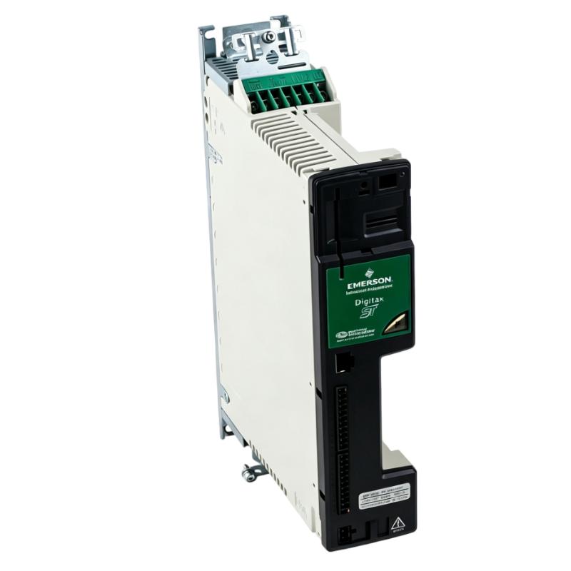
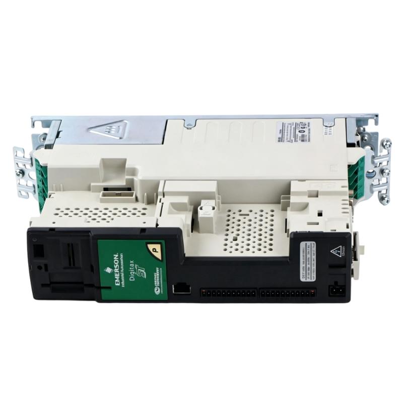
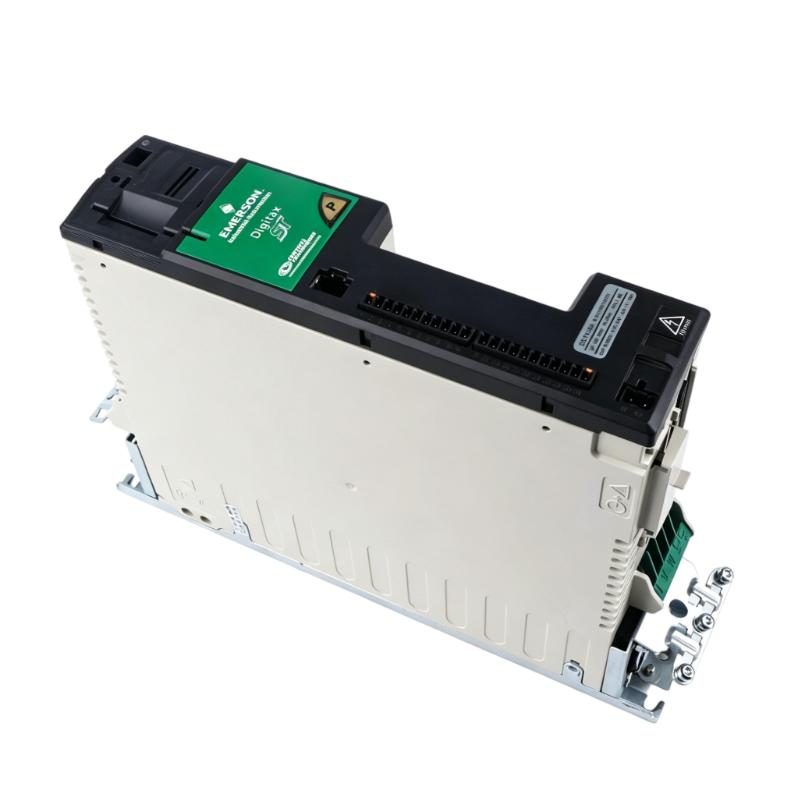
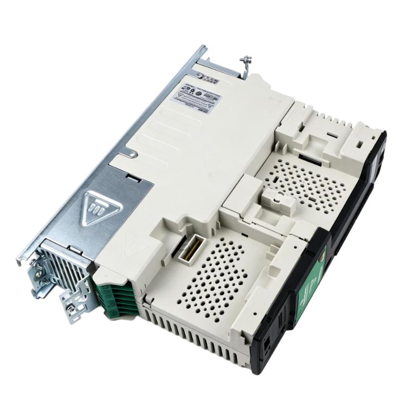
- Emerson
- DST1404
- Servo Drive
- USA
- 322 × 62 × 226 mm
- 2.1 kg
- Xiamen, China
- New & In Stock
- T/T, PayPal, Western Union
- 1 Year
- 1-3 Working Days
- DHL, UPS, TNT, FedEx and EMS.
- 24-Hour Service
- COO
- 6
Our advantage

Global Logistics
We have a 10-year logistics and express cooperation agreement, so our products can be shipped to any place in the world.

Brand new and original
Our products are imported in bulk from the place of origin. Because of the cooperative relationship, our products are all original and 100% new.

24-hour service
We provide 7*24 hours service to our customers. We will be there whenever you need us.

Price advantage
All our products are priced very favorably because we have our own warehouse and supply.
| Company Information | |||
| [email protected] | |||
| Mobile | +8615980777398 | ||
| +8615980777398 | |||
| 15980777398 |
Product Overview
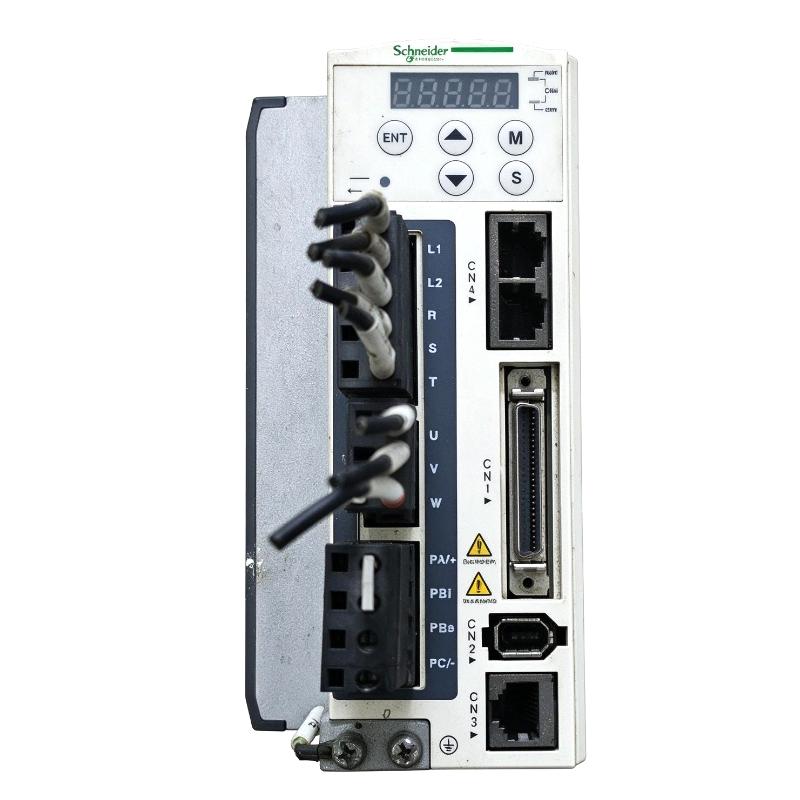
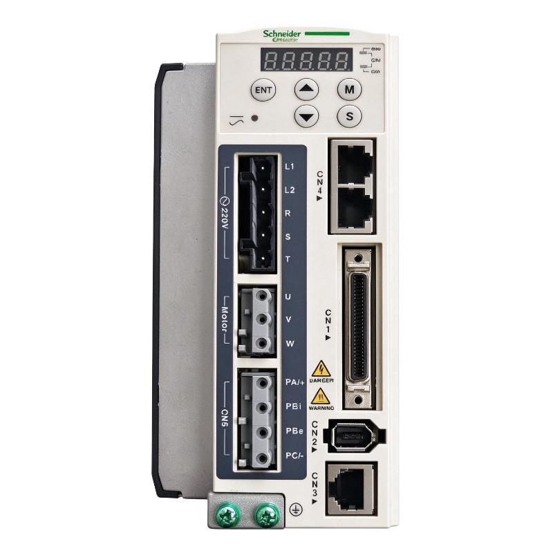
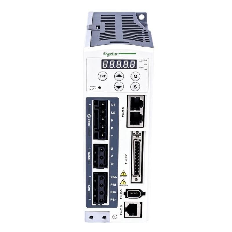
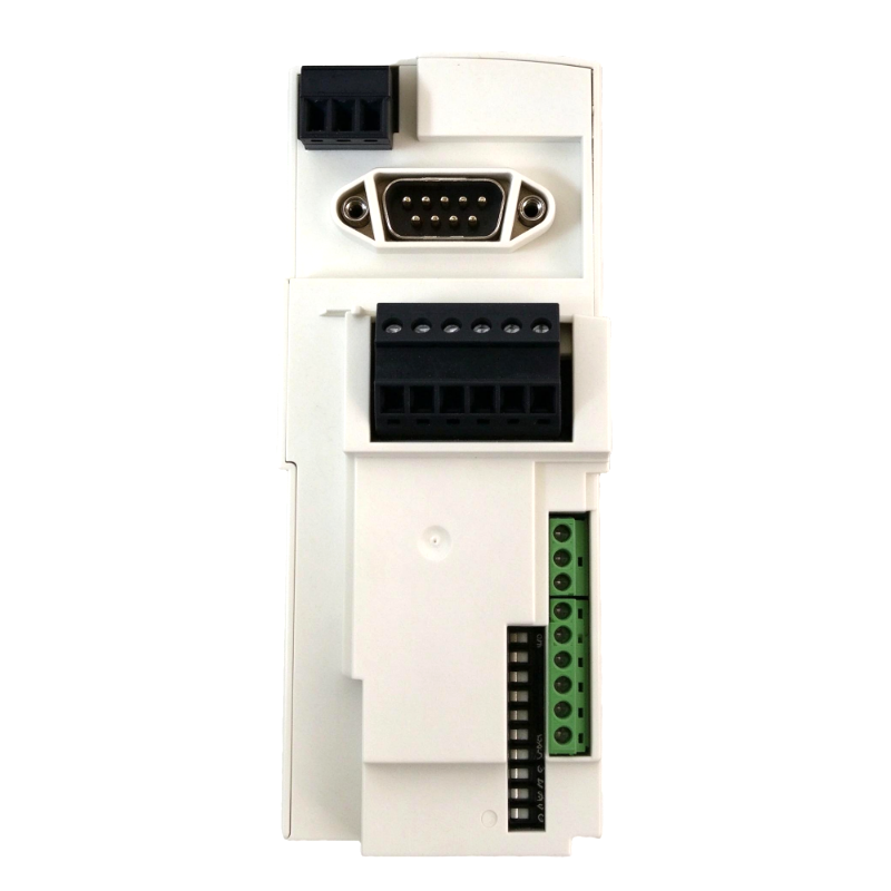
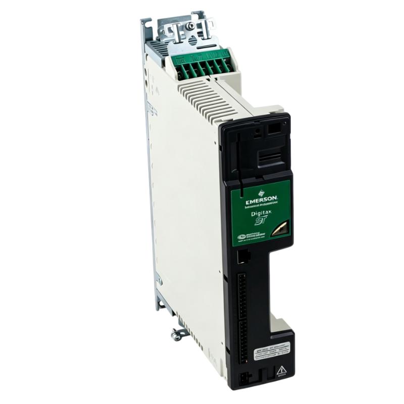
The Emerson DST1404 Digitax ST Servo Drive is an AC servo drive in the Digitax ST family, intended for controlling servo motors in industrial motion applications. Its 5.9 A rated output current and 17.7 A peak output current place it above the DST1401, DST1402 and DST1403 in the same 380–480 V drive range.
The DST1404 is suitable for servo axes that require higher current capacity during acceleration, rapid repositioning or changes in mechanical load. Typical applications include automated assembly machinery, packaging lines, indexing systems and material-handling equipment, where the motor must follow a programmed motion profile while remaining coordinated with other machine operations.
In an indexing machine, for example, a motor may need to accelerate a loaded turntable, bring it to a precise stopping position and hold the required operating state while another process takes place. The drive regulates the motor’s electrical output, while the motion controller determines the movement sequence. Selecting the correct current rating requires consideration of the motor specifications, load inertia, acceleration time and operating cycle.
The DST1404 uses a three-phase 380–480 V AC supply and an internal fan cooling arrangement. When installing it in an existing Digitax ST system, engineers should verify the complete drive variant, motor feedback compatibility, control interface and braking requirements. Sharing the same product family does not guarantee that two drive models can be exchanged without checking their electrical ratings and configuration.
Technical Specifications
| Parameter | Specification |
|---|---|
| Manufacturer | Emerson / Control Techniques |
| Model / Part Number | DST1404 |
| Product Family | Digitax ST |
| Product Type | AC Servo Drive |
| Frame Size | Frame Size 1 |
| Rated Supply Voltage | 380–480 V AC |
| Number of Input Phases | 3 |
| Rated Output Current | 5.9 A |
| Peak Output Current | 17.7 A |
| Peak Input Current | 8.0 A |
| Cooling Method | Internal fan |
| Drive Function | Servo motor control |
| Control Functions | Speed, torque and position control, according to the installed configuration |
| Application | Industrial servo motion control |
| Dimensions | 322 × 62 × 226 mm |
| Weight | 2.1 kg |
Product Features
- Three-phase AC input: Operates from the specified 380–480 V AC supply class.
- 5.9 A rated output current: Supports compatible servo motors with continuous current requirements within the drive’s rating.
- 17.7 A peak output current: Accommodates short-duration current demand within the permitted operating limits.
- Digitax ST platform: Integrates into compatible servo motion-control systems using the same drive family.
- Motor feedback control: Supports closed-loop operation when paired with a compatible feedback device and correctly configured control system.
- Internal fan cooling: Removes heat generated during drive operation.
- Configurable motor parameters: Allows motor data, current limits and control settings to be matched to the application.
- Optional interface capability: The Digitax ST range supports additional interface modules and control functions, depending on the installed drive variant.
Working Principle
The DST1404 converts incoming three-phase AC power into controlled electrical output for a compatible servo motor. It regulates motor current according to the selected operating mode and commands received from the machine’s motion-control system.
During acceleration, the drive supplies the current needed to generate motor torque against the combined inertia and resistance of the mechanical load. As the axis approaches its target speed or position, the control loop adjusts the output to follow the commanded motion profile. During deceleration, the drive manages the motor response and regenerative energy according to the configured braking arrangement.
Consider a packaging line where a loaded transfer mechanism must move rapidly between two stations. The motor may require substantial current during acceleration, followed by controlled deceleration to prevent excessive mechanical impact. The DST1404’s current ratings help determine whether it can meet the required motion profile, but actual performance also depends on the motor, feedback configuration and mechanical system.
The 17.7 A peak rating is intended for permitted short-duration demands, not continuous operation. Drive selection must account for overload duration, operating frequency, thermal conditions and the motor’s current requirements. The drive executes the configured motor-control function; the controller remains responsible for coordinating the axis with the wider machine sequence.
Role in a Digitax ST Servo Motion Control System
The DST1404 acts as the power-control stage between the electrical supply and the servo motor. It receives motion commands, regulates motor output and uses compatible feedback signals to control the motor’s response.
Three-Phase AC Supply → DST1404 Servo Drive → Servo Motor → Mechanical Axis
Motion Controller → Command Interface → DST1404 → Motor Feedback and Control Loop
| System Component | Function | Relationship to the DST1404 |
|---|---|---|
| Three-Phase AC Supply | Provides incoming electrical power | Supplies the drive’s input power |
| Input Circuit Protection | Protects the incoming electrical circuit | Must match the installation and drive requirements |
| DST1404 Servo Drive | Regulates motor current and executes configured control functions | Controls the connected servo motor |
| Compatible Servo Motor | Converts electrical energy into mechanical motion | Executes the commanded movement |
| Motor Feedback Device | Reports motor movement and position information | Supplies feedback to the supported drive interface |
| Motor Power Cable | Carries electrical output to the motor | Connects the drive to the motor |
| Feedback Cable | Transfers encoder or other supported feedback signals | Supports the motor feedback loop |
| Motion Controller or PLC | Generates motion commands and coordinates machine sequences | Determines the required axis movement |
| Braking Resistor, Where Required | Dissipates regenerative energy | Must be selected for the drive and braking duty |
| Mechanical Transmission | Transfers motor torque to the driven mechanism | Determines the mechanical load and inertia seen by the motor |
Industrial Applications
| Application | Typical Equipment | Role of the DST1404 |
|---|---|---|
| Packaging Machinery | Indexing tables, feed mechanisms and sealing stations | Controls repeated servo movements during production cycles |
| Automated Assembly | Positioning stations and transfer mechanisms | Executes programmed movements between assembly steps |
| Material Handling | Transfer tables and servo-driven conveyors | Regulates acceleration and positioning under changing loads |
| Printing and Converting | Web-feed and registration mechanisms | Controls material movement according to the production sequence |
| Labeling Equipment | Product indexing and feed axes | Supports controlled movement during label application |
| Machine Tools | Auxiliary positioning mechanisms | Controls compatible servo motors within the required current rating |
| Special-Purpose Machinery | Custom servo-driven mechanisms | Executes application-specific motion profiles |
| Industrial Retrofit Projects | Existing Digitax ST installations | Replaces a matching drive after electrical and control compatibility checks |
Installation and Maintenance
- Verify the drive reference: Confirm that DST1404 matches the required voltage class, current rating and control configuration.
- Check the incoming supply: Verify that the available three-phase AC supply falls within the specified 380–480 V range.
- Match the motor rating: Compare the motor’s continuous and peak current requirements with the drive’s ratings and permitted overload characteristics.
- Isolate the equipment: Follow the approved electrical isolation procedure and allow the specified DC-bus discharge time before handling the drive.
- Inspect cabinet ventilation: Ensure that the internal fan has adequate airflow and that the mounting arrangement meets the installation requirements.
- Examine the power terminals: Check the incoming supply, motor output and protective earth connections for damage or loose terminations.
- Verify feedback wiring: Confirm that the motor feedback device, cable and drive interface are compatible.
- Check motor parameters: Verify the motor data, control mode, current limits and feedback settings before enabling the drive.
- Review braking requirements: Determine whether the application’s inertia and stopping cycle require a braking resistor or another approved energy-management arrangement.
- Inspect control wiring: Check command signals, enable circuits, interlocks and any installed option modules.
- Commission the axis: Test motor direction, feedback response, acceleration, deceleration and positioning under controlled conditions.
- Record service information: Document the drive reference, motor configuration, parameter settings, fault history and commissioning results.
Compatible System Components
| Component | Function | Compatibility Consideration |
|---|---|---|
| Digitax ST Servo Motor | Converts drive output into mechanical motion | Match motor voltage, continuous current, peak current and feedback requirements |
| Motor Power Cable | Connects the drive output to the motor | Verify cable rating, connector arrangement and installation requirements |
| Encoder Feedback Cable | Transfers motor feedback signals | Confirm compatibility with the installed feedback device |
| Motion Controller | Generates axis commands and machine sequences | Verify the command interface and control architecture |
| Braking Resistor | Dissipates regenerative energy where required | Select according to drive compatibility and braking duty |
| Input Circuit Protection | Protects the incoming power circuit | Size according to the drive and installation requirements |
| Line Reactor, Where Required | Addresses supply-side electrical conditions | Determine the need from the supply characteristics and installation guidance |
| Digitax ST Keypad | Provides local access to drive parameters | Verify the supported keypad interface |
| Digitax ST Option Module | Adds supported communication or control functions | Check the specific drive variant and module requirements |
Recommended Related Models
| Model / Product | Product Type | Relationship | Selection Consideration |
|---|---|---|---|
| Emerson DST1401 | Digitax ST AC Servo Drive | Lower-current model in the same voltage class | Rated at 1.5 A continuous and 4.5 A peak output current |
| Emerson DST1402 | Digitax ST AC Servo Drive | Lower-current model in the same voltage class | Rated at 2.7 A continuous and 8.1 A peak output current |
| Emerson DST1403 | Digitax ST AC Servo Drive | Lower-current model in the same voltage class | Rated at 4.0 A continuous and 12.0 A peak output current |
| Emerson DST1405 | Digitax ST AC Servo Drive | Higher-current model in the same voltage class | Rated at 8.0 A continuous and 24.0 A peak output current |
| Emerson DST1204 | Digitax ST AC Servo Drive | Related drive in the 200–240 V AC family | Has a different supply-voltage class; verify the complete electrical requirements |
| Emerson Digitax ST Keypad | Drive Keypad | Accessory for supported local drive operation | Confirm the keypad interface and installed drive configuration |
| Emerson Digitax ST Braking Resistor | Braking Accessory | Used where regenerative energy must be dissipated | Check the required resistance, power rating and drive compatibility |
Key Advantages
- Operates from a three-phase 380–480 V AC supply.
- Provides 5.9 A rated output current and 17.7 A peak output current.
- Supports servo motor control with compatible feedback equipment.
- Uses internal fan cooling.
- Fits suitable installations using the Digitax ST Frame Size 1 configuration.
Technical FAQs
How does the DST1404 differ from the DST1403?
The DST1404 has a rated output current of 5.9 A and a peak output current of 17.7 A, compared with 4.0 A and 12.0 A for the DST1403. The appropriate model depends on the motor’s current demand, required acceleration and operating duty.
What should be considered when using the DST1404 for a high-inertia load?
Evaluate the load inertia, acceleration and deceleration times, stopping frequency and motor current requirements. The drive must remain within its continuous and permitted peak operating limits, and the braking arrangement must be suitable for the regenerative energy generated during deceleration.
Can the DST1404 replace a lower-current Digitax ST drive without changing the motor?
Not automatically. The supply voltage, motor ratings, feedback interface, control variant, wiring and parameter configuration must all be checked. A higher drive current rating alone does not establish full system compatibility.
What could cause the DST1404 to overheat during normal operation?
Possible causes include inadequate cabinet airflow, an obstructed cooling fan, high ambient temperature, excessive motor current or a duty cycle beyond the intended operating limits. Review the installation conditions and recorded operating data before replacing the drive.