

ProductPRODUCT
Featured products
Contact Us
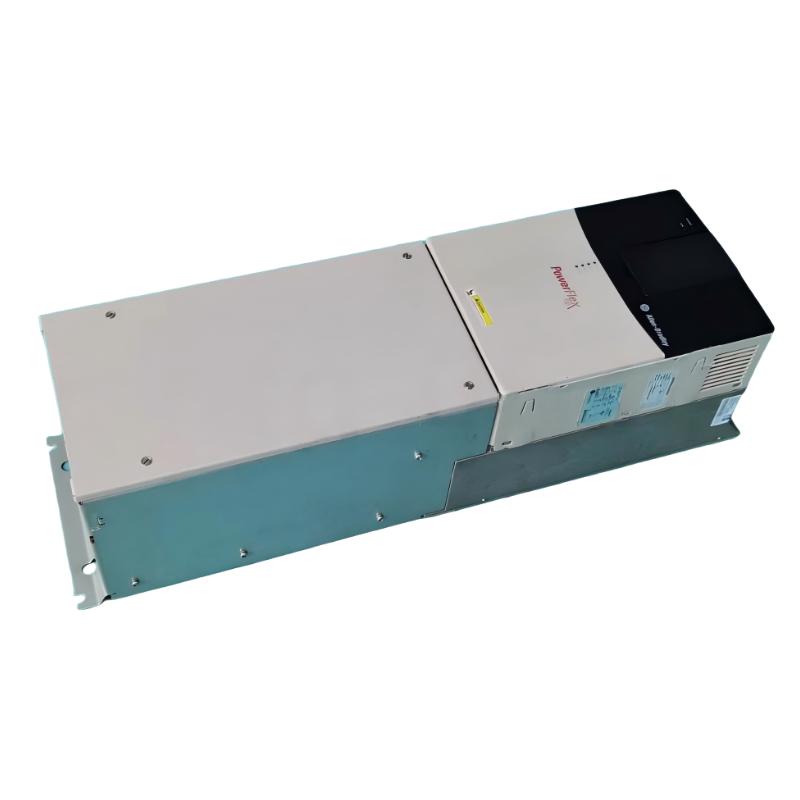
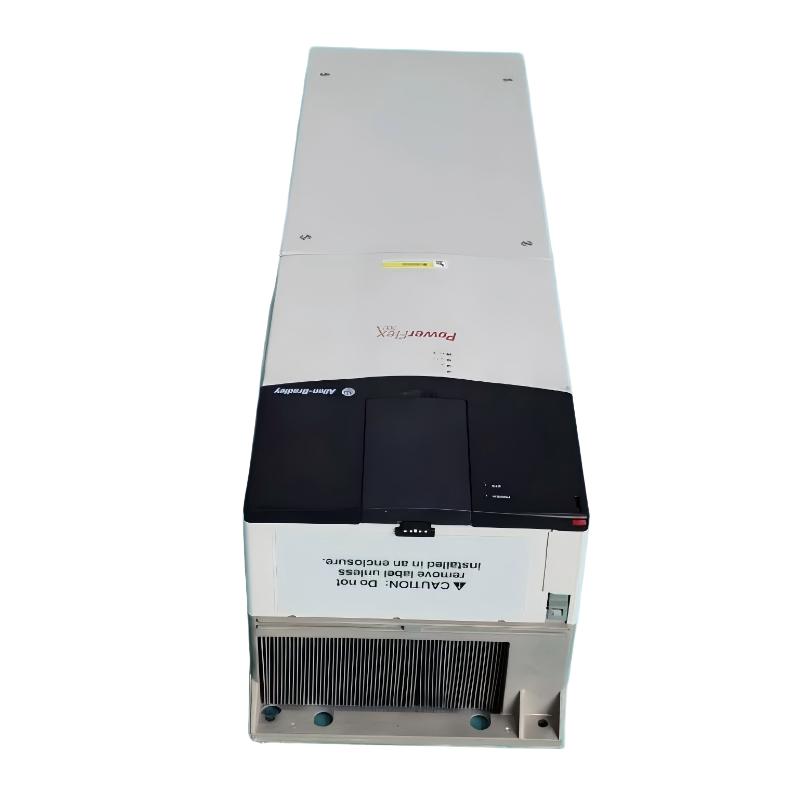
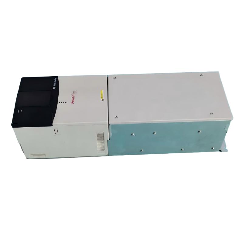
- Allen Bradley
- 20BH260A0ANNANC0
- PowerFlex AC Drive
- USA
- 689.6 × 308.9 × 275.4 mm
- 14.51kg
- Xiamen, China
- New & In Stock
- T/T, PayPal, Western Union
- 1 Year
- 1-3 Working Days
- DHL, UPS, TNT, FedEx and EMS.
- 24-Hour Service
- COO
- 19
Our advantage

Global Logistics
We have a 10-year logistics and express cooperation agreement, so our products can be shipped to any place in the world.

Brand new and original
Our products are imported in bulk from the place of origin. Because of the cooperative relationship, our products are all original and 100% new.

24-hour service
We provide 7*24 hours service to our customers. We will be there whenever you need us.

Price advantage
All our products are priced very favorably because we have our own warehouse and supply.
| Company Information | |||
| [email protected] | |||
| Mobile | +8615980777398 | ||
| +8615980777398 | |||
| 15980777398 |
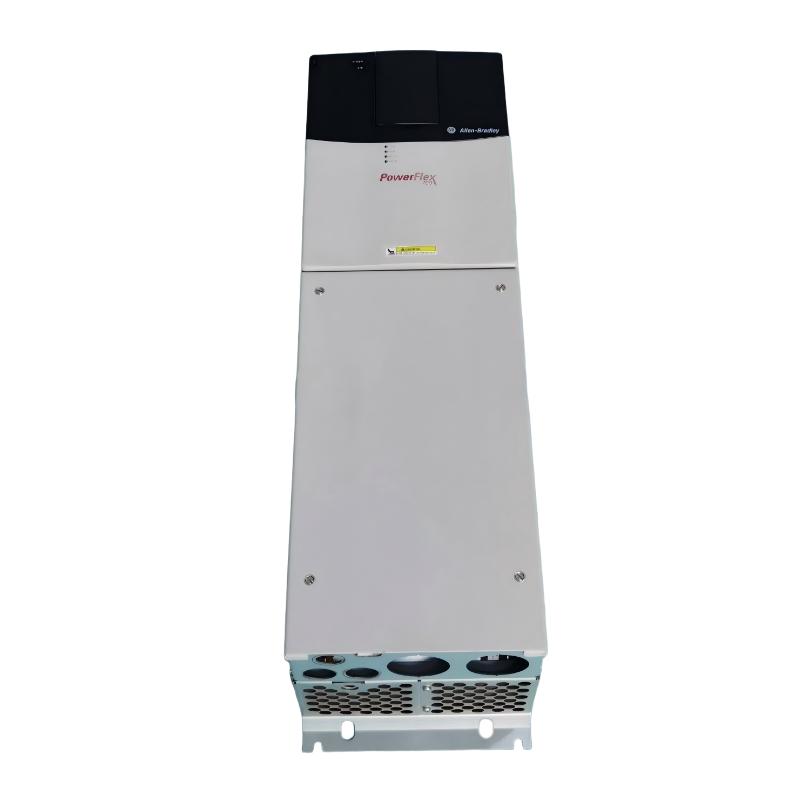
Allen-Bradley 20BH260A0ANNANC0 — Product Specifications, Technical Overview, Applications, Advantages, and Related Models
1. Product Overview
The Allen-Bradley 20BH260A0ANNANC0 is a catalog number associated with the PowerFlex 700 family of industrial adjustable-frequency AC drives. This type of equipment is used to regulate the speed and torque of compatible electric motors in manufacturing plants, process facilities, material-handling systems, and other industrial environments.
An adjustable-frequency drive controls motor operation by changing the frequency and voltage supplied to the motor. This makes it possible to adapt machine speed to changing production requirements, control acceleration and deceleration, and coordinate motor operation with other automation equipment.
The PowerFlex 700 family is designed for industrial applications that require configurable motor control and integration into automated operating systems. Typical uses include pumps, fans, conveyors, compressors, mixers, and other machinery that benefits from variable-speed operation.
Catalog identification note: The exact electrical ratings, enclosure, dimensions, weight, and installed options of the complete 20BH260A0ANNANC0 configuration must be confirmed against the unit’s nameplate and mechanical documentation. The model number alone is not sufficient to establish every specification with confidence.
2. Detailed Product Parameters
The following table summarizes the product’s identification and functional characteristics. Values that depend on the complete catalog configuration are marked for verification rather than estimated.
| Parameter | Specification |
|---|---|
| Brand | Allen-Bradley |
| Model number | 20BH260A0ANNANC0 |
| Product series | PowerFlex 700 |
| Product category | Industrial adjustable-frequency AC drive |
| Product function | Variable-speed motor control |
| Catalog family | 20B |
| Current rating | The model designation indicates a 260 A configuration; confirm the rated output current on the nameplate |
| Rated power | Depends on supply voltage, duty rating, and motor application |
| Input voltage | Confirm from the complete catalog specification and nameplate |
| Input phase | Verify the specific configuration |
| Output frequency | Depends on the drive configuration and parameter settings |
| Motor compatibility | Compatible three-phase AC motors, subject to voltage, current, and control requirements |
| Control methods | V/Hz and vector-control capabilities, depending on the installed configuration |
| Speed regulation | Adjustable through configured references and control parameters |
| Acceleration and deceleration | Programmable, within the drive’s operating limits |
| Protection functions | Available functions depend on the drive hardware and configuration |
| Communication | Depends on installed communication hardware |
| Operator interface | Confirm the installed interface and control options |
| Enclosure protection | Verify the exact enclosure and protection classification |
| Cooling | Depends on the drive frame and installation configuration |
| Dimensions (H × W × D) | Exact dimensions require the matching mechanical drawing |
| Weight (kg) | Exact equipment weight requires confirmation for the complete configuration |
| Installation type | Industrial mounting arrangement appropriate to the drive frame and enclosure |
| Product lifecycle | The PowerFlex 700 20B family is discontinued; assess serviceability and replacement options |
Electrical Rating Considerations
The 260 A designation is a useful starting point when identifying the drive, but it should not be used as the only basis for selection.
Drive current capacity can vary according to operating voltage, normal-duty or heavy-duty rating, ambient temperature, switching frequency, and other derating requirements. The motor’s rated current and overload demands must be checked before selecting a replacement.
Dimensions and Weight
The exact physical dimensions and weight of the 20BH260A0ANNANC0 are not confirmed here. These values should be obtained from the matching mechanical drawing or equipment documentation.
For installation and transport planning, distinguish between the weight of the drive assembly and the total weight of an enclosed or packaged system. Cabinet dimensions, ventilation clearance, cable access, and lifting requirements must also be considered.
3. Product Introduction
3.1 Purpose and Operating Principle
The PowerFlex 700 is designed to regulate the operation of industrial AC motors. In a conventional fixed-speed installation, the motor operates at approximately its normal operating speed whenever it is energized. Process output may then be controlled using mechanical devices, such as valves, dampers, or other regulating equipment.
An adjustable-frequency drive provides another approach. It regulates the electrical supply delivered to the motor, allowing the motor to operate at different speeds according to the process requirements.
For example, a pump may need to deliver different flow rates during different production stages. A fan may need to adjust airflow according to cooling demand. A conveyor may need to run slowly during loading and faster during normal production.
By controlling motor speed directly, a drive can help match mechanical output to the actual operating requirement.
3.2 Industrial Motor Control
The PowerFlex 700 family is intended for industrial environments where motors must operate reliably under changing loads and operating conditions.
Depending on the configuration, the drive can support adjustable speed references, programmed acceleration and deceleration, current limiting, and application-specific motor-control settings.
These functions are particularly useful when equipment must start smoothly, respond to process commands, or operate at several different speeds during a production cycle.
Correct commissioning remains essential. The drive must be configured using the appropriate motor nameplate data, control parameters, protective settings, and application requirements.
3.3 Configurable Control Functions
Different applications place different demands on an AC drive. A pump may prioritize stable flow regulation, while a conveyor may require controlled starting and adequate torque during acceleration.
The PowerFlex 700 family provides configurable motor-control functions that can be adapted to different applications, subject to the installed hardware and supported firmware.
Available functions and accessories must be confirmed for the exact catalog number. Features found on one configuration should not automatically be assumed to be present on another.
3.4 Integration with Industrial Automation
In an automated production environment, a drive is often connected to a programmable controller, operator interface, sensors, and protective devices.
Depending on its installed options, the drive may receive run commands and speed references while reporting operating status, faults, and other control information.
This arrangement allows the motor to operate as part of a coordinated process instead of being controlled independently.
Before connecting the 20BH260A0ANNANC0 to an existing system, verify the communication interface, control wiring, available inputs and outputs, firmware compatibility, and the behavior required during faults or communication loss.
4. Product Applications
4.1 Industrial Pumping Systems

Pumping systems are among the common applications for adjustable-frequency drives. Motor speed can be adapted to changing flow demand when the pump and hydraulic system are suitable for variable-speed operation.
Typical applications include:
-
Industrial water circulation.
-
Process-fluid transfer.
-
Water treatment equipment.
-
Cooling-water systems.
-
Industrial supply and distribution pumps.
A properly selected drive can improve flow regulation and reduce unnecessary energy consumption in suitable applications.
However, pump performance depends on the pump curve, system resistance, static head, fluid characteristics, and required minimum flow. These factors should be evaluated before setting the operating speed range.
4.2 Industrial Fans and Ventilation Systems

Fans and ventilation equipment often operate under varying airflow requirements. A variable-speed drive allows the motor to adjust fan speed rather than depending entirely on mechanical dampers.
Applications include:
-
Factory ventilation.
-
Industrial exhaust systems.
-
Cooling towers.
-
Air-handling equipment.
-
Process cooling and circulation.
Speed control can help regulate airflow and may reduce energy consumption when the fan operates below its full-speed condition for substantial periods.
Engineers must still verify fan speed limits, motor cooling, mechanical balance, and possible resonance within the operating range.
4.3 Conveyor and Material-Handling Systems

Conveyors transport products, components, raw materials, and finished goods throughout industrial facilities. Adjustable-speed control allows conveyor operation to match production requirements.
Typical uses include packaging lines, assembly systems, sorting equipment, material-transfer systems, and manufacturing conveyors.
The drive can provide controlled acceleration and deceleration, helping limit abrupt mechanical loading and reducing sudden movement of transported materials.
For systems with several motors, engineers should evaluate synchronization, load distribution, stopping behavior, and braking requirements.
4.4 Compressors and Process Equipment

Certain compressors and process machines can benefit from variable-speed operation when their mechanical design supports it.
The drive can adjust motor speed to changing process demand, potentially improving operating flexibility. However, compressor type, lubrication, cooling, pressure requirements, minimum speed, and mechanical limitations must be considered.
A variable-frequency drive should not be assumed suitable for every compressor merely because the motor’s voltage and current appear compatible.
4.5 Mixers, Agitators, and General Industrial Machinery

Mixers, agitators, and similar machinery may require different speeds during startup, processing, and discharge.
An adjustable-frequency drive can support these operating stages by providing controlled speed references and acceleration profiles.
For high-inertia loads or machinery requiring substantial starting torque, engineers should check the load torque curve, acceleration time, motor thermal capacity, and drive overload rating.
4.6 Manufacturing and Production Lines
In manufacturing facilities, adjustable-speed drives can help coordinate machinery that must operate at different rates during production.
Typical applications include assembly equipment, packaging machinery, material feeders, production auxiliaries, and process transport systems.
The primary benefit is the ability to adapt motor operation to the production process. The drive’s suitability depends on its current rating, control features, communication requirements, and compatibility with the machine’s electrical design.
5. Main Product Advantages
5.1 Flexible Motor-Speed Adjustment
The drive allows compatible motors to operate at different speeds according to process requirements.
This can be useful when production demand changes during a shift or when a machine must operate at different speeds for loading, processing, and unloading.
5.2 Controlled Acceleration and Deceleration
Programmable acceleration and deceleration can help reduce abrupt changes in mechanical loading.
Depending on the application, controlled ramps may reduce stress on couplings, belts, gearboxes, and driven equipment. The actual effect depends on machine design and the selected operating parameters.
5.3 Potential Energy Savings
In suitable pump and fan applications, reducing motor speed can lower energy consumption compared with operating continuously at full speed and restricting output mechanically.
The amount of energy saved depends on the load characteristics, operating schedule, system design, and required process output.
Energy savings should be evaluated using actual operating data rather than assumed from the presence of a drive alone.
5.4 Adaptability to Different Applications
Configurable motor-control settings allow engineers to adjust drive behavior for different loads and operating conditions.
Parameters such as acceleration time, deceleration time, speed reference, current limits, and stopping method can be selected according to the machine’s needs.
The available options must be verified for the particular drive configuration.
5.5 Support for Automated Control
When the appropriate communication and control options are installed, the drive can work with compatible automation equipment.
This supports coordinated machine operation, centralized monitoring, fault handling, and process sequencing.
5.6 Improved Operating Flexibility
A single motor-driven machine may need to perform several tasks at different speeds. Adjustable-speed control can accommodate these operating stages without relying exclusively on mechanical speed-changing devices.
This is useful in production systems where operating requirements vary during the day.
5.7 Familiarity in Existing Industrial Installations
Facilities that already use the PowerFlex 700 family may have existing engineering documentation, parameter records, maintenance procedures, or personnel familiar with the equipment.
Maintaining a compatible drive may reduce the immediate need for extensive control-system changes. However, lifecycle planning is especially important because the 20B family has been discontinued.
6. Brand and Series Information
| Item | Description |
|---|---|
| Brand | Allen-Bradley |
| Product family | PowerFlex |
| Product series | PowerFlex 700 |
| Catalog family | 20B |
| Product type | Industrial adjustable-frequency AC drive |
| Main function | Motor speed and torque regulation |
| Intended environment | Industrial motor-control installations |
| Typical applications | Pumps, fans, conveyors, compressors, mixers, and process machinery |
| Integration | Depends on installed communication and control options |
| Lifecycle consideration | Discontinued product family; confirm parts availability and replacement strategy |
The complete catalog number is important because closely related drives may have different electrical ratings, enclosure types, control interfaces, and installed accessories.
For replacement purposes, the catalog number and nameplate should be checked alongside the physical configuration. A similar-looking unit is not necessarily electrically or mechanically interchangeable.
7. Five Related Models for Comparison
The following table provides related model candidates for technical evaluation. Some entries are representative comparison targets rather than fully verified ordering codes. Their complete specifications must be established before purchase.
| Model | Series | Key parameters | Dimensions (H × W × D) | Weight (kg) |
|---|---|---|---|---|
| 20BH205A0ANNANC0 | PowerFlex 700 | Related 205 A configuration; confirm voltage, duty rating, and enclosure | Verify exact drawing | Verify |
| 20BH260A0ANNANA0 | PowerFlex 700 | Closely related catalog configuration; verify the suffix and installed options | Verify exact drawing | Verify |
| 20BH105A0ANNANC0 | PowerFlex 700 | Related 105 A model designation; verify supply voltage and duty rating | Verify exact drawing | Verify |
| 20B-series 260 A variant | PowerFlex 700 | Compare current capacity, enclosure, braking, and communication options | Depends on configuration | Verify |
| 20B-series higher-current variant | PowerFlex 700 | Consider only when motor-current and overload calculations justify the rating | Depends on configuration | Verify |
Model Comparison Notes
20BH205A0ANNANC0: This related model has a different current designation from the requested 260 A model. It may be relevant where the motor and load require a lower drive rating, but a lower-rated drive must not be substituted without checking the motor’s actual current and overload demand.
20BH260A0ANNANA0: This is presented as a suffix-comparison candidate, not a confirmed interchangeable replacement. Differences in the final catalog characters may indicate configuration changes, so the complete ordering information must be checked.
20BH105A0ANNANC0: This is a lower-current comparison candidate. It should only be considered for applications where its confirmed rating is adequate.
The remaining entries describe categories of related configurations rather than exact catalog numbers. They are included to show which characteristics should be compared when searching for a compatible drive.
8. Five Additional Models from Related Allen-Bradley PowerFlex Families
The following models represent alternative drive families for different motor sizes and application requirements. They are comparison candidates rather than direct replacements for the 20BH260A0ANNANC0.
| Model | Product series | Main parameters | Typical applications | Dimensions (H × W × D) | Weight (kg) |
|---|---|---|---|---|---|
| 20G11ND077AA0NNNNN | PowerFlex 755 | 77 A model designation; verify voltage class, duty rating, and options | Industrial motor control and automation | Verify exact drawing | Verify |
| 20F11NC060JA0NNNNN | PowerFlex 753 | 60 A model designation; confirm electrical rating and installed options | Pumps, fans, and general industrial machinery | Verify exact drawing | Verify |
| 25B-D017N104 | PowerFlex 525 | 17 A model designation; confirm supply voltage and power rating | Compact machinery, conveyors, and packaging equipment | Verify exact drawing | Verify |
| 22B-D012N104 | PowerFlex 40 | 12 A model designation; confirm voltage and motor rating | General-purpose compact drive applications | Verify exact drawing | Verify |
| 22F-D013N104 | PowerFlex 4M | Compact drive configuration; confirm current, voltage, and power rating | Small machinery and auxiliary equipment | Verify exact drawing | Verify |
How to Interpret the Alternatives
The PowerFlex 753 and 755 families are relevant when evaluating industrial drive architectures with different control and integration requirements.
The PowerFlex 525, PowerFlex 40, and PowerFlex 4M families are compact-drive alternatives intended for different motor-power ranges and applications. Their smaller size does not make them suitable replacements for a higher-current drive without a full electrical and mechanical assessment.
Before selecting any model, confirm its complete catalog number, rated output current, input voltage, overload capability, control functions, enclosure, and installation requirements.
9. Technical Selection Checklist
| Selection item | Required verification | Reason |
|---|---|---|
| Supply voltage | Confirm actual supply voltage and drive voltage class | Prevents electrical mismatch |
| Output current | Check the motor’s full-load current and the drive’s rated current | Establishes current compatibility |
| Motor power | Confirm motor kW or HP at the applicable voltage | Helps identify a suitable drive size |
| Duty rating | Establish normal-duty or heavy-duty requirements | Determines allowable overload performance |
| Starting torque | Assess breakaway torque and acceleration demand | Prevents inadequate starting performance |
| Load inertia | Calculate acceleration and deceleration requirements | Helps determine drive and braking needs |
| Control method | Confirm V/Hz or vector-control requirements | Supports the required motor behavior |
| Feedback | Establish whether encoder or other feedback is necessary | Important for precise speed regulation |
| Braking | Confirm stopping method and dynamic braking requirements | Affects hardware selection and stopping performance |
| Communication | Identify the required network and control interface | Ensures automation compatibility |
| Enclosure | Check protection, ambient conditions, and contamination | Supports reliable installation |
| Dimensions | Obtain exact height, width, depth, and clearances | Ensures the unit fits the installation |
| Weight | Confirm net equipment and shipping weights | Supports handling and mounting |
| Lifecycle | Assess repair options and spare-parts availability | Reduces maintenance and downtime risk |
10. Installation and Maintenance
10.1 Installation Requirements
The drive should be installed by qualified personnel in accordance with the applicable electrical and machinery requirements.
Before installation, verify the supply voltage, grounding, short-circuit protection, cable sizing, motor compatibility, enclosure protection, and environmental conditions.
The mounting location must provide sufficient cooling airflow and the clearances specified for the particular frame and enclosure. Excessive heat, conductive dust, moisture, or corrosive contamination can affect reliability.
10.2 Commissioning Requirements
Commissioning should begin with verification of the motor nameplate data, control wiring, protective settings, and communication interfaces.
The acceleration and deceleration parameters, speed references, motor-control method, and stopping behavior should be configured for the application.
Initial tests should confirm correct motor rotation, stable operation, expected current draw, and appropriate responses to stop commands and faults.
10.3 Preventive Maintenance
A preventive maintenance program should include visual inspection, cooling-path inspection, cleaning according to the applicable instructions, and checking for abnormal temperature, noise, or fault behavior.
Electrical connections and power components should be assessed according to the relevant maintenance procedures.
Before maintenance, isolate the supply and follow the specified DC-bus discharge and voltage-verification procedures. Hazardous voltage can remain present after power has been removed.
10.4 Lifecycle Planning
Because the PowerFlex 700 20B family is discontinued, the long-term availability of replacement units, repair services, and spare parts should be evaluated.
If the existing drive is critical to production, it is useful to document its complete catalog number, firmware, parameter settings, control interfaces, and mechanical dimensions.
A replacement plan should consider not only the drive itself but also changes that may be needed in the cabinet, wiring, control system, and commissioning process.
11. Frequently Asked Questions
What is the main function of the 20BH260A0ANNANC0?
It is associated with the PowerFlex 700 family of industrial adjustable-frequency drives. Its purpose is to regulate the speed and torque of compatible AC motors in industrial applications.
Does the model number confirm a 260 A output rating?
The model designation indicates a 260 A configuration, but the actual rated output current must be verified from the complete catalog documentation and nameplate.
Can the 20BH205A0ANNANC0 replace it?
Not automatically. The two models have different current designations. A replacement must satisfy the motor’s electrical requirements, overload demand, control needs, and installation constraints.
Can a compact PowerFlex drive replace this model?
A compact drive should not be treated as a direct replacement solely because it can control an AC motor. The current rating, voltage class, overload capability, braking requirements, and control interfaces must all be compatible.
What are the exact dimensions and weight?
The exact height, width, depth, and weight of the complete 20BH260A0ANNANC0 configuration are not established in this description. The matching mechanical drawing and equipment documentation should be used to obtain these values.
What is the principal advantage of the PowerFlex 700 family?
Its primary advantage is configurable industrial motor control, including variable-speed operation, controlled acceleration and deceleration, and integration options appropriate to the installed configuration.
12. Final Product Summary
The Allen-Bradley 20BH260A0ANNANC0 is associated with the PowerFlex 700 industrial AC drive family and is intended for applications requiring controlled motor operation.
Its potential applications include industrial pumping, ventilation, conveyors, compressors, mixers, and general manufacturing equipment. The main benefits of adjustable-frequency operation include flexible speed control, controlled starting and stopping, improved process adaptability, and potential energy savings in suitable applications.
For engineering and purchasing purposes, the most important considerations are:
1. Electrical compatibility: Confirm the rated voltage, output current, motor power, and duty rating.
2. Mechanical compatibility: Verify the exact dimensions, installation clearances, enclosure, and weight in kilograms.
3. Control compatibility: Check the required communication interfaces, feedback options, braking arrangements, and control functions.
4. Lifecycle planning: Evaluate repair support, spare parts, and replacement feasibility because the PowerFlex 700 20B family is discontinued.
5. Model verification: Treat related model numbers as comparison candidates until their complete catalog configurations have been checked.
The model tables above provide a structured starting point for technical comparison. Exact physical specifications should remain unconfirmed until the appropriate dimensional drawing and equipment documentation are available; assigning unsupported dimensions or weights could lead to incorrect procurement or installation decisions.