

ProductPRODUCT
Featured products
Contact Us
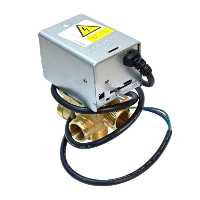
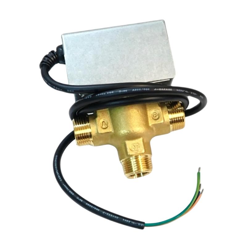
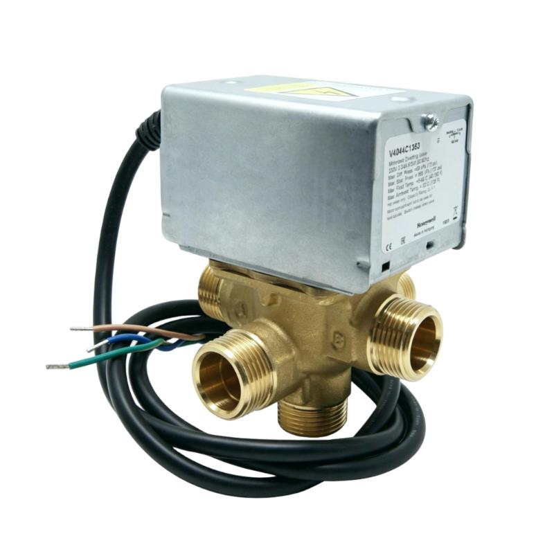
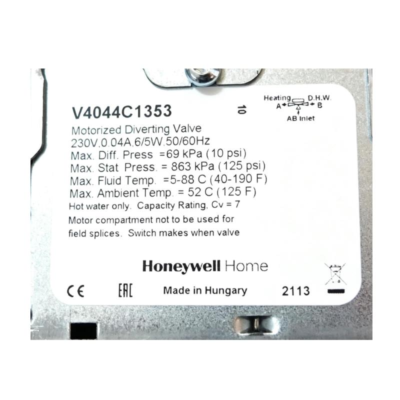
- Honeywell
- V4044C1353
- 3-Way Diverting Motorized Valve
- USA
- 19.05 mm
- 1.6 kg
- Xiamen, China
- New & In Stock
- T/T, PayPal, Western Union
- 1 Year
- 1-3 Working Days
- DHL, UPS, TNT, FedEx and EMS.
- 24-Hour Service
- COO
- 5
Our advantage

Global Logistics
We have a 10-year logistics and express cooperation agreement, so our products can be shipped to any place in the world.

Brand new and original
Our products are imported in bulk from the place of origin. Because of the cooperative relationship, our products are all original and 100% new.

24-hour service
We provide 7*24 hours service to our customers. We will be there whenever you need us.

Price advantage
All our products are priced very favorably because we have our own warehouse and supply.
| Company Information | |||
| [email protected] | |||
| Mobile | +8615980777398 | ||
| +8615980777398 | |||
| 15980777398 |
Product Overview
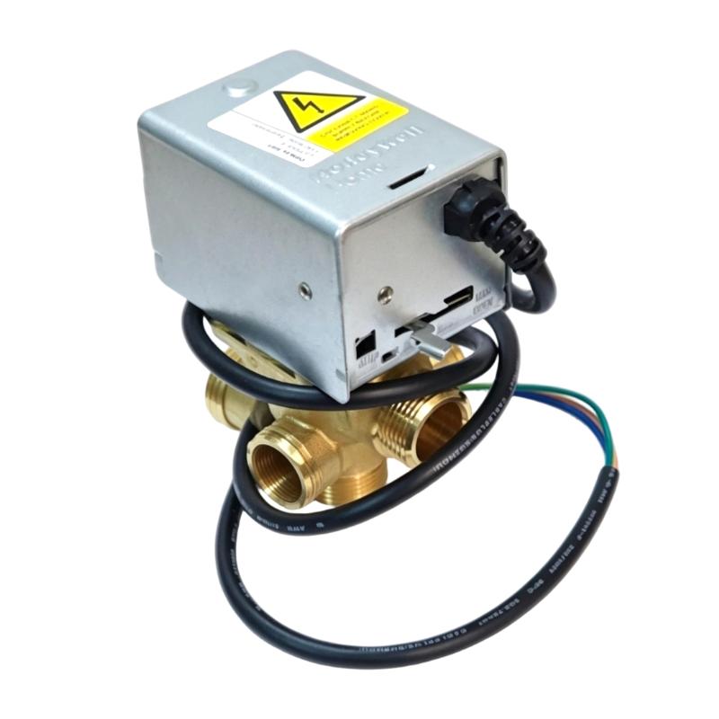
The Honeywell V4044C1353 is a 3-Way Diverting Motorized Valve used to direct fluid flow between connected piping paths in HVAC and hydronic control systems. Its motorized actuator allows the valve position to be controlled electrically, making it suitable for automatic flow-diverting applications.
A three-way diverting valve is commonly used where one supply flow must be directed toward different branches according to the operating condition. In a heating or cooling system, for example, the valve can change the flow path in response to a controller command, allowing the system to manage heat transfer, zone conditions, or equipment operating modes.
The V4044C1353 combines the valve body and motorized operating mechanism into a controlled flow device. The actuator moves the internal valve mechanism according to the control signal, while the valve body determines which connected flow path is open or restricted.
In practical installations, correct valve selection depends not only on the actuator and control arrangement but also on the fluid service, piping configuration, flow direction, and system control sequence. The valve should therefore be installed as part of the complete hydronic or fluid-control loop.
Technical Specifications
| Parameter | Specification |
|---|---|
| Manufacturer | Honeywell |
| Model | V4044C1353 |
| Product Type | 3-Way Diverting Motorized Valve |
| Valve Type | 3-Way Diverting Valve |
| Actuation | Motorized |
| Application | Automatic fluid-flow diversion |
| System Role | Flow-path control |
| Typical System | HVAC and hydronic control systems |
| Control Function | Directs flow between connected piping paths |
| Diameter | 19.05 mm |
| Weight | 1.6 kg |
Product Features
- Three-way valve arrangement for automatic flow diversion.
- Motorized actuation allows the valve position to be controlled electrically.
- Suitable for HVAC and hydronic system applications.
- Directs fluid between alternative piping paths according to the control sequence.
- Supports automatic temperature and flow-management strategies.
- Can be integrated with building automation and equipment control systems.
- Suitable for applications requiring repeatable electrically controlled flow-path changes.
Working Principle
The V4044C1353 uses an electric motorized actuator to move the internal valve mechanism between its available flow positions. The controller determines the required valve position based on the operating condition of the system.
When the actuator receives the appropriate command, it changes the internal flow path so that fluid is diverted through the selected branch. The controller can use this function to regulate the distribution of heating or cooling fluid within the connected system.
Controller Command → Motorized Actuator → Valve Position → Flow Diversion → HVAC / Hydronic Equipment
The valve itself performs the physical flow routing, while the building or equipment controller determines when the flow path needs to change. Proper piping orientation and control sequencing are therefore important during installation.
Role in an HVAC and Hydronic Control Architecture
The V4044C1353 operates at the final control element layer of an HVAC or hydronic control architecture. The controller issues the operating command, while the motorized valve converts that command into a physical change in fluid flow direction.
| System Element | Function |
|---|---|
| Temperature / System Controller | Determines the required flow-control state |
| V4044C1353 | Diverts fluid between connected piping paths |
| Motorized Actuator | Moves the valve according to the control command |
| Circulation Pump | Provides the fluid movement required by the system |
| Heating / Cooling Equipment | Provides or removes thermal energy |
| Sensors | Supply temperature or operating-condition feedback |
| Building Automation System | Coordinates system control and monitoring |
Industrial Applications
| Application | Typical Use |
|---|---|
| HVAC Systems | Diverting heating or cooling fluid between system branches |
| Hydronic Heating | Controlling the flow path of heating water |
| Cooling Systems | Directing cooling fluid according to operating conditions |
| Air Handling Systems | Supporting automatic hydronic flow control |
| Building Automation | Providing motorized valve control from a central controller |
| Equipment Changeover | Switching fluid flow between alternative equipment or circuits |
Installation and Maintenance
- Verify the V4044C1353 model against the intended piping and control application before installation.
- Confirm the valve’s required flow direction and piping arrangement before connecting the system.
- Isolate the fluid circuit and release applicable system pressure before removing or installing the valve.
- Install the valve in the correct orientation according to the system piping arrangement.
- Ensure that the connected pipework does not place excessive mechanical stress on the valve body.
- Verify that the motorized actuator has adequate clearance for normal operation and maintenance.
- Check electrical connections and control wiring before energizing the actuator.
- Confirm that the controller command corresponds correctly to the intended valve position.
- Operate the valve through its available positions during commissioning to verify correct flow diversion.
- Inspect the valve and surrounding connections periodically for leakage, corrosion, or mechanical damage.
- If the valve does not respond correctly, check the control signal, actuator operation, mechanical movement, and piping conditions.
- After maintenance, restore the system gradually and verify both valve operation and the resulting flow condition.
Related Components
| Component | Function |
|---|---|
| V4044C1353 Motorized Valve | Controls and diverts fluid flow between connected paths |
| Valve Actuator | Provides the motorized movement required to change valve position |
| HVAC Controller | Generates the valve operating command |
| Temperature Sensor | Provides process feedback for temperature-based control |
| Circulation Pump | Moves fluid through the hydronic circuit |
| Building Automation System | Coordinates HVAC equipment and valve control |
Recommended Related Models
| Model | Product Type | Typical Application |
|---|---|---|
| Honeywell V4044C1353 | 3-Way Diverting Motorized Valve | Automatic hydronic flow diversion |
| Honeywell Motorized Valve Series | Motorized Control Valve | HVAC flow control |
| Honeywell HVAC Controller | HVAC Controller | Automatic temperature and equipment control |
| Honeywell Building Automation System | Building Control System | Centralized HVAC monitoring and control |
Key Advantages
- Provides motorized three-way flow diversion.
- Allows automatic control of hydronic flow paths.
- Suitable for HVAC and building automation applications.
- Converts electrical control commands into physical flow-path changes.
- Supports temperature and equipment changeover control strategies.
- Can be integrated into automated hydronic control loops.
Technical FAQs
What is the Honeywell V4044C1353 used for?
The V4044C1353 is a motorized three-way diverting valve used to direct fluid between connected piping paths in HVAC and hydronic control systems.
What does a three-way diverting valve do?
A three-way diverting valve takes flow from a common connection and directs it toward one of the available outlet paths according to the valve position. This allows a controller to change how fluid is distributed through the system.
How is the V4044C1353 controlled?
The valve uses a motorized actuator that responds to the connected control system. The controller determines when the valve should change position based on the required HVAC or hydronic operating condition.
What should be checked if the valve does not divert flow correctly?
Check the actuator power and control signal first, followed by valve movement, piping configuration, system pressure, and possible mechanical obstruction. The control sequence should also be checked to confirm that the commanded valve position matches the intended flow path.