

ProductPRODUCT
Featured products
Contact Us
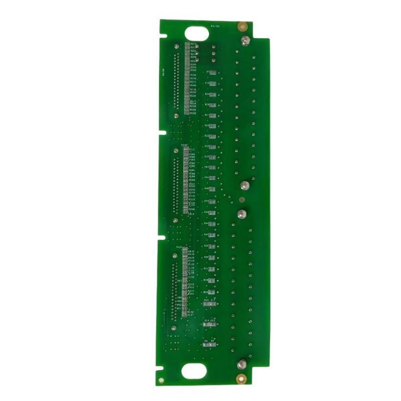
- GE
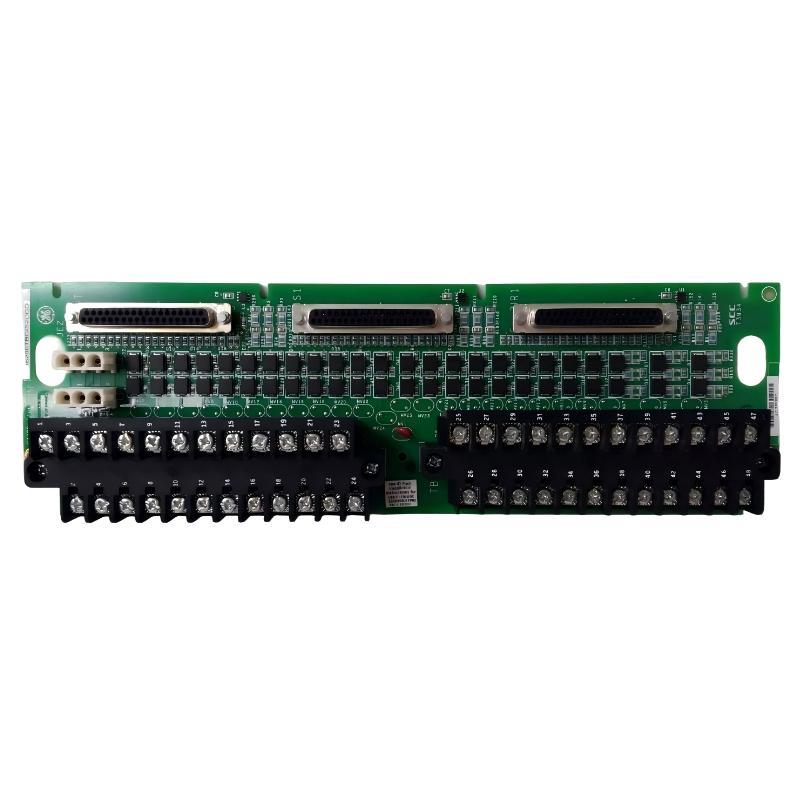
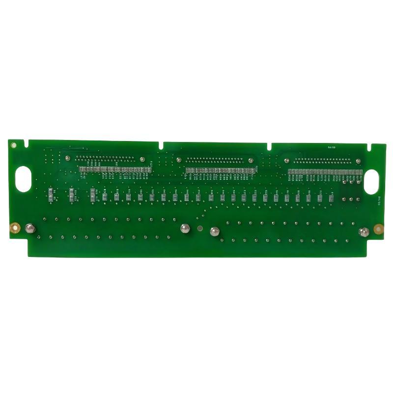
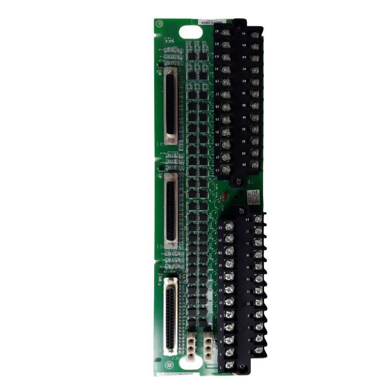
- IS200TBC1H1BCE
- Mark VI Contact Terminal Block
- USA
- 159 x 30 x 178 mm
- 0.66 kg
- Xiamen, China
- New & In Stock
- T/T, PayPal, Western Union
- 1 Year
- 1-3 Working Days
- DHL, UPS, TNT, FedEx and EMS.
- 24-Hour Service
- COO
- 8
Our advantage

Global Logistics
We have a 10-year logistics and express cooperation agreement, so our products can be shipped to any place in the world.

Brand new and original
Our products are imported in bulk from the place of origin. Because of the cooperative relationship, our products are all original and 100% new.

24-hour service
We provide 7*24 hours service to our customers. We will be there whenever you need us.

Price advantage
All our products are priced very favorably because we have our own warehouse and supply.
| Company Information | |||
| [email protected] | |||
| Mobile | +8615980777398 | ||
| +8615980777398 | |||
| 15980777398 |
Product Overview
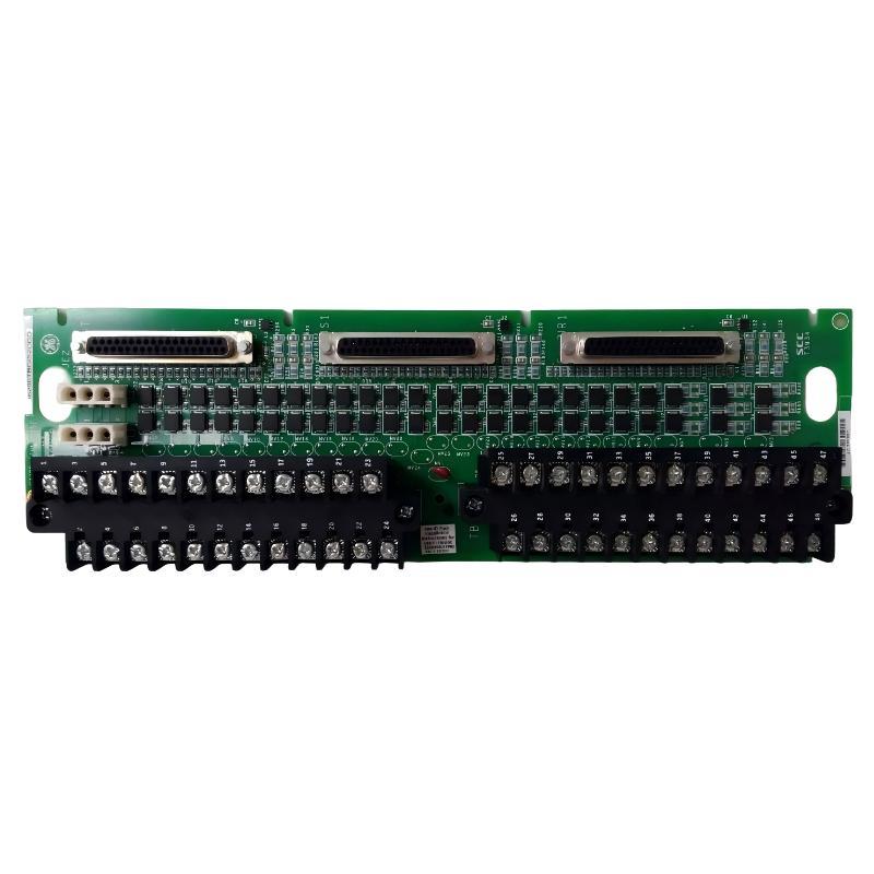
The GE IS200TBC1H1BCE Mark VI Contact Terminal Block is an industrial interface component designed for use within compatible GE Mark VI control systems. As part of the IS200 family of industrial control hardware, the terminal block provides an organized connection point between field wiring and the control system electronics. It helps simplify signal termination, wiring management, inspection, and maintenance in industrial automation environments.
Terminal blocks play an important role in distributed control architectures because they provide a practical interface between field devices and electronic control boards. Instead of connecting numerous field conductors directly to sensitive control electronics, a terminal block can provide a structured termination point that improves wiring organization and facilitates troubleshooting.
The GE IS200TBC1H1BCE has listed dimensions of 159 × 30 × 178 mm and a weight of approximately 0.66 kg. Its compact form factor allows it to be integrated into industrial control cabinets and equipment assemblies where space, wiring accessibility, and reliable field connections are important considerations.
The IS200TBC1H1BCE is particularly relevant to maintenance and replacement operations involving existing Mark VI control equipment. Correct identification of the complete board or terminal-block part number is essential because visually similar IS200 components can have different electrical functions and system interfaces.
Technical Specifications
| Parameter | Specification |
|---|---|
| Manufacturer | General Electric (GE) |
| Model | IS200TBC1H1BCE |
| Product Family | GE Mark VI / IS200 Series |
| Product Type | Contact Terminal Block |
| Application | Industrial Control and Automation |
| Interface Function | Field Wiring and Control-System Termination |
| System Compatibility | Compatible GE Mark VI control architecture |
| Dimensions | 159 × 30 × 178 mm |
| Weight | 0.66 kg |
| Installation | Industrial control cabinet / compatible Mark VI equipment |
| Primary Role | Signal termination and field interface |
| Typical Environment | Industrial automation and process control |
What Is the GE IS200TBC1H1BCE?
The IS200TBC1H1BCE is a GE Mark VI Contact Terminal Block used as part of an industrial control-system wiring architecture.
In a typical automation installation, field devices such as sensors, switches, actuators, relays, and other process instruments must exchange electrical signals with the control system. The terminal interface provides a structured point where these field connections can be terminated and routed toward the appropriate control electronics.
A simplified signal architecture can be represented as:
Field Device → Field Wiring → IS200TBC1H1BCE → Control Interface → Mark VI Controller
The exact signal arrangement depends on the host equipment and system configuration.
The terminal block itself should therefore be viewed as an important part of the overall signal infrastructure rather than as a standalone controller. Its primary value is providing an organized and serviceable electrical interface between external wiring and the control-system architecture.
Function and Working Principle
Field Wiring Termination
The primary role of a contact terminal block is to provide a defined termination point for field conductors.
Industrial control cabinets can contain a large number of cables. Without organized termination points, wiring can become difficult to trace and maintain. A properly installed terminal interface creates a structured connection between field wiring and the control system.
Signal Routing
Once field conductors are terminated, the associated signals can be routed toward the appropriate Mark VI control hardware.
Depending on the application, these signals may originate from:
- Process sensors
- Auxiliary contacts
- Status switches
- Relay circuits
- Control devices
- Monitoring circuits
- Other field instrumentation
The exact signal types and terminal assignments must be confirmed against the applicable system documentation and hardware configuration.
Wiring Organization
The IS200TBC1H1BCE can contribute to cleaner cabinet construction by separating field wiring from sensitive electronic assemblies.
Organized wiring makes it easier for technicians to:
- Identify individual circuits
- Trace signal paths
- Perform electrical testing
- Replace components
- Inspect connections
- Troubleshoot intermittent problems
Maintenance Interface
A terminal block can also act as a convenient maintenance interface. Technicians can inspect wiring connections and identify field-side problems without immediately disturbing other control-system components.
This is especially useful in large industrial installations where downtime must be minimized.
Role in GE Mark VI Control Systems
The GE Mark VI architecture is designed for industrial control and monitoring applications where reliable communication between field instrumentation, control electronics, and operator systems is required.
Within such an architecture, terminal-interface components form an important layer between the physical process and electronic control equipment.
The IS200TBC1H1BCE can therefore be considered part of the physical signal-interface infrastructure.
A simplified architecture is:
Process Equipment
↓
Field Sensors / Contacts / Devices
↓
Field Wiring
↓
IS200TBC1H1BCE Contact Terminal Interface
↓
Mark VI I/O and Control Electronics
↓
Controller / Control Logic
↓
HMI / Operator Interface / Supervisory System
This structure allows field information to be transferred into the control system in an organized manner.
Importance of Terminal Interfaces in Industrial Automation
Terminal interfaces are often overlooked compared with processors, communication modules, and I/O boards, but they are essential to reliable industrial control systems.
A control system can only operate correctly when field signals reach the appropriate electronic inputs and control outputs are correctly transferred to field devices.
Poor termination can lead to:
- Intermittent signals
- Open circuits
- Incorrect status indications
- Unexpected alarms
- Difficult troubleshooting
- Increased maintenance time
- Unplanned equipment downtime
A properly maintained terminal interface helps reduce these risks by providing a stable and organized connection point.
Industrial Applications
Turbine Control
GE Mark VI systems are associated with turbine and generator control applications. Terminal interfaces can be used within the broader control-system wiring infrastructure to connect field devices and auxiliary circuits with control electronics.
Power Generation
Power-generation facilities contain extensive instrumentation and electrical monitoring systems. Terminal blocks help organize the wiring associated with sensors, switches, status signals, and control circuits.
Industrial Process Control
The same type of field-interface architecture can be used in industrial process-control installations where numerous instruments must be connected to centralized or distributed control electronics.
Equipment Monitoring
Field contacts and monitoring devices can provide information about equipment operating conditions. A structured terminal interface simplifies the physical connection between these devices and the control system.
Plant Automation
Large industrial plants often contain hundreds or thousands of field conductors. Proper terminal organization becomes increasingly important as the scale of the automation system increases.
Installation and System Integration
Correct installation of the GE IS200TBC1H1BCE is important for reliable signal transmission and long-term serviceability.
Verify Part Number
Before installation or replacement, confirm:
- Complete part number
- Board or terminal-block identification
- Revision designation
- Existing installation location
- Connector arrangement
- Field wiring configuration
- Associated Mark VI hardware
The complete IS200TBC1H1BCE designation should be matched rather than relying only on physical appearance.
Inspect Existing Wiring
Before removing an existing terminal interface, technicians should document the field wiring arrangement.
Useful information includes:
- Wire numbers
- Terminal positions
- Cable identification
- Signal names
- Shield connections
- Ground connections
- Associated I/O channels
Photographs and wiring records can also help prevent incorrect reconnection.
Mechanical Installation
The terminal block should be securely mounted in the designated equipment location.
The listed dimensions are:
159 × 30 × 178 mm
Adequate clearance should be maintained to allow:
- Cable access
- Inspection
- Connector handling
- Ventilation where applicable
- Future maintenance
Electrical Connections
Field conductors should be connected according to the applicable Mark VI wiring documentation.
Before energizing the system, technicians should verify:
- Correct wire location
- Secure termination
- Correct polarity where applicable
- Proper grounding
- Correct shielding
- Absence of accidental shorts
The exact terminal assignments should not be assumed from physical appearance alone.
Cabinet Wiring and Cable Management
Good cabinet wiring practices are particularly important when terminal blocks are installed alongside high-density I/O and control electronics.
Field cables should be routed in an organized manner and separated from sources of significant electrical interference where appropriate.
Recommended practices include:
- Keep wiring clearly labeled.
- Maintain consistent cable routing.
- Avoid excessive conductor bending.
- Secure cables to prevent mechanical strain.
- Keep signal wiring separated from high-power conductors where appropriate.
- Maintain clean cabinet pathways.
- Avoid loose wires near electronic assemblies.
- Verify shield and grounding arrangements.
These practices can improve serviceability and reduce the possibility of signal interference.
Grounding and Shielding Considerations
Industrial control systems may contain sensitive measurement and communication circuits that can be affected by electrical noise.
Grounding and shielding should therefore follow the requirements of the complete Mark VI installation.
Potential sources of interference include:
- Variable frequency drives
- Motors
- Contactors
- High-current switching equipment
- Power converters
- Large transformers
- Relay circuits
Signal cables should be routed appropriately to minimize unwanted coupling.
The terminal block should not be treated as an independent grounding solution. Grounding and shielding must be considered as part of the complete cabinet and control-system design.
PLC, Controller and I/O Integration
Although the IS200TBC1H1BCE is a terminal interface rather than a programmable controller, it participates in the physical signal chain used by the control system.
A typical control sequence may be:
- A field device detects a process condition.
- The electrical signal travels through field wiring.
- The signal reaches the terminal interface.
- The associated I/O electronics receive the signal.
- The Mark VI control system processes the information.
- Control logic determines the required response.
- The appropriate output or control command is generated.
- The field equipment responds.
This architecture allows the terminal interface to support the reliable movement of information between field equipment and control electronics.
HMI and Supervisory System Integration
The terminal block does not normally provide HMI functionality itself. Instead, it forms part of the field-level connection infrastructure.
Once a field signal reaches the appropriate control and I/O electronics, the processed information can be made available to higher-level systems.
Depending on the overall installation, operators may use the control system to monitor:
- Equipment status
- Process conditions
- Alarm states
- Interlock conditions
- Field-device status
- Operating parameters
Therefore, a problem at the terminal-interface level can potentially appear to an operator as an abnormal input, missing status signal, or unexpected alarm.
Commissioning Procedure
A systematic commissioning process can reduce wiring-related problems.
Step 1: Verify Identification
Confirm that the installed component matches the required IS200TBC1H1BCE part number and applicable system configuration.
Step 2: Inspect Mechanical Installation
Check that the terminal block is securely mounted and that there is no visible mechanical damage.
Step 3: Verify Wiring
Compare every relevant conductor against the approved wiring documentation.
Step 4: Check Connections
Inspect terminals and connectors for looseness, contamination, corrosion, or physical damage.
Step 5: Verify Grounding
Confirm that grounding and shielding connections follow the installation requirements.
Step 6: Perform Signal Verification
Check the associated field signals under known operating conditions.
Step 7: Check Control-System Diagnostics
Review the Mark VI system for abnormal input states, communication problems, alarms, or other diagnostic indications.
Step 8: Return to Service
After all checks have been completed, return the equipment to normal operation according to the applicable plant procedure.
Troubleshooting the IS200TBC1H1BCE
Terminal-interface faults should be investigated as part of the complete field-to-controller signal path.
No Signal at the Control System
If an expected field signal is missing, inspect:
- Field device
- Field cable
- Terminal connection
- Terminal-block connectors
- Associated I/O hardware
- Control-system diagnostics
- Grounding and shielding
A missing signal does not automatically indicate that the terminal block has failed.
Intermittent Signal
Intermittent behavior may be caused by:
- Loose terminal connections
- Damaged wiring
- Connector problems
- Vibration
- Corrosion
- Mechanical cable strain
- Electrical interference
- Field-device problems
Monitoring the signal while inspecting the wiring can help identify intermittent faults.
Incorrect Status Indication
If the control system reports an unexpected device status, verify the complete signal path.
Possible causes include:
- Incorrect wiring
- Wrong terminal position
- Field-device failure
- Incorrect configuration
- Loose connection
- I/O hardware problem
Multiple Signals Affected
If several related signals fail simultaneously, technicians should investigate common elements such as:
- Shared wiring
- Common termination points
- Associated connectors
- I/O interface hardware
- Power or reference connections
- System configuration
A multiple-signal failure can provide useful information about the location of the fault.
Preventive Maintenance
Regular inspection can improve the reliability of terminal interfaces.
Visual Inspection
Check for:
- Cracked components
- Discoloration
- Loose hardware
- Damaged connectors
- Contamination
- Signs of overheating
- Corrosion
Wiring Inspection
Inspect field conductors for:
- Broken insulation
- Loose terminals
- Mechanical strain
- Improper routing
- Moisture exposure
- Incorrect labeling
Connection Verification
Connections should remain secure throughout the service life of the equipment.
Where plant procedures permit, maintenance personnel can periodically verify connection integrity during scheduled shutdowns.
Environmental Control
Industrial cabinets should be maintained within the environmental conditions required by the overall control system.
Excessive:
- Heat
- Moisture
- Dust
- Vibration
- Chemical contamination
can contribute to premature degradation of electrical components and connections.
Replacement and Spare-Part Planning
When replacing a GE IS200TBC1H1BCE, the complete identification should be verified before installation.
Important information includes:
- Full model number
- Revision
- Board markings
- Physical dimensions
- Connector arrangement
- Existing wiring configuration
- Host Mark VI equipment
- Associated I/O hardware
The listed dimensions are:
159 × 30 × 178 mm
The listed weight is:
0.66 kg
These physical specifications can also assist with inventory management, shipping preparation, cabinet planning, and spare-part identification.
A visually similar GE IS200 component should not automatically be considered an interchangeable replacement.
Physical Dimensions and Weight
The GE IS200TBC1H1BCE has listed dimensions of:
159 × 30 × 178 mm
Its listed weight is:
0.66 kg
The relatively compact dimensions allow the terminal interface to be installed within industrial control cabinets while providing an organized connection point for field wiring.
For replacement planning, both physical dimensions and connector arrangement should be considered together with the electrical and system requirements.
Compatible System Components
The IS200TBC1H1BCE may form part of a broader GE Mark VI control architecture containing components such as:
| Component | General Function |
|---|---|
| Mark VI Controller | Executes control logic |
| Mark VI I/O Hardware | Interfaces with process signals |
| IS200 Terminal Interface | Provides field wiring termination |
| Field Sensors | Measure process conditions |
| Field Switches | Provide discrete status signals |
| Relays | Perform switching functions |
| Control Cabinet | Houses control-system hardware |
| HMI / Operator Interface | Displays process and equipment information |
| Engineering Workstation | Supports configuration and diagnostics |
The exact combination depends on the host equipment and plant configuration.
Recommended Related GE Models
| GE Model | Product Description | General Role |
|---|---|---|
| IS200STAIH2ACB | Analog I/O Terminal Block | Analog field-signal interface |
| IS200SSCAH2AGD | Serial Communication I/O Terminal Board | Communication and I/O interface |
| IS200ECTBG1ADA | Exciter Contact Terminal Block | Excitation-system field interface |
| IS200ECTBG1ADE | Exciter Contact Terminal Block | Excitation-system termination |
| IS200EBKPG1CAA | Exciter Backplane | Control-board interconnection |
| IS200EMIOH1ACA | Excitation Control Board | Excitation control interface |
| IS200ERIOH1AAA | Excitation Regulator I/O Board | I/O and regulator interface |
These components represent related GE industrial control assemblies. They should not be treated as direct replacements for the IS200TBC1H1BCE without confirming the complete system configuration and hardware requirements.
Engineering Best Practices
For reliable operation of the IS200TBC1H1BCE, several engineering practices are recommended.
Maintain Accurate Wiring Documentation
Keep terminal assignments, cable identification, and field-device information up to date.
Use Clear Cable Labels
Every field conductor should have an identifiable reference corresponding to the engineering documentation.
Separate Signal and Power Wiring
Where appropriate, maintain physical separation between sensitive signal cables and high-power conductors.
Record Maintenance Changes
Any wiring modification should be documented so that future technicians can accurately understand the installation.
Keep Spare Identification Information
When stocking a replacement terminal interface, record the complete model number and revision information.
Avoid Unverified Substitution
Do not replace an IS200 terminal component solely because another component has similar dimensions or connector appearance.
Key Advantages
Organized Field Wiring
The IS200TBC1H1BCE provides a structured interface for field connections within compatible GE Mark VI systems.
Improved Serviceability
Organized termination makes inspection, signal tracing, and maintenance easier.
Compact Construction
With dimensions of 159 × 30 × 178 mm, the component can be integrated into industrial control equipment where cabinet space is important.
Reliable Signal Infrastructure
A properly installed terminal interface supports stable communication between field wiring and associated control electronics.
Simplified Troubleshooting
Clearly organized field connections can make it easier to isolate wiring, sensor, and I/O problems.
Mark VI System Integration
The terminal block can form part of the physical signal-interface architecture of compatible GE Mark VI installations.
Technical FAQs
What is the GE IS200TBC1H1BCE?
The GE IS200TBC1H1BCE is a Mark VI Contact Terminal Block designed for field-wiring termination and signal-interface applications within compatible GE industrial control systems.
What is the primary function of the IS200TBC1H1BCE?
Its primary function is to provide an organized connection point between field wiring and associated control-system electronics.
What are the dimensions of the IS200TBC1H1BCE?
The listed dimensions are 159 × 30 × 178 mm.
How much does the IS200TBC1H1BCE weigh?
The listed weight is approximately 0.66 kg.
Is the IS200TBC1H1BCE a controller?
No. It is a Contact Terminal Block, not a general-purpose controller or processor.
Can the IS200TBC1H1BCE be used with any GE Mark VI system?
Compatibility should be verified against the specific Mark VI equipment, wiring configuration, revision, and associated I/O hardware. The same physical family does not automatically mean that every component is interchangeable.
What can cause a signal problem at the terminal block?
Potential causes include loose wiring, damaged field cables, incorrect termination, connector problems, field-device faults, electrical interference, or problems elsewhere in the I/O signal path.
Why is correct terminal identification important?
Incorrect terminal identification can result in signals being connected to the wrong circuits, causing abnormal readings, unexpected alarms, or control-system faults.
How should the IS200TBC1H1BCE be maintained?
Maintenance should include visual inspection, wiring inspection, connector checks, environmental inspection, and verification of field signals according to the applicable plant maintenance procedures.
Should the exact revision be checked before replacement?
Yes. The complete IS200TBC1H1BCE identification and applicable revision should be checked before replacing an installed component.
Conclusion
The GE IS200TBC1H1BCE Mark VI Contact Terminal Block is an important field-interface component for compatible GE industrial control architectures. By providing an organized termination point between field wiring and control-system electronics, it supports reliable signal routing, improved cabinet organization, easier maintenance, and more efficient troubleshooting.
With listed dimensions of 159 × 30 × 178 mm and a weight of 0.66 kg, the IS200TBC1H1BCE provides a compact terminal-interface solution suitable for industrial control equipment where reliable field connections are essential.
For installation, maintenance, and replacement work, technicians should verify the complete IS200TBC1H1BCE part number, revision, connector arrangement, wiring configuration, and host-system requirements. Proper documentation, secure field connections, appropriate cable routing, and systematic commissioning are essential for maintaining dependable operation of the overall Mark VI control system.