

ProductPRODUCT
Featured products
Contact Us
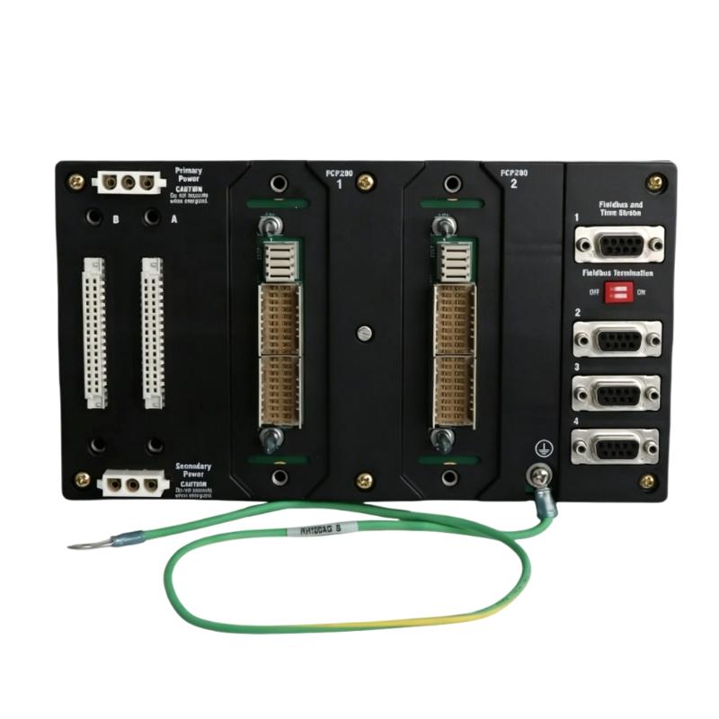
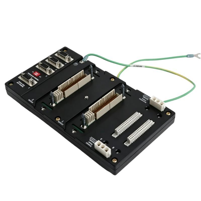
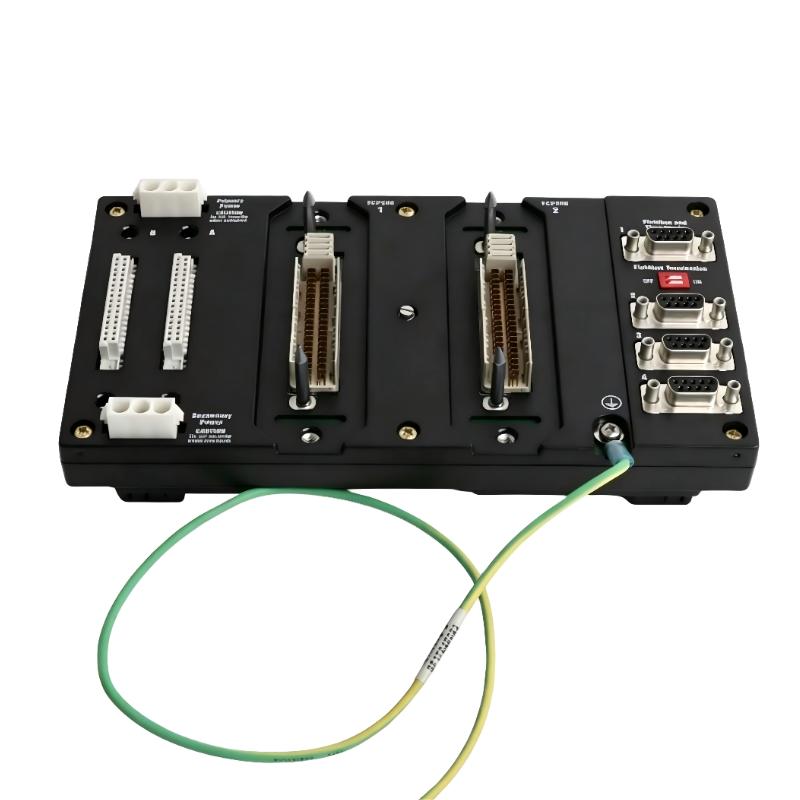
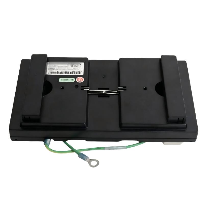
- Foxboro
- FCP280 RH924YF
- Vertical Mount Base Plate
- USA
- 150 x 35 x 110 mm
- 0.35 kg
- Xiamen, China
- New & In Stock
- T/T, PayPal, Western Union
- 1 Year
- 1-3 Working Days
- DHL, UPS, TNT, FedEx and EMS.
- 24-Hour Service
- COO
- 49
Our advantage

Global Logistics
We have a 10-year logistics and express cooperation agreement, so our products can be shipped to any place in the world.

Brand new and original
Our products are imported in bulk from the place of origin. Because of the cooperative relationship, our products are all original and 100% new.

24-hour service
We provide 7*24 hours service to our customers. We will be there whenever you need us.

Price advantage
All our products are priced very favorably because we have our own warehouse and supply.
| Company Information | |||
| [email protected] | |||
| Mobile | +8615980777398 | ||
| +8615980777398 | |||
| 15980777398 |
Product Overview
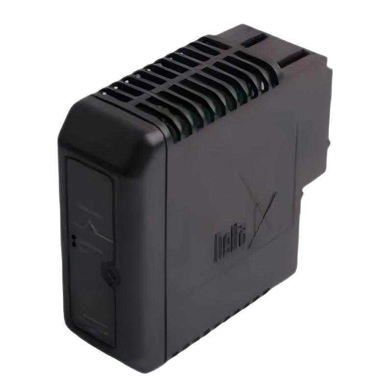
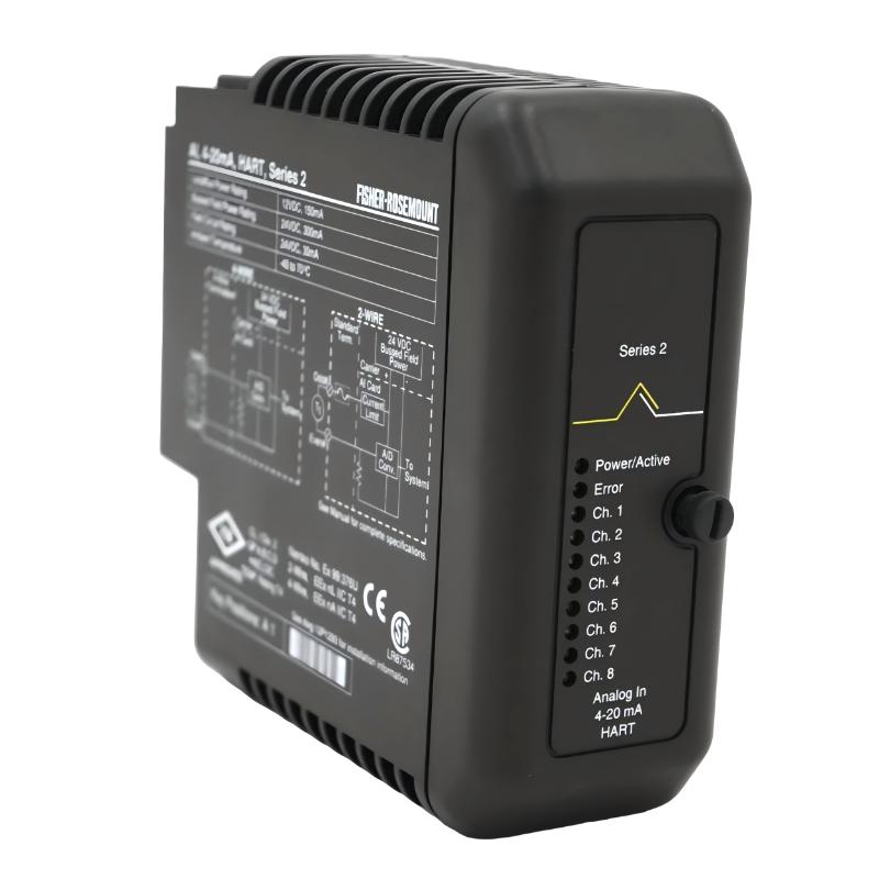
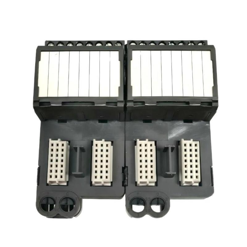
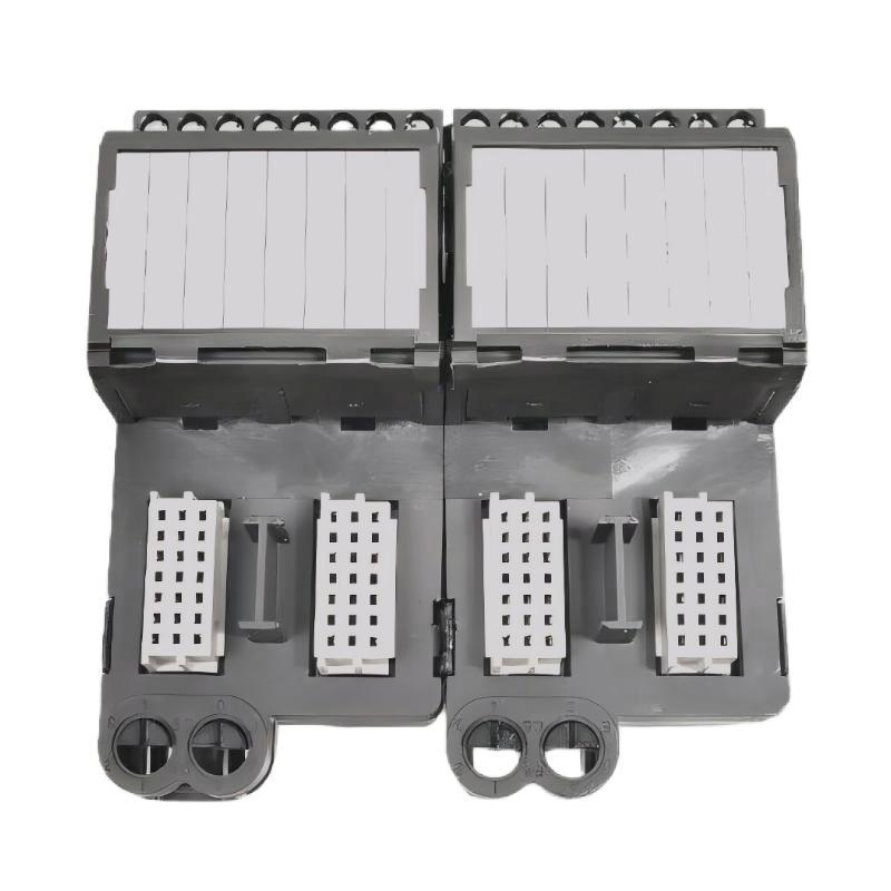
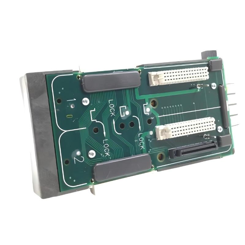
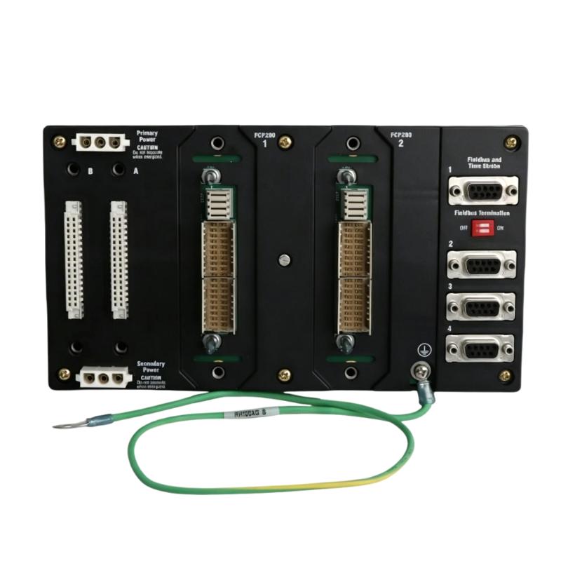
The Foxboro FCP280 RH924YF Vertical Mount Baseplate is a dedicated mounting and interconnection baseplate designed for the Foxboro FCP280 Field Control Processor. It provides the mechanical mounting structure and electrical interfaces required to integrate an FCP280 controller into a distributed control system.
The RH924YF is intended for vertical DIN-rail mounting and is suitable for industrial control cabinets where the controller needs to be installed in a vertical orientation. The baseplate supports the installation of FCP280 controllers together with compatible network adapters and fieldbus connections.
The baseplate itself is not an active CPU or I/O module. It does not execute control logic, process analog signals, or perform calculations. Instead, it provides the infrastructure through which the FCP280 processor connects to fieldbus networks, control-network equipment, power, and associated system components.
The RH924YF uses a two-position architecture, allowing it to accommodate a single FCP280 processor in a standard configuration or two FCP280 processors in a fault-tolerant configuration.
The supplied product dimensions are 150 × 35 × 110 mm, with an approximate weight of 0.35 kg.
Technical Specifications
| Parameter | Specification |
|---|---|
| Manufacturer | Foxboro |
| Model | RH924YF |
| Associated Controller | FCP280 |
| Product Type | Vertical Mount Baseplate |
| Mounting Method | DIN Rail |
| Mounting Orientation | Vertical |
| Controller Positions | 2 |
| Single Controller Configuration | Supported |
| Fault-Tolerant Configuration | Supported |
| Fieldbus Architecture | HDLC-Based Fieldbus |
| Fieldbus Channels | Up to 4 |
| Network Adapter Positions | 2 |
| Application | Foxboro DCS |
| Installation | Industrial Control Cabinet |
| Dimensions | 150 × 35 × 110 mm |
| Weight | 0.35 kg |
| Primary Function | Controller Mounting and Electrical Interconnection |
Function and Working Principle
The RH924YF provides the physical interface between the FCP280 processor and the surrounding control-system infrastructure.
A typical arrangement can be represented as:
Field Instruments
↓
Fieldbus Modules
↓
Fieldbus Network
↓
RH924YF Baseplate
↓
FCP280 Processor
↓
Network Adapter
↓
DCS Control Network
↓
Operator and Engineering Systems
The FCP280 performs the actual control processing, while the RH924YF provides the mounting and interconnection platform.
This means the baseplate is critical to system reliability even though it does not contain active control electronics.
A poor connection between the processor and baseplate can cause symptoms such as:
- Controller communication loss
- Fieldbus communication failure
- Intermittent controller operation
- Network connection problems
- Redundancy faults
- Unexpected controller resets
Therefore, the RH924YF should be considered an important part of the FCP280 hardware architecture during installation and maintenance.
Two-Position Controller Architecture
The RH924YF provides two FCP280 mounting positions.
Single FCP280 Configuration
For a standard controller installation:
Position 1 → FCP280
Position 2 → Unused
This configuration uses one active controller.
It is appropriate when controller redundancy is not required or when the application uses a single control processor.
Fault-Tolerant Configuration
For applications requiring increased controller availability:
Position 1 → FCP280 Primary
Position 2 → FCP280 Secondary
The two processors form a fault-tolerant controller arrangement.
This type of configuration can be useful in:
- Continuous-process plants
- Oil and gas facilities
- Chemical plants
- Refining systems
- Power-generation facilities
- Critical utility systems
The complete redundant architecture must be configured correctly. Installing two processors on the baseplate alone does not guarantee proper fault-tolerant operation.
Fieldbus Integration
The RH924YF supports the FCP280 fieldbus architecture.
The FCP280 system can communicate with distributed Fieldbus Modules through multiple fieldbus channels.
A simplified architecture is:
FCP280
├── Fieldbus Channel 1
├── Fieldbus Channel 2
├── Fieldbus Channel 3
└── Fieldbus Channel 4
The fieldbus channels can connect the FCP280 to distributed I/O located throughout a process plant.
This distributed arrangement reduces the need to bring every field signal directly into a central control cabinet.
For example:
Pressure Transmitter
→ Analog Input FBM
→ Fieldbus
→ FCP280
→ Control Algorithm
→ Output FBM
→ Control Valve
The baseplate provides the physical connection between the processor and the fieldbus infrastructure.
Network Integration
The FCP280 can communicate with the wider DCS through compatible network adapters installed on the baseplate.
Depending on the system architecture, the installation may use:
- Fiber-optic communication
- Copper Ethernet communication
- Redundant network connections
The RH924YF provides the physical mounting arrangement for compatible network adapters.
The network adapter selection should be based on:
- DCS network architecture
- Required communication medium
- Cabinet arrangement
- Network redundancy
- Cable distance
- Electrical environment
Installation Guide
1. Verify the RH924YF
Before installation, confirm:
- Correct model number
- Correct FCP280 compatibility
- Vertical mounting requirement
- Correct baseplate configuration
- Required network adapters
- Required fieldbus accessories
- Suitable cabinet dimensions
The RH924YF should not be substituted with another baseplate solely because the alternative appears mechanically similar.
2. Inspect the Baseplate
Before mounting, inspect the RH924YF for:
- Cracks
- Broken mounting components
- Damaged connectors
- Bent terminals
- Contamination
- Corrosion
- Signs of impact
- Damaged electrical contacts
If significant physical damage is present, the baseplate should not be installed.
3. Prepare the DIN Rail
The RH924YF is designed for vertical DIN-rail installation.
Before installation:
- Confirm the DIN rail is securely mounted.
- Verify that it is correctly aligned.
- Check available cabinet space.
- Confirm sufficient clearance around the processor.
- Provide adequate space for network and fieldbus cables.
- Make sure adjacent equipment does not obstruct the baseplate.
4. Mount the Baseplate
Position the RH924YF on the DIN rail.
Secure the baseplate according to the cabinet mounting arrangement.
After installation, verify that:
- The baseplate is firmly attached.
- It does not move excessively.
- The orientation is correct.
- The processor position is accessible.
- Network adapters can be installed.
- Fieldbus connectors can be reached easily.
5. Connect Power
Connect the appropriate DC power wiring according to the system design.
Before applying power:
- Verify polarity.
- Check voltage.
- Inspect wiring.
- Tighten connections.
- Verify protective devices.
- Check for accidental shorts.
Incorrect power wiring can damage connected equipment.
6. Connect Fieldbus Wiring
Connect the fieldbus cables to the appropriate channels.
Check:
- Channel identification
- Cable polarity
- Connector seating
- Shielding
- Cable routing
- Termination
- Mechanical strain
Avoid routing fieldbus cables in a manner that places continuous mechanical pressure on the baseplate connectors.
7. Install the FCP280 Processor
Install the FCP280 processor into the appropriate position on the RH924YF.
Before insertion:
- Confirm the module is the correct type.
- Inspect the processor connector.
- Check the baseplate connector.
- Make sure no foreign material is present.
Insert the processor carefully and secure it according to the equipment design.
Do not force the processor into the baseplate.
8. Install Network Adapters
Install the required network adapter or adapters.
The exact arrangement depends on the DCS network design.
Check:
- Adapter compatibility
- Correct position
- Connector seating
- Network cable type
- Network cable routing
9. Connect the Control Network
Connect the Ethernet or fiber-optic network according to the system architecture.
Inspect:
- Network cable
- Connector
- Adapter
- Network switch
- Link status
- Cable routing
10. Verify the Complete Installation
Before commissioning, perform a complete inspection.
| Item | Verification |
|---|---|
| RH924YF | Correct model |
| DIN Rail | Secure |
| FCP280 | Correctly seated |
| Power | Correct voltage and polarity |
| Fieldbus | Correct connections |
| Network Adapter | Correct installation |
| Network | Correct connection |
| Cabinet | Adequate clearance |
| Wiring | Secure and correctly routed |
| Redundancy | Correct configuration |
Commissioning Procedure
Once the physical installation is complete, commission the system systematically.
Step 1: Energize the System
Apply the required power.
Step 2: Check Controller Status
Verify that the FCP280 starts correctly.
Step 3: Check Network Communication
Confirm communication between the controller and the DCS network.
Step 4: Check Fieldbus Communication
Verify that fieldbus channels are operating normally.
Step 5: Check Fieldbus Modules
Confirm that the expected FBMs are available.
Step 6: Verify I/O
Check that field values correspond to the correct process signals.
Step 7: Verify Control Loops
Check:
- Process variables
- Setpoints
- Controller outputs
- PID operation
- Alarm limits
Step 8: Test Interlocks
Verify equipment permissives and protective interlocks.
Step 9: Test Alarms
Confirm that configured alarms are generated and displayed correctly.
Step 10: Verify Redundancy
For a redundant installation, confirm that both FCP280 controllers operate correctly and that the standby processor is available.
Troubleshooting Guide
FCP280 Does Not Start
If the processor does not start, check the common infrastructure first.
Possible causes include:
- No DC power
- Incorrect power polarity
- Loose wiring
- Poor processor seating
- Damaged baseplate connector
- Processor hardware failure
Troubleshooting Procedure
- Measure the power supply.
- Verify polarity.
- Check power terminals.
- Inspect the processor.
- Inspect the RH924YF connector.
- Reseat the processor if appropriate.
- Review controller diagnostics.
FCP280 Is Not Recognized
If the DCS cannot recognize the processor:
Check the Baseplate
Inspect the mechanical connection between the processor and RH924YF.
Check the Network Adapter
Verify that the network adapter is correctly installed.
Check Network Cabling
Inspect the communication cable and network connection.
Check Configuration
Verify that the controller identity and system configuration are correct.
Fieldbus Communication Failure
If several FBMs become unavailable simultaneously, investigate common infrastructure.
Possible causes include:
- Fieldbus cable failure
- Baseplate connection problem
- Controller communication failure
- Incorrect termination
- Fieldbus power problem
- Network configuration problem
If only one FBM is affected, investigate that specific FBM and its local connection first.
One Fieldbus Channel Is Offline
When one fieldbus channel fails while other channels continue operating:
- Check the corresponding fieldbus cable.
- Check the connector.
- Verify termination.
- Check channel configuration.
- Inspect connected FBMs.
- Review FCP280 diagnostics.
A single-channel failure does not necessarily indicate a defective RH924YF.
Network Communication Failure
If the FCP280 cannot communicate with the DCS network, inspect:
- Network adapter
- Network cable
- Fiber connection if applicable
- Ethernet switch
- Network port
- Controller configuration
- Power supply
If multiple controllers on the same network become unavailable simultaneously, investigate the common network infrastructure.
Redundant Controller Problem
If the system uses two FCP280 processors and redundancy is not operating correctly, inspect:
- Both processors
- RH924YF baseplate
- Processor seating
- Power supply
- Network adapters
- Fieldbus connections
- Controller configuration
A redundancy problem should not automatically be attributed to one processor.
Intermittent Faults
Intermittent problems are often more difficult to diagnose because the system may appear normal during inspection.
Potential causes include:
- Loose connector
- Mechanical vibration
- Cable movement
- Poor termination
- Power fluctuation
- Damaged contact
- Excessive cabinet temperature
- Network interference
A useful diagnostic approach is to record when the fault occurs and determine whether it affects:
- One controller
- Both redundant controllers
- One fieldbus
- Multiple fieldbuses
- One network path
- The entire control system
The fault pattern can help identify whether the problem is local or common to the infrastructure.
Maintenance Recommendations
The RH924YF should be included in periodic maintenance inspections.
| Inspection Item | Recommended Check |
|---|---|
| Baseplate | Inspect for physical damage |
| DIN Rail | Check mounting stability |
| Processor | Verify secure seating |
| Connectors | Inspect contacts |
| Power | Check voltage and wiring |
| Fieldbus | Inspect cables and termination |
| Network | Check communication connections |
| Cabinet | Check temperature |
| Ventilation | Verify airflow |
| Wiring | Check for mechanical stress |
| Grounding | Verify system grounding |
| Diagnostics | Review recurring faults |
Because the RH924YF is part of the controller’s physical interconnection system, a deteriorated baseplate can create faults that appear to originate from the FCP280 processor.
Industrial Applications
Oil and Gas
The RH924YF can be used in control cabinets supporting:
- Pump control
- Compressor control
- Pressure regulation
- Flow control
- Gas processing
- Pipeline systems
Refining
Applications may include:
- Distillation control
- Heat exchanger control
- Pump systems
- Compressor systems
- Storage systems
- Utility systems
Chemical Processing
The FCP280 architecture can control:
- Temperature
- Pressure
- Flow
- Level
- Batch sequences
- Process interlocks
Power Generation
Typical applications include:
- Cooling systems
- Water systems
- Auxiliary systems
- Fuel systems
- Process utilities
Water and Wastewater
The system can be used for:
- Pump stations
- Tank control
- Flow regulation
- Filtration
- Chemical dosing
- Water-treatment processes
Compatible Components
| Component | Function |
|---|---|
| RH924YF | Vertical FCP280 Baseplate |
| FCP280 RH924YA | Field Control Processor |
| RH924YL | Horizontal FCP280 Baseplate |
| RH100JX | Dual-Cable FCP280 Baseplate |
| RH924WA | Fiber Network Adapter |
| RH924UQ | Copper Network Adapter |
| RH924ZJ | Redundant Fieldbus Adapter |
| RH928CY | Fieldbus Splitter / Termination Device |
| RH924ZQ | Time Strobe Adapter |
| Foxboro FBMs | Distributed Field I/O |
| Ethernet Network Equipment | Control Network |
| DC Power Equipment | System Power |
RH924YF vs RH924YL
| Feature | RH924YF | RH924YL |
|---|---|---|
| Product Type | FCP280 Baseplate | FCP280 Baseplate |
| Mounting Orientation | Vertical | Horizontal |
| DIN Rail Installation | Yes | Yes |
| FCP280 Positions | 2 | 2 |
| Single Controller | Supported | Supported |
| Redundant Controller | Supported | Supported |
| Fieldbus Architecture | FCP280 Standard | FCP280 Standard |
| Main Difference | Vertical Installation | Horizontal Installation |
The primary distinction is the physical mounting orientation.
Selection should therefore be based on cabinet construction, DIN-rail arrangement, cable routing, thermal requirements, and system layout.
RH924YF vs RH100JX
The RH924YF and RH100JX should not be considered interchangeable simply because both are used with FCP280 controllers.
The RH924YF is the standard vertical mounting baseplate, while RH100JX is designed around a different dual-cable fieldbus architecture.
When replacing one baseplate with another, engineers should verify:
- Fieldbus architecture
- Cable configuration
- Mounting arrangement
- Controller compatibility
- Network connections
- Redundancy requirements
Key Advantages
- Designed for FCP280 Field Control Processors
- Vertical DIN-rail mounting
- Two processor positions
- Supports single-controller installations
- Supports fault-tolerant controller configurations
- Supports FCP280 fieldbus architecture
- Provides structured processor interconnection
- Supports compatible network adapters
- Suitable for industrial control cabinets
- Compact mechanical design
- Useful for distributed control systems
- Supports organized fieldbus wiring
- Suitable for continuous-process applications
- Dimensions: 150 × 35 × 110 mm
- Weight: 0.35 kg
Technical FAQs
What is the Foxboro FCP280 RH924YF?
The RH924YF is a vertical DIN-rail-mounted baseplate designed for the Foxboro FCP280 Field Control Processor.
Is RH924YF a CPU module?
No. RH924YF is a mounting and interconnection baseplate. The FCP280 processor performs the actual control functions.
How many FCP280 processors can be installed?
The baseplate provides two processor positions, allowing either one FCP280 or a two-processor fault-tolerant configuration.
What are the dimensions of RH924YF?
The specified dimensions are:
150 × 35 × 110 mm
What is the weight?
The supplied weight is approximately:
0.35 kg
Is RH924YF designed for vertical installation?
Yes. RH924YF is specifically intended for vertical DIN-rail mounting.
Can RH924YF be used for redundant control?
Yes. Its two-position architecture supports a fault-tolerant FCP280 controller arrangement when the complete system is configured for redundancy.
Does RH924YF process I/O signals?
No. I/O processing is performed by the FCP280 controller and associated Fieldbus Modules.
What happens if the baseplate connection is poor?
A poor connection can cause intermittent controller communication, fieldbus faults, network problems, or unexpected controller behavior.
What is the difference between RH924YF and RH924YL?
RH924YF is designed for vertical mounting, while RH924YL is designed for horizontal mounting.
Can RH924YF be replaced with any FCP280 baseplate?
No. The replacement must be compatible with the required mounting orientation, fieldbus architecture, network configuration, and cabinet design.
What should be checked before replacing RH924YF?
Verify:
- Part number
- FCP280 compatibility
- Mounting orientation
- DIN-rail arrangement
- Fieldbus configuration
- Network adapters
- Power wiring
- Redundancy requirements
- Cabinet dimensions
- Existing system configuration
Conclusion
The Foxboro FCP280 RH924YF Vertical Mount Baseplate is an important infrastructure component for FCP280 distributed control systems. It provides the mechanical mounting and electrical interconnection required to install FCP280 controllers in a vertical DIN-rail configuration.
With two controller positions, the RH924YF can be used for a single FCP280 installation or for a fault-tolerant controller arrangement. Its architecture also supports the fieldbus and network connections required by the FCP280 control system.
The product specified here has dimensions of 150 × 35 × 110 mm and an approximate weight of 0.35 kg.
For installation, particular attention should be paid to DIN-rail mounting, processor seating, DC power connections, fieldbus wiring, network adapters, and cabinet clearance. During troubleshooting, the RH924YF should be inspected whenever controller communication, fieldbus communication, redundancy, or intermittent hardware problems occur.
The RH924YF is especially appropriate for industrial DCS cabinets where vertical mounting, organized wiring, reliable controller interconnection, and efficient use of cabinet space are important.