

ProductPRODUCT
Featured products








Contact Us
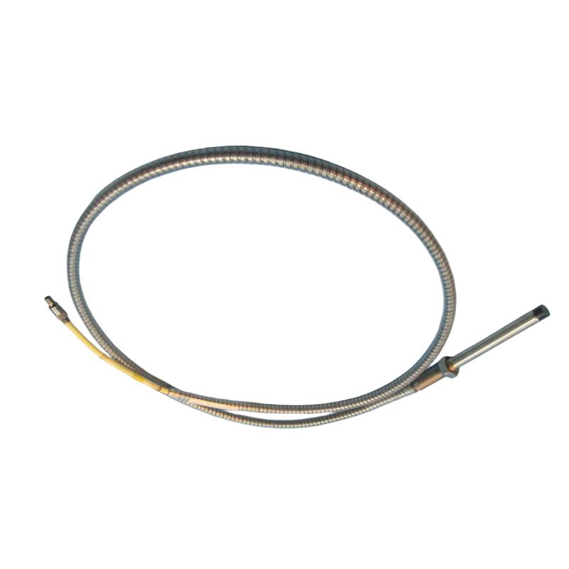
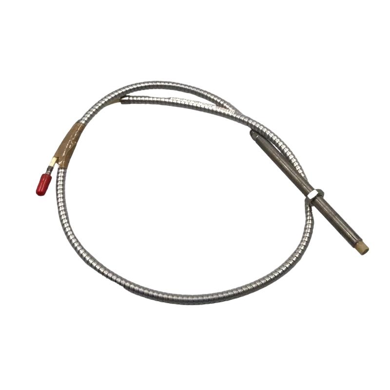
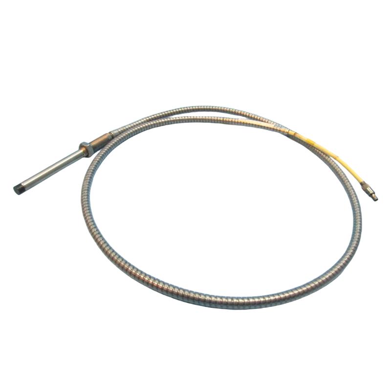
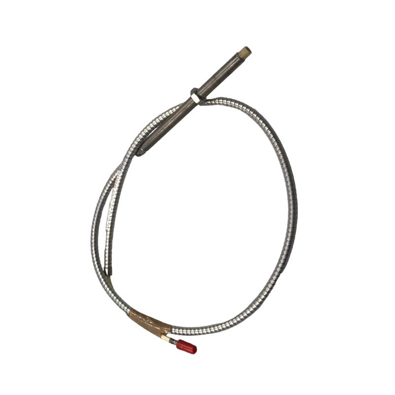
- Bently Nevada
- 21505-04-12-90-02
- 7200 Series Proximity Probe
- USA
- 9 meters
- 0.22 kg
- Xiamen, China
- New & In Stock
- T/T, PayPal, Western Union
- 1 Year
- 1-3 Working Days
- DHL, UPS, TNT, FedEx and EMS.
- 24-Hour Service
- COO
- 65
Our advantage

Global Logistics
We have a 10-year logistics and express cooperation agreement, so our products can be shipped to any place in the world.

Brand new and original
Our products are imported in bulk from the place of origin. Because of the cooperative relationship, our products are all original and 100% new.

24-hour service
We provide 7*24 hours service to our customers. We will be there whenever you need us.

Price advantage
All our products are priced very favorably because we have our own warehouse and supply.
| Company Information | |||
| [email protected] | |||
| Mobile | +8615980777398 | ||
| +8615980777398 | |||
| 15980777398 |
Product Overview
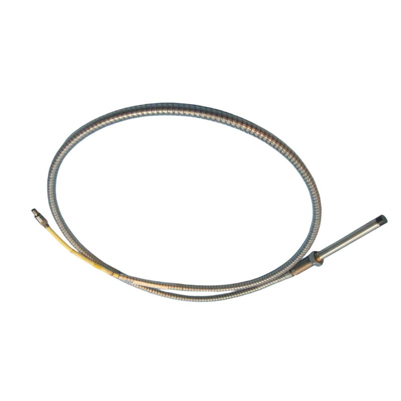
The Bently Nevada 21505-04-12-90-02 7200 Series Proximity Probe is a non-contact proximity sensor used to monitor the movement and relative position of rotating shafts. It is typically installed near the shaft of a rotating machine and connected to the associated proximity measurement electronics.
In practical machinery-monitoring systems, the probe is used where engineers need to observe shaft behavior without physically contacting the rotating surface. This makes it suitable for equipment such as steam turbines, gas turbines, compressors, pumps, generators, and other rotating machinery where shaft movement can be an important indicator of machine condition.
A proximity probe channel normally consists of more than the sensor itself. The probe works together with its associated cable, transducer electronics, monitoring equipment, and mechanical mounting arrangement. Changes in the distance between the probe tip and shaft are converted into an electrical signal that can be evaluated by the monitoring system.
The 21505-04-12-90-02 belongs to the 7200 Series. For replacement work, the exact part number should be matched with the existing monitoring channel because probe configuration, cable arrangement, and associated electronics all affect system compatibility.
Technical Specifications
| Parameter | Details |
|---|---|
| Manufacturer | Bently Nevada |
| Model | 21505-04-12-90-02 |
| Product Series | 7200 Series |
| Product Type | Proximity Probe |
| Measurement Type | Non-Contact Displacement Measurement |
| Primary Application | Rotating Machinery Monitoring |
| Measurement Target | Rotating Shaft |
| System Type | Proximity Measurement System |
| Typical Equipment | Turbines, Compressors, Pumps, Generators, Rotating Machinery |
| Installation | Fixed Position Near Rotating Shaft |
| Total Length | 9 meters |
| Weight | 0.22 kg |
Product Features
The 21505-04-12-90-02 is intended for machinery-monitoring installations where the sensor must measure shaft movement without making physical contact with the rotating component.
Key characteristics include:
- 7200 Series proximity probe
- Non-contact shaft displacement measurement
- Suitable for rotating machinery monitoring
- 9 meter total length
- Used with compatible proximity transducer electronics
- Suitable for shaft position and vibration-related monitoring
- Applicable to turbines, compressors, pumps, generators, and similar equipment
- Suitable for installations where the probe and associated measurement equipment are physically separated
The 9 meter total length is particularly relevant when planning the physical installation. Cable routing, equipment location, connection points, and protection of the cable from mechanical damage should be considered during installation.
As with other proximity measurement components, the probe should not be evaluated independently from its associated electronics. The transducer and monitoring system must be compatible with the probe configuration.
Working Principle
The probe is positioned close to the rotating shaft while remaining physically separated from it. During machine operation, any change in the shaft’s position relative to the probe changes the electrical response of the sensing circuit.
The associated transducer processes this response and produces a signal that can be used by the machinery monitoring system. Depending on the monitoring arrangement, the resulting signal can be used to observe shaft displacement, relative position, or vibration-related behavior.
For example, in a compressor or turbine, rotor movement can change as the machine passes through different operating conditions. Changes associated with thermal expansion, bearing behavior, rotor dynamics, or load can be observed through the proximity measurement channel.
The long overall connection length of this particular configuration can also affect installation planning. The cable needs to be routed carefully, secured against vibration, and protected from areas where excessive bending, abrasion, heat, or mechanical interference could damage it.
Industrial Applications
The 21505-04-12-90-02 can be used in rotating machinery applications where shaft movement needs to be monitored continuously.
| Application | Typical Use |
|---|---|
| Steam Turbines | Shaft position and rotor movement monitoring |
| Gas Turbines | Monitoring rotor behavior |
| Compressors | Shaft displacement and condition monitoring |
| Pumps | Monitoring rotating shaft movement |
| Generators | Rotor and shaft monitoring |
| Turbo Machinery | Continuous machinery condition monitoring |
| Industrial Rotating Equipment | Non-contact displacement measurement |
In large machinery installations, proximity measurements are normally considered together with other machine parameters. Bearing vibration, shaft speed, temperature, process load, and other condition-monitoring signals can help engineers determine whether an unusual reading is caused by actual mechanical movement or by an instrumentation issue.
Compatible System Components
The 21505-04-12-90-02 normally forms part of a complete proximity monitoring channel.
| Component | Function |
|---|---|
| 7200 Series Proximity Probe | Detects changes in shaft-to-probe distance |
| Proximity Transducer | Processes the probe signal |
| Probe Cable / Connection | Carries the probe signal to the associated electronics |
| Machinery Monitoring System | Receives and evaluates the measurement |
| Machinery Protection System | Provides alarm or shutdown functions where configured |
| Probe Mounting Hardware | Holds the probe in the correct physical position |
| Rotating Shaft | Provides the monitored target surface |
| Monitoring Cabinet | Houses associated monitoring electronics |
The long connection length makes cable management especially important. The cable should be routed away from sources of mechanical damage and secured so that vibration does not place unnecessary stress on the probe connection.
When replacing the probe, the associated transducer and existing cable arrangement should also be checked. A new sensor will not resolve a problem caused by damaged wiring, incorrect mounting, or incompatible monitoring electronics.
Installation and Maintenance
Installation should begin with verification of the complete probe part number and the existing monitoring-channel configuration.
Because this model has a 9 meter total length, the physical routing of the probe connection deserves particular attention. Excessive bending, unsupported cable sections, abrasion, and proximity to sources of mechanical or thermal damage can create problems during long-term operation.
Recommended checks include:
- Confirm the complete 21505-04-12-90-02 part number.
- Verify compatibility with the existing 7200 Series system.
- Check the associated transducer and connection arrangement.
- Inspect the probe tip for physical damage.
- Verify the probe mounting hardware.
- Check the probe-to-shaft installation gap.
- Route and secure the cable appropriately.
- Keep the cable away from excessive heat and mechanical interference.
- Inspect connectors for looseness or damage.
- Verify the monitoring channel after installation.
- Compare the signal with normal machine operating conditions.
- Inspect the shaft and related mechanical components if abnormal readings remain.
- Perform controlled commissioning after replacement.
If an abnormal signal occurs, technicians should inspect both the measurement chain and the machine. Incorrect probe positioning, cable damage, loose mounting, transducer problems, and actual shaft movement can produce similar symptoms.
Recommended Related Models
For this type of proximity probe, the most useful comparisons are other 7200 Series components with similar machinery-monitoring functions. Final replacement selection should be based on the complete system configuration rather than general product-family similarity.
| Model / Component | Type | Primary Function | Application |
|---|---|---|---|
| Bently Nevada 21505-04-12-90-02 | Proximity Probe | Non-contact shaft measurement | 7200 Series monitoring systems |
| Bently Nevada 21505-00-72-10-02 | Proximity Probe | Non-contact shaft measurement | 7200 Series rotating machinery |
| Bently Nevada 21505-00-60-10-02 | Proximity Probe | Non-contact shaft measurement | 7200 Series rotating machinery |
| Bently Nevada 21505-00-59-10-02 | Proximity Probe | Non-contact shaft measurement | 7200 Series rotating machinery |
| Bently Nevada 7200 Series Transducer Components | Transducer Components | Probe signal processing | Proximity monitoring channels |
The other 7200 Series probes can serve as useful comparison models when reviewing an existing installation, but similar application or series designation does not automatically establish direct interchangeability.
For a replacement project, the complete probe part number, associated electronics, connection arrangement, mounting requirements, and required measurement function should be checked before installation.
Key Advantages
- 7200 Series proximity probe
- Non-contact shaft displacement measurement
- Suitable for rotating machinery monitoring
- 9 meter total length
- Applicable to turbines, compressors, pumps, and generators
- Suitable for shaft position and vibration-related monitoring
- Works as part of a complete proximity measurement channel
- Stated weight of 0.22 kg
Technical FAQs
Why is a 9 meter probe connection useful in some machinery installations?
A longer connection can be useful when the monitored machine and associated monitoring electronics are located some distance apart. It can simplify equipment layout, but the longer routing also requires appropriate cable support and protection against mechanical or environmental damage.
Does the 9 meter length change the way the probe should be installed?
The physical installation needs more attention to cable routing and support. The connection should be secured appropriately and protected from excessive bending, abrasion, heat, and vibration while maintaining the required probe position relative to the shaft.
What should be checked if the proximity signal becomes unstable after installation?
Check the probe gap, mounting rigidity, cable routing, connectors, associated transducer, and monitoring channel. If these items are functioning normally, the next step is to compare the signal with other machine parameters to determine whether actual shaft movement is occurring.
Can the 21505-04-12-90-02 be replaced by another 7200 Series proximity probe with the same general application?
Not automatically. The replacement must be checked against the complete monitoring system, including probe configuration, associated electronics, connection arrangement, and installation requirements. Same-series designation alone is not sufficient to confirm interchangeability.