
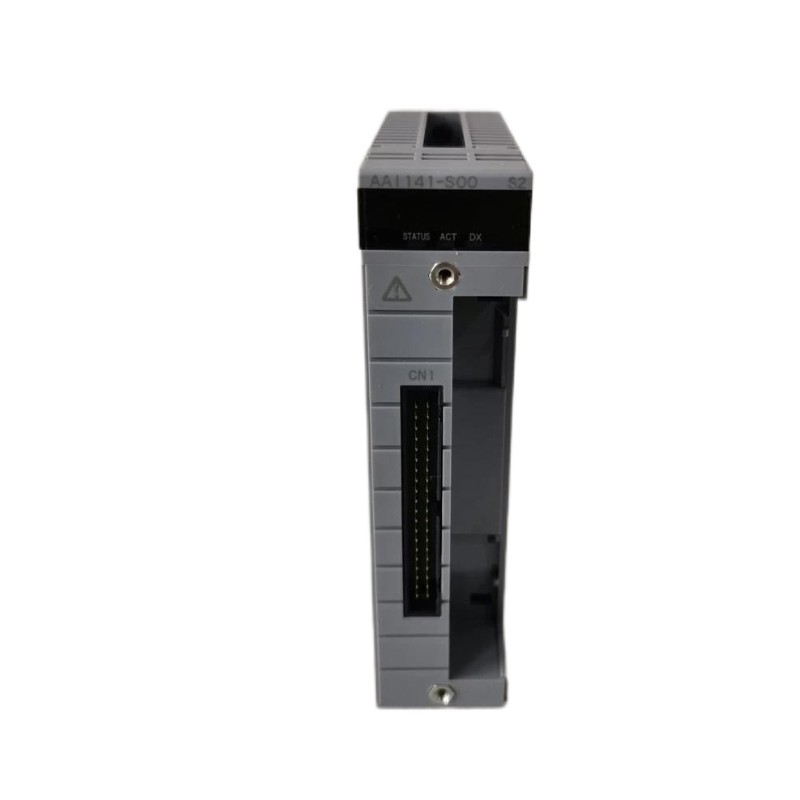
The Yokogawa AAI141-S00/K4A00 is a 16-channel, non-isolated analog input module used to acquire 4–20 mA DC signals from industrial transmitters. When a channel displays an incorrect value, remains fixed, fluctuates, or reports an abnormal status, the cause may be in the field instrument, current loop, KS cable interface, module configuration, or control-system hardware. This troubleshooting guide provides a structured approach to fault diagnosis, signal verification, module inspection, and corrective maintenance.
Contents
- AAI141-S00/K4A00 Fault Characteristics
- Common Input Fault Symptoms
- Recommended Fault Diagnosis Sequence
- 4–20 mA Signal and Wiring Checks
- Channel-Level Troubleshooting
- Module, Node, and System Diagnostics
- Illustrative Engineering Fault Scenarios
- Repair and Replacement Decisions
- Preventive Maintenance Recommendations
- Troubleshooting FAQs
- Fault Diagnosis Summary
Understanding Yokogawa AAI141-S00/K4A00 Fault Characteristics
The AAI141 converts field current signals into process data for the Yokogawa control system. It provides 16 non-isolated input channels for 4–20 mA DC signals. Its specified data update period is 10 ms, input accuracy is ±16 μA, and step response time is approximately 100 ms.
These characteristics help engineers distinguish between a field-loop problem and a system-level problem. For example, a process value that changes slowly may reflect transmitter damping or process behavior rather than an AAI141 hardware fault. Similarly, a value that is consistently incorrect may be caused by incorrect engineering scaling instead of a defective input channel.
The /K4A00 option identifies the KS cable interface adapter configuration. A loose connector, damaged cable, incorrect interface component, or poor termination can interrupt multiple input signals. Troubleshooting should therefore consider both the individual channel and the shared connection path.
Common Yokogawa AAI141 Analog Input Fault Symptoms
| Observed Symptom | Possible Cause | Initial Check |
|---|---|---|
| Input value remains at zero or below the expected range | Open loop, missing transmitter power, incorrect wiring, or inactive channel | Measure loop current and inspect wiring |
| Input value is fixed at one level | Transmitter output failure, frozen process signal, or configuration issue | Verify the field signal independently |
| Input value fluctuates | Loose termination, electrical interference, unstable transmitter, or grounding issue | Inspect wiring and compare signal at the source |
| Several channels fail simultaneously | Shared cable, interface, node, power, or configuration problem | Check common hardware and connections |
| Control-system value differs from a loop calibrator | Scaling mismatch, wiring resistance, incorrect channel assignment, or input fault | Compare current and configured engineering range |
| Module is not recognized | Incorrect slot definition, seating problem, hardware incompatibility, or node fault | Review hardware configuration and module status |
A Practical Fault Diagnosis Sequence for the AAI141-S00/K4A00
A structured diagnosis prevents unnecessary module replacement. Begin with the simplest external causes and move toward the module and system hardware only after field-side conditions have been checked.
- Identify the affected channels. Record the channel numbers, instrument tags, displayed values, alarm messages, and time when the fault began.
- Determine the fault scope. Establish whether one channel, several adjacent channels, or the entire module is affected.
- Check the field instrument. Review transmitter power, local display, diagnostic status, output configuration, and process conditions.
- Measure the current loop. Use an appropriate calibrated instrument and an approved test method to determine whether the actual signal matches the expected value.
- Inspect the field wiring. Check polarity, terminal tightness, cable continuity, shielding, and signs of moisture or corrosion.
- Inspect the KS interface path. Check the KS cable, ATK4A-00 adapter, connectors, and associated termination hardware.
- Review channel configuration. Confirm the transmitter type, input assignment, engineering range, and two-wire or four-wire setting.
- Review module and node status. Check hardware recognition, diagnostics, node condition, and power supply status.
- Perform a controlled channel test. If permitted, use a calibrated current source to determine whether the input responds correctly.
- Decide on repair or replacement. Replace the module only when external wiring, field equipment, configuration, and shared hardware have been reasonably excluded.
Checking the AAI141-S00/K4A00 4–20 mA Signal Loop
Current-loop measurement is one of the most useful diagnostic methods for analog input problems. The objective is to compare the actual current delivered to the module with the value expected from the field instrument.
Verify the transmitter output
Check the transmitter’s configured range and local indication. A pressure transmitter configured for 0–10 bar, for example, should produce a current corresponding to its actual measured pressure and configured range. If the transmitter itself reports an abnormal status, investigate the instrument before diagnosing the input module.
Measure the loop current safely
Use a calibrated meter or loop calibrator with the correct measurement range and connection method. Do not open a live loop or insert a meter in series without following the site’s approved electrical work procedure. For a live process, coordinate with operations before disconnecting any signal wiring.
Check the two-wire or four-wire arrangement
The AAI141 supports both two-wire and four-wire transmitter arrangements. An incorrect channel setting can result in a mismatch between the field wiring and the module’s expected configuration. Verify the applicable channel setting and the transmitter wiring diagram before changing connections.
Compare the current with the control-system value
For a linear 4–20 mA transmitter, the normalized percentage can be calculated as follows:
Input Percentage = (Current - 4) / 16 × 100
| Measured Current | Expected Percentage | Diagnostic Meaning |
|---|---|---|
| 4 mA | 0% | Lower range point |
| 8 mA | 25% | Low-range test point |
| 12 mA | 50% | Mid-range test point |
| 16 mA | 75% | Upper-range test point |
| 20 mA | 100% | Upper range point |
These values are illustrative. The actual control-system engineering value depends on the configured transmitter range and scaling parameters.
Troubleshooting Individual AAI141 Input Channels
One channel reads zero or an abnormally low value
Start by checking whether the transmitter is powered and producing a valid current signal. Inspect the complete loop for an open circuit, loose connection, reversed polarity, damaged conductor, or incorrect terminal assignment. If the current is correct at the transmitter but incorrect at the module input, inspect the cable and KS interface path.
One channel reads higher than expected
Compare the measured loop current with the control-system value. If the current itself is too high, inspect the transmitter range, output mode, process condition, and wiring. If the current is correct but the displayed value is high, check the configured engineering range, channel assignment, and signal conversion settings.
One channel fluctuates while others remain stable
A single-channel fluctuation often points toward a local field instrument, cable, or termination issue. Inspect the transmitter connection and the signal route. Check whether nearby variable-frequency drives, contactors, motors, or switching equipment could be introducing interference. Review shielding and grounding according to the approved site design.
Several channels become abnormal at the same time
When multiple channels fail together, look for a shared cause. The KS cable, interface adapter, terminal assembly, node hardware, or system power arrangement may affect more than one channel. Compare the affected channels with their physical wiring locations and common hardware connections.
AAI141 Module, Node, and System Diagnostics
Not every analog input fault originates in the current loop. The control-system hardware configuration and node status must also be checked, particularly when the module cannot be recognized or several input values become unavailable simultaneously.
Module recognition and slot assignment
- Confirm that the AAI141 is assigned to the correct physical slot.
- Check that the engineering configuration matches the installed module type.
- Review any module or node diagnostic indication available in the system.
- Confirm that the module is seated correctly and that its connector is not damaged.
Power supply and node condition
Review the node’s power status and the relevant power supply diagnostics. The AAI141 specification lists maximum current consumption of 310 mA at 5 V DC and 450 mA at 24 V DC. These values should be considered when checking the overall hardware power budget, but a measured supply condition must be evaluated against the actual node design and manufacturer requirements.
KS cable and interface inspection
Because the model includes the /K4A00 option, inspect the KS cable interface adapter and cable as part of the fault investigation. Check connector engagement, cable strain, damaged pins, contamination, and incorrect part selection. Avoid repeatedly disconnecting and reconnecting energized hardware unless the installed system explicitly supports that operation and the approved procedure allows it.
Channel configuration review
Compare the configured channel schedule with the field wiring drawings. Check for duplicated channel assignments, incorrect transmitter types, incorrect scaling, and mismatched two-wire or four-wire settings. A configuration error can produce a stable but incorrect value that resembles a hardware fault.
Illustrative Engineering Scenarios for AAI141 Fault Diagnosis
Scenario 1: A pressure signal remains at the lower range
Observed condition: A pressure value remains close to its lower range even though the process is operating normally.
Diagnostic approach: The engineer checks the transmitter’s local display, measures the current loop, and compares the measured current with the control-system value. The test reveals that the transmitter output is normal but the current does not reach the expected input connection.
Likely corrective action: Inspect the field cable and termination points for an open circuit or loose connection. Restore the wiring and repeat the loop test before returning the signal to service.
Scenario 2: Multiple analog values become unstable
Observed condition: Several channels connected through the same interface path show intermittent fluctuations.
Diagnostic approach: The engineer compares independent field measurements and inspects the shared KS cable and interface connections. The investigation focuses on common hardware rather than immediately replacing individual transmitters.
Likely corrective action: Correct the connector or cable problem if confirmed, then verify each affected channel independently. This is an illustrative diagnostic scenario, not a documented customer incident.
Scenario 3: The input current is correct but the displayed process value is wrong
Observed condition: A loop calibrator applies 12 mA, but the control-system display does not show the expected midpoint of the configured process range.
Diagnostic approach: The engineer confirms the applied current and checks the channel’s engineering range, unit, and instrument tag assignment.
Likely corrective action: Correct the scaling or channel configuration after verifying the approved instrument data sheet. Repeat the low-, mid-, and high-range tests.
Repair or Replacement of the Yokogawa AAI141-S00/K4A00
Repair decisions should be based on test results rather than the presence of an abnormal process value alone. The AAI141 is part of a larger signal acquisition system, so external components should be checked before the module is classified as defective.
When field wiring repair is appropriate
If the input current is missing or unstable because of a loose termination, damaged cable, incorrect polarity, or poor connection, repair the field circuit according to the approved electrical maintenance procedure. Confirm continuity and signal stability after the repair.
When configuration correction is appropriate
If the measured current is correct but the displayed engineering value is wrong, review the channel scaling, instrument range, and channel assignment. Document configuration changes and obtain the required operational approval before modifying a live control system.
When module replacement should be considered
Consider replacing the AAI141 only when the field transmitter, current loop, KS cable interface, node hardware, power supply, and configuration have been checked and the fault remains associated with the module. Before replacement, verify the full model code, suffix, option code, and system compatibility.
Replacement verification checklist
- Record the existing module model and slot location.
- Back up or document the channel configuration and relevant system settings.
- Confirm that the replacement is the correct AAI141 variant and interface configuration.
- Follow the approved isolation and module replacement procedure.
- Check connector condition and module seating.
- Verify module recognition after installation.
- Test representative input channels and confirm process scaling.
- Document the replacement and commissioning results.
Do not attempt component-level repair of the module unless an authorized repair procedure and suitable technical facilities are available. Unapproved board-level work can introduce additional faults and compromise system reliability.
Preventive Maintenance for Yokogawa AAI141 Analog Input Systems
Preventive maintenance helps identify deteriorating field connections and configuration problems before they cause process interruptions.
- Inspect KS cable connectors and interface hardware during scheduled maintenance.
- Review module and node diagnostic records for recurring abnormalities.
- Check field cable terminations for looseness, corrosion, and mechanical stress.
- Compare selected transmitter readings with calibrated test equipment.
- Keep channel schedules and engineering scaling records up to date.
- Review grounding and shielding practices when unexplained signal fluctuations occur.
- Maintain a record of module replacements, channel tests, and configuration changes.
- Keep a verified spare module with the correct suffix and interface option where operational requirements justify it.
Technical FAQs About AAI141-S00/K4A00 Troubleshooting
1. Why does the AAI141-S00/K4A00 show an incorrect analog value?
Possible causes include incorrect transmitter output, wiring problems, a mismatched two-wire or four-wire setting, incorrect engineering scaling, or a fault in the module or shared interface hardware. Measure the loop current before deciding that the module has failed.
2. What should be checked if all 16 channels become abnormal?
Investigate common hardware and system conditions first. Check node status, power supply diagnostics, module recognition, KS cable connections, interface hardware, and system configuration.
3. Can a loose KS cable cause analog input problems?
Yes. A poor or intermittent connection in the KS cable path can interrupt or destabilize signals associated with that interface. Inspect the cable, adapter, connectors, and termination arrangement.
4. Is the AAI141-S00 isolated between input channels?
No. The AAI141 is a non-isolated input module. Its common-reference characteristics must be considered when evaluating grounding, wiring, and field device compatibility.
5. What is the maximum allowable input current?
The specified maximum allowable input current is 27 mA. Normal process operation should remain within the intended 4–20 mA signal range.
6. What is the specified input accuracy?
The AAI141 specification lists an input accuracy of ±16 μA. The complete loop measurement also depends on the transmitter, wiring, environmental conditions, and control-system configuration.
7. Why does the displayed value fluctuate when the transmitter output is stable?
Check the wiring, termination, shielding, grounding, cable routing, and KS interface. Also review whether electrical interference or an incorrect channel configuration is affecting the measurement.
8. Can the AAI141 be replaced without checking the system configuration?
No. Confirm the slot assignment, supported node hardware, module suffix, KS interface option, and channel configuration before replacement. Physical fit alone does not establish system compatibility.
9. Should the module be replaced if only one channel fails?
Not immediately. Check the field transmitter, loop current, wiring, terminal connection, and channel configuration first. If the fault remains associated with the input after these checks, module replacement may be justified.
10. What is the safest way to verify an AAI141 input channel?
Use an approved loop test procedure and calibrated test equipment. Coordinate with operations, follow electrical isolation requirements, and avoid disturbing live process wiring without authorization.
Yokogawa AAI141-S00/K4A00 Fault Diagnosis Summary
The Yokogawa AAI141-S00/K4A00 is a 16-channel, non-isolated 4–20 mA analog input module. Troubleshooting should follow the complete signal path, beginning with the field transmitter and current loop, then moving through the wiring, KS cable interface, channel configuration, node hardware, and module itself.
The most effective diagnostic approach is to measure the actual current, compare it with the configured process range, and determine whether the fault affects one channel or several channels sharing common hardware. This method helps distinguish field instrument problems from configuration errors and module-related faults.
Accurate fault records, controlled loop testing, correct replacement procedures, and routine inspection of interface connections all contribute to reliable analog signal acquisition in Yokogawa DCS installations.