

ProductPRODUCT
Featured products
Contact Us
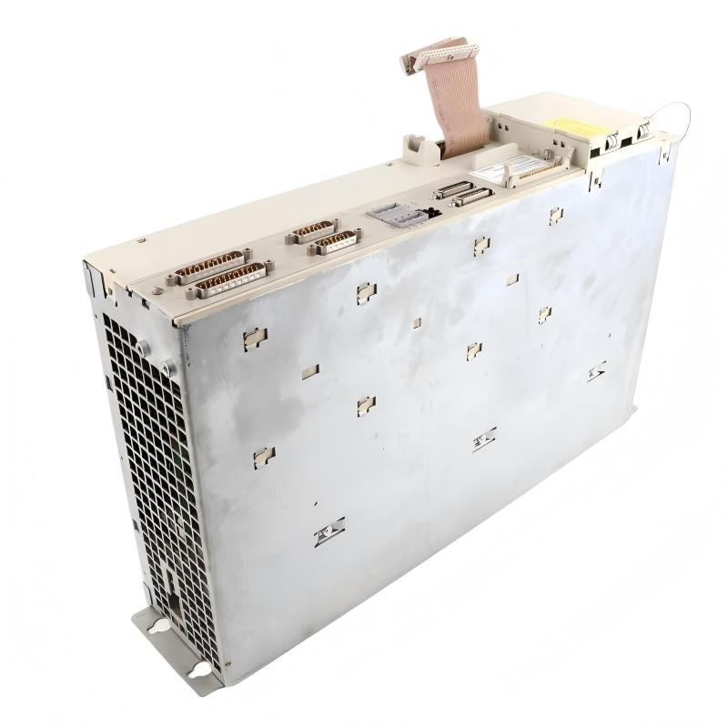
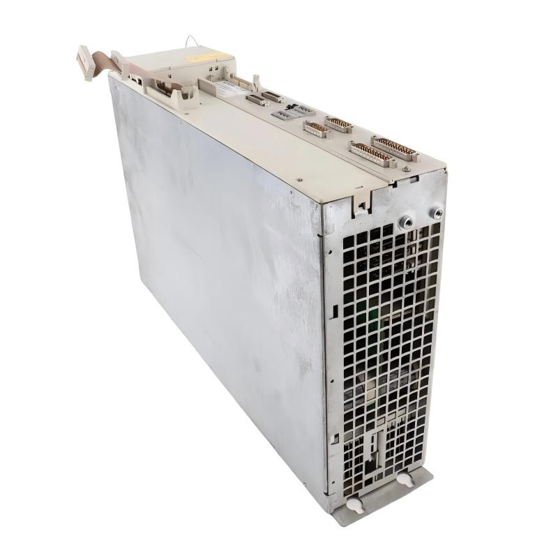
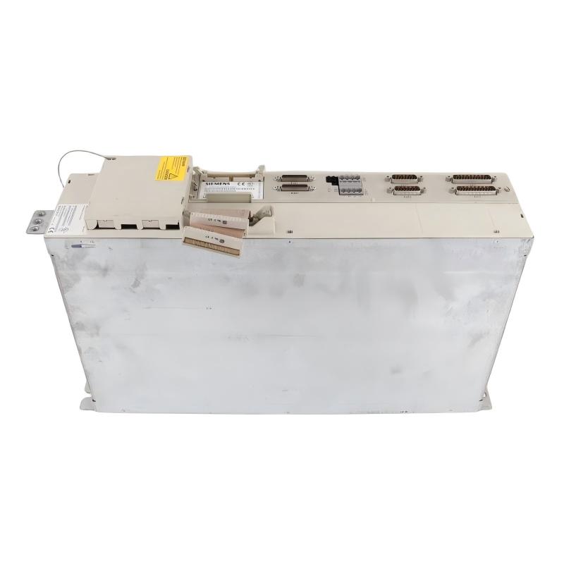
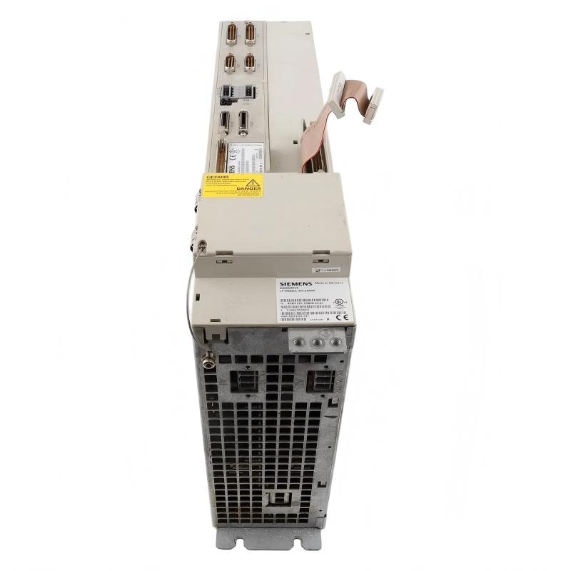
- Siemens
- 6SN1123-1AB00-0CA1
- Power Module
- Germany
- 483 × 102 × 254 mm
- 10 kg
- Xiamen, China
- New & In Stock
- T/T, PayPal, Western Union
- 1 Year
- 1-3 Working Days
- DHL, UPS, TNT, FedEx and EMS.
- 24-Hour Service
- COO
- 3
Our advantage

Global Logistics
We have a 10-year logistics and express cooperation agreement, so our products can be shipped to any place in the world.

Brand new and original
Our products are imported in bulk from the place of origin. Because of the cooperative relationship, our products are all original and 100% new.

24-hour service
We provide 7*24 hours service to our customers. We will be there whenever you need us.

Price advantage
All our products are priced very favorably because we have our own warehouse and supply.
| Company Information | |||
| [email protected] | |||
| Mobile | +8615980777398 | ||
| +8615980777398 | |||
| 15980777398 |
1. Product Overview
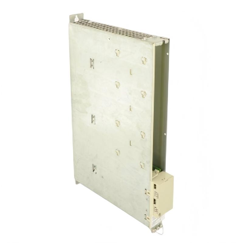
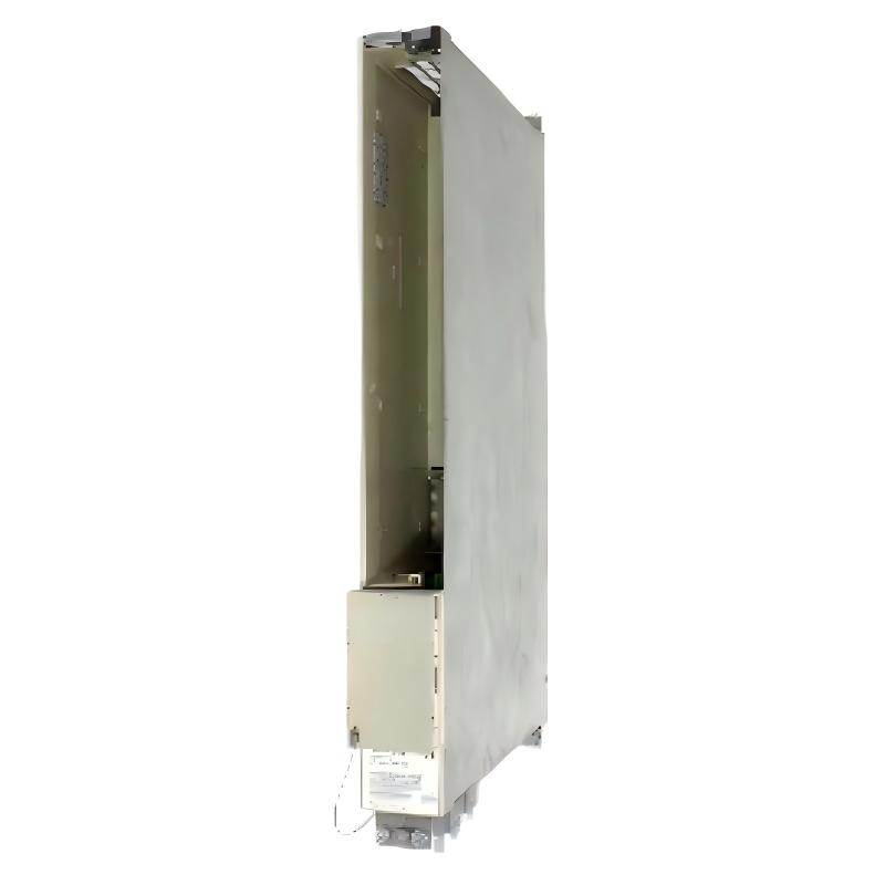
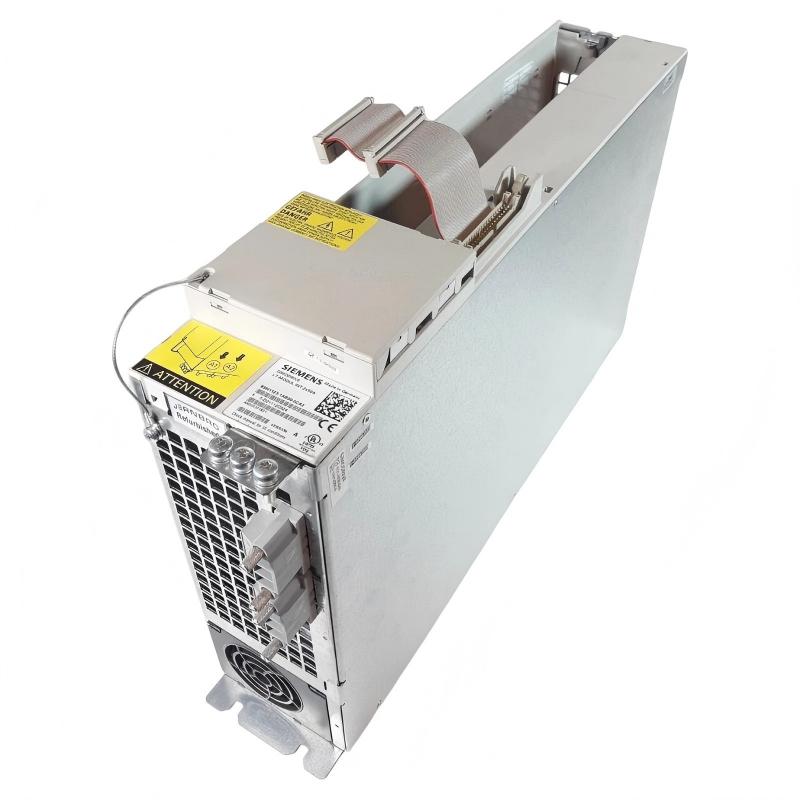
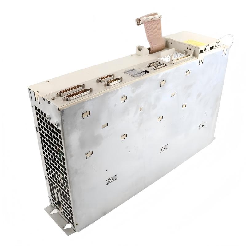
The Siemens 6SN1123-1AB00-0CA1 Power Module is an industrial drive-system component associated with Siemens SIMODRIVE automation technology. Power modules in servo-drive systems provide the power conversion and control interface required to operate compatible motors and support precise motion-control applications.
In industrial automation, drive power components work alongside controllers, motor feedback devices, power supplies, and communication or interface components. Their role is to support controlled motor operation in applications where speed, torque, and positioning must be coordinated with the wider machine-control system.
The Siemens 6SN1123-1AB00-0CA1 is intended for use in a compatible drive configuration. Correct selection depends on the complete drive architecture, including the associated power supply, motor ratings, control components, and system version. The full order number must be checked carefully because modules with similar Siemens part numbers may differ in electrical ratings, supported configurations, and application requirements.
The supplied dimensions are 483 × 102 × 254 mm, and the stated weight is 10 kg. These specifications are useful for planning cabinet space, mounting arrangements, handling procedures, and replacement work.
Before installation or replacement, engineers should verify the exact electrical ratings, supported motor configuration, cooling requirements, connector assignments, and compatibility with the installed Siemens drive system.
2. Technical Specifications
| Parameter | Specification |
|---|---|
| Brand | Siemens |
| Model | 6SN1123-1AB00-0CA1 |
| Product Type | Power Module |
| Product Family | SIMODRIVE-related drive technology; verify the exact system designation |
| Product Category | Industrial drive and motion control |
| Primary Function | Drive power conversion and motor operation within a compatible configuration |
| Dimensions | 483 × 102 × 254 mm |
| Weight | 10 kg |
| Supported Motor Types | Confirm from the applicable technical documentation |
| Rated Output | Verify the exact module rating |
| Input and DC-Link Requirements | Confirm from the approved drive configuration |
| Cooling Requirements | Verify the specified cooling method and airflow requirements |
| Drive-System Compatibility | Confirm the complete system configuration and hardware revision |
| Installation Environment | Industrial control cabinet, subject to product ratings |
The dimensions and weight are based on the supplied product information. Electrical ratings, output characteristics, and other unprovided specifications must be confirmed from the documentation for the exact module before installation or commissioning.
3. Function and Working Principle
A drive power module is part of the electrical system that enables a compatible motor to operate under controlled conditions. In a servo-drive architecture, power conversion and control functions work together to produce the motor response required by the application.
3.1 Power Conversion
Industrial drive systems receive electrical power from a designated supply arrangement. The drive’s power components process that energy to support the operation of the connected motor.
The precise power-conversion arrangement, voltage requirements, and output characteristics of the 6SN1123-1AB00-0CA1 must be verified against the exact technical documentation and system configuration.
3.2 Motor Operation
In a compatible motion-control system, the drive works with control electronics to regulate motor behavior. Depending on the system design, this may involve speed control, torque regulation, or positioning functions.
The module must be matched to the motor and associated drive components. Incorrect combinations can cause drive faults, unstable operation, or equipment damage.
3.3 Coordination with the Control System
A drive system typically receives commands from a motion controller or automation controller. The controller determines the required machine movement, while the drive system executes the commands within its supported operating limits.
The complete configuration may include power components, control electronics, feedback devices, motor cables, and system interfaces. The precise components required for this model should be confirmed before integration.
3.4 Fault Monitoring and Protection
Industrial drive systems may provide diagnostics for conditions such as overcurrent, overtemperature, DC-link problems, communication faults, or motor-related issues. The available protection functions depend on the installed hardware and system configuration.
When a fault occurs, maintenance personnel should review the actual diagnostic code and follow the applicable troubleshooting procedure instead of assuming that the power module itself is defective.
4. Role in Industrial Automation Systems
Power modules are important in motion-control applications because they enable controlled motor operation within automated production equipment.
Servo Motion Control
Compatible drive systems can support precise motor movements for machinery requiring repeatable positioning and controlled acceleration or deceleration. The actual performance depends on the complete drive and motor configuration.
Production Machinery
Automated production equipment may use servo drives to move machine axes, position workpieces, and coordinate mechanical processes. A correctly matched power module contributes to the operation of the overall drive system.
Packaging and Material Handling
Packaging machines and material-handling equipment often require coordinated motor movement. Drive components help execute the motion commands generated by the control system.
Machine Tool Applications
Motion-control systems are used in machine tools and other equipment where controlled movement is essential. Compatibility with the specific machine architecture and motor configuration must be established before selecting a replacement module.
System Maintenance and Replacement
Industrial drive components may remain in service for many years. When a module requires replacement, engineers should compare the complete order number, hardware configuration, electrical ratings, and associated components to avoid introducing compatibility problems.
5. Industrial Applications
Manufacturing Equipment
Servo-drive systems are used in automated manufacturing lines for controlled movement, repeatable positioning, and coordination between machine stations. A compatible power module supports the drive architecture used in these applications.
Packaging Machinery
Packaging equipment may require synchronized movements for feeding, cutting, sealing, labeling, and product handling. The drive system must be correctly matched to the motor and the machine’s motion requirements.
Material Handling Systems
Automated handling equipment can use controlled motor drives for positioning, transfer, and movement of mechanical assemblies. Correct drive configuration supports predictable machine operation.
Machine Tools
Machine tools may rely on servo-drive technology for axis movement and other controlled mechanical functions. The selected module must be compatible with the installed drive platform and the relevant motor specifications.
Industrial Retrofit Projects
During equipment refurbishment, a power module may need to be replaced while preserving the existing control architecture. Engineers should verify the exact part number, system compatibility, and commissioning requirements before installing a replacement.
6. Installation and System Integration
Correct installation is essential for electrical safety, reliable operation, and long-term drive performance.
6.1 Verify the Complete Order Number
Confirm that the module label reads Siemens 6SN1123-1AB00-0CA1. Compare the order number and hardware revision with the installed system documentation.
Do not assume that a visually similar Siemens drive module is interchangeable. Variations in electrical ratings, interfaces, and drive configurations can affect compatibility.
6.2 Check Mechanical Installation
The supplied dimensions are 483 × 102 × 254 mm, and the stated weight is 10 kg. Verify that the cabinet provides adequate space for mounting, cable routing, ventilation, and maintenance access.
Because the module weighs 10 kg, use suitable handling equipment and follow the applicable lifting and mounting procedures. Confirm the required mounting orientation and mechanical support from the product documentation.
6.3 Isolate Electrical Power
Before installation or replacement, follow the approved lockout and isolation procedure. Disconnect the relevant power sources and verify that the equipment is in a safe state.
Drive systems may contain capacitors that retain hazardous electrical energy after the supply has been disconnected. Follow the specified discharge waiting time and verify the safe electrical condition using an appropriate method before handling power connections.
6.4 Verify Electrical Connections
Check all power, motor, control, and grounding connections against the correct wiring diagrams. Confirm conductor sizes, terminal assignments, tightening requirements, and the specified electrical ratings.
Never connect the module based solely on connector appearance or the specifications of a different model.
6.5 Confirm Drive-System Compatibility
Verify the associated power supply, control components, motor, feedback system, firmware where applicable, and system configuration. Ensure that the complete combination is approved for the intended installation.
If the module is being installed as a replacement, compare the original and replacement order numbers and review any required configuration changes.
6.6 Perform Commissioning Checks
After installation, inspect the wiring and mechanical mounting before applying power. Follow the system’s approved startup procedure and review any diagnostic messages.
Verify that the drive recognizes the installed components and that the motor operates within the specified limits. Test the equipment under controlled conditions before returning it to normal production service.
7. Troubleshooting Common Problems
Problem 1: The Drive System Does Not Start
Possible causes:
- Missing or incorrect power supply.
- Incorrect control configuration.
- An active drive fault.
- A disconnected interface or control connection.
- An incompatible module or system combination.
Recommended checks:
- Record the displayed fault code or diagnostic message.
- Verify the power supply and system status according to the approved procedure.
- Check control and interface connections.
- Confirm that the installed module matches the system configuration.
- Resolve the underlying fault before attempting another startup.
Problem 2: Overcurrent or Drive Protection Fault
Possible causes:
- Motor cable short circuit or insulation damage.
- Incorrect motor data or configuration.
- Mechanical obstruction or excessive load.
- Motor or drive component failure.
- Incorrect wiring.
Recommended checks:
Follow the drive’s fault-specific troubleshooting procedure. Inspect the motor cable and connected equipment using approved methods, and compare motor data with the system configuration. Do not repeatedly reset an overcurrent fault without identifying the cause.
Problem 3: Overtemperature or Thermal Warning
Possible causes:
- Restricted airflow.
- Blocked ventilation openings.
- Excessive ambient temperature.
- Overload or unsuitable operating conditions.
- Cooling-system malfunction.
Recommended checks:
Check cabinet temperature, ventilation paths, and the specified cooling arrangement. Verify that the module is operating within its permitted environmental and load limits. Allow the equipment to cool according to the approved procedure before further testing.
Problem 4: Unstable Motor Operation
Possible causes:
- Incorrect drive or motor configuration.
- Feedback wiring problems.
- Mechanical binding.
- Incorrect control parameters.
- Power or connection problems.
Recommended checks:
Review the drive diagnostics and compare the configured motor data with the installed motor. Inspect feedback and motor connections, and check for mechanical restrictions using safe maintenance procedures.
Problem 5: The Replacement Module Is Not Recognized
Possible causes:
- Incorrect order number.
- Incompatible hardware version.
- Incorrect system configuration.
- Missing or improperly connected interfaces.
- A fault in another system component.
Recommended checks:
Compare the replacement module with the original hardware documentation. Verify system compatibility and all relevant connections. Complete the required configuration and commissioning procedure before returning the drive to operation.
8. Compatible System Components
A power module must operate as part of a compatible drive configuration. The following component categories may be relevant, depending on the exact system design.
| Component Category | Function | Verification Required |
|---|---|---|
| Compatible drive power supply | Supplies power to the drive system | Voltage, current capacity, and system compatibility |
| Drive control unit or control electronics | Processes motion commands and regulates drive operation | Exact supported configuration |
| Compatible servo motor | Converts electrical power into controlled mechanical movement | Motor ratings and drive compatibility |
| Motor power cables | Connect the drive to the motor | Current rating, cable type, and connector arrangement |
| Feedback device and cable | Provides motor position or speed information where required | Supported feedback type and interface |
| Cooling components | Maintain suitable operating temperature | Required cooling method and airflow |
| Protective devices and grounding components | Support electrical protection and safe installation | Applicable electrical design requirements |
This table describes general component categories, not a guaranteed compatibility list for the exact part number. Verify the approved combination before purchasing or installing components.
9. Replacement and Alternative Selection
Selecting a replacement for the Siemens 6SN1123-1AB00-0CA1 requires checking the complete electrical and mechanical configuration.
| Selection Factor | What to Verify |
|---|---|
| Exact order number | Confirm 6SN1123-1AB00-0CA1 |
| Electrical ratings | Match the specified supply and output requirements |
| Motor compatibility | Confirm the connected motor is supported |
| Drive architecture | Verify compatibility with the existing power supply and control electronics |
| Feedback and interfaces | Check the supported feedback and control connections |
| Cooling requirements | Match the specified cooling arrangement |
| Mechanical dimensions | Compare against 483 × 102 × 254 mm |
| Weight and handling | Account for the stated 10 kg weight |
| Configuration | Determine whether system settings or hardware changes are required |
| Commissioning | Perform required startup and functional checks |
A module should not be treated as a direct replacement solely because it belongs to the same Siemens product family or has a similar appearance. Confirm compatibility with the complete drive system before installation.
10. Key Advantages
When correctly selected and integrated, a compatible drive power module can provide several practical benefits:
- Industrial motion-control integration: Supports motor operation within a compatible drive architecture.
- Compact cabinet planning: The supplied dimensions help engineers plan installation space and access.
- Structured drive configuration: Works with the appropriate control and power components to support automated machine movement.
- Maintenance and replacement planning: The full order number helps identify the intended hardware during service work.
- System-level diagnostics: Available drive diagnostics can assist technicians in identifying faults and narrowing down possible causes.
- Broad application relevance: Compatible drive systems may be used in manufacturing, packaging, material handling, and machine-tool applications.
Actual performance depends on the verified module specifications, associated equipment, installation conditions, and drive configuration.
11. Technical FAQs
What is the Siemens 6SN1123-1AB00-0CA1?
It is identified as a Siemens Power Module associated with industrial drive technology. The exact drive-system designation, electrical ratings, and supported configuration should be verified from the product documentation.
What are the dimensions and weight?
The supplied dimensions are 483 × 102 × 254 mm, and the stated weight is 10 kg.
What should be checked before installing the module?
Confirm the exact order number, electrical ratings, motor compatibility, drive architecture, cooling requirements, grounding, and connection assignments. Follow the approved electrical isolation and installation procedures.
Can the module replace another Siemens power module?
Not automatically. Compatibility depends on the complete order number, electrical ratings, drive configuration, motor requirements, and hardware version. Verify the approved replacement details before installation.
Why might the drive report an overcurrent fault?
Possible causes include motor-cable problems, incorrect configuration, excessive mechanical load, wiring faults, or a defective component. Use the actual diagnostic code and approved troubleshooting procedure to determine the cause.
Why is cooling important?
Drive power components generate heat during operation. Restricted airflow, unsuitable ambient temperatures, or cooling-system problems can cause thermal warnings or shutdowns. Follow the cooling and environmental requirements for the exact module.
What precautions are necessary during replacement?
Isolate the power supply, follow lockout procedures, and observe the specified discharge time for stored electrical energy. Verify the safe condition of the equipment before handling connections, and use appropriate handling equipment for the 10 kg module.
12. Conclusion
The Siemens 6SN1123-1AB00-0CA1 Power Module is an industrial drive-system component intended for use in a compatible motor-control configuration. Its supplied dimensions of 483 × 102 × 254 mm and weight of 10 kg are important considerations for cabinet design, installation, and replacement planning.
Reliable operation depends on matching the module to the correct power supply, control components, motor, feedback system, and cooling arrangement. Engineers should verify the exact electrical specifications and approved system configuration before installation or commissioning.
For maintenance teams and system integrators, confirming the complete order number, following electrical safety procedures, and completing the required commissioning checks are essential steps when installing or replacing the Siemens 6SN1123-1AB00-0CA1.