

ProductPRODUCT
Featured products



Contact Us
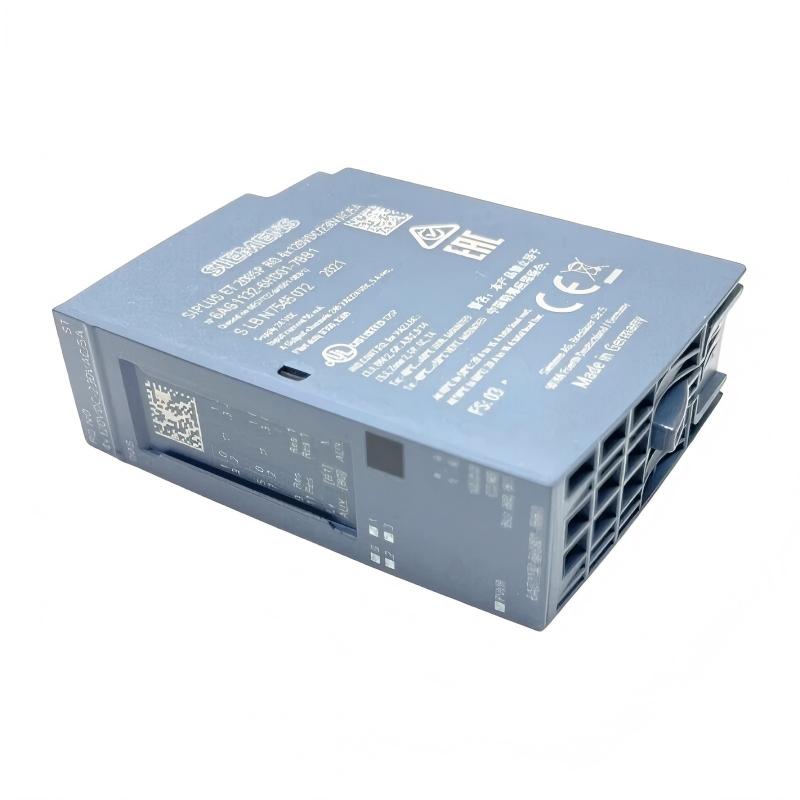
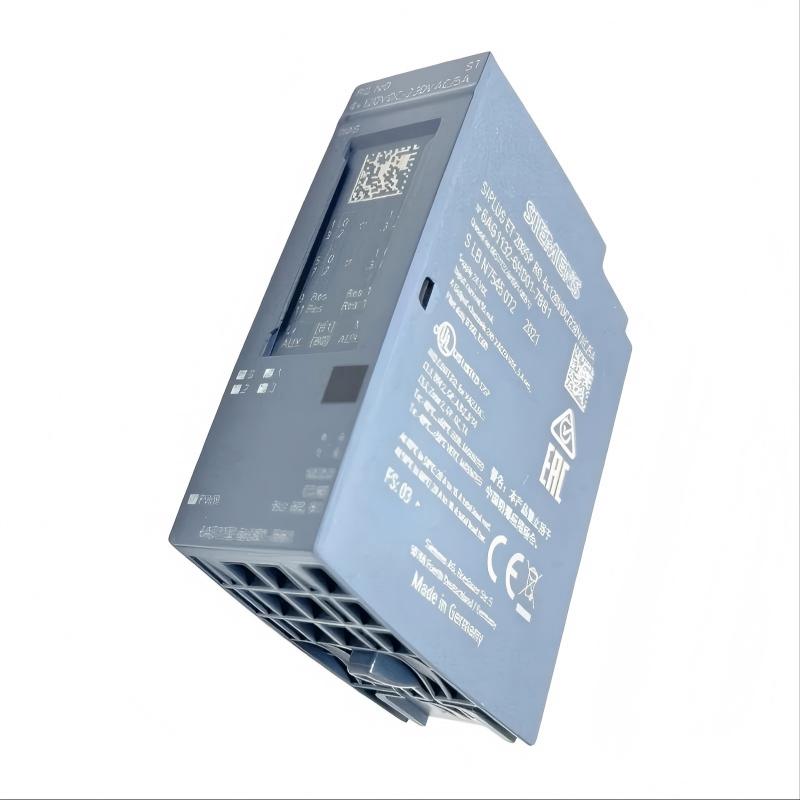
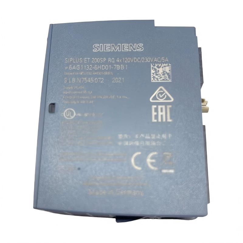
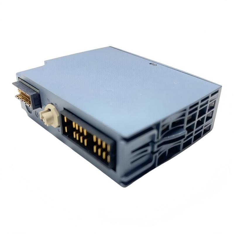
- Siemens
- 6AG1132-6HD01-7BB1
- Digital Output Module
- Germany
- 20 × 73 × 58 mm
- 0.04 kg
- Xiamen, China
- New & In Stock
- T/T, PayPal, Western Union
- 1 Year
- 1-3 Working Days
- DHL, UPS, TNT, FedEx and EMS.
- 24-Hour Service
- COO
- 69
Our advantage

Global Logistics
We have a 10-year logistics and express cooperation agreement, so our products can be shipped to any place in the world.

Brand new and original
Our products are imported in bulk from the place of origin. Because of the cooperative relationship, our products are all original and 100% new.

24-hour service
We provide 7*24 hours service to our customers. We will be there whenever you need us.

Price advantage
All our products are priced very favorably because we have our own warehouse and supply.
| Company Information | |||
| [email protected] | |||
| Mobile | +8615980777398 | ||
| +8615980777398 | |||
| 15980777398 |
Product Overview
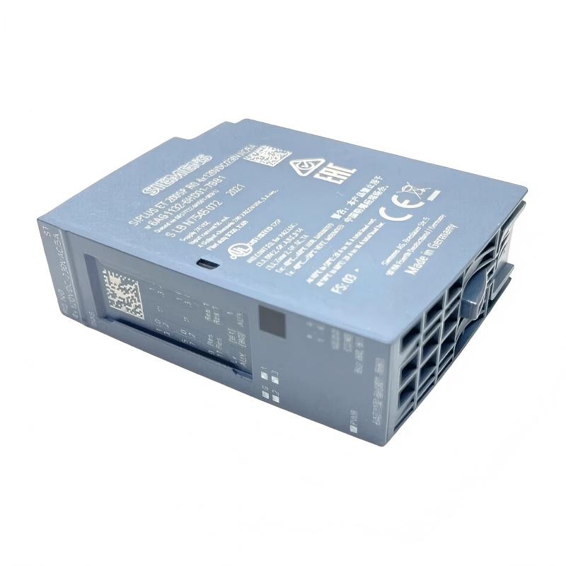
The Siemens 6AG1132-6HD01-7BB1 is a SIPLUS ET 200SP digital output module designed for industrial automation systems requiring relay-based switching and enhanced environmental resistance. It provides four relay outputs and is based on the ET 200SP RQ output architecture.
The module uses normally open relay contacts and is intended for switching circuits in the applicable AC and DC voltage ranges. Its SIPLUS design incorporates conformal coating and an extended temperature capability, making it appropriate for demanding industrial environments.
The supplied product information is:
- Manufacturer: Siemens
- Product Family: SIPLUS ET 200SP
- Model: 6AG1132-6HD01-7BB1
- Product Type: Digital Output Module
- Output Type: Relay
- Number of Outputs: 4
- Relay Contact: Normally Open
- Dimensions: 20 × 73 × 58 mm
- Weight: 0.04 kg
- Application: Industrial Automation
For system design, the module should be selected together with the appropriate ET 200SP BaseUnit and external load protection. The exact wiring and load arrangement should follow the approved machine electrical design.
Technical Specifications
| Parameter | Specification |
|---|---|
| Manufacturer | Siemens |
| Product Family | SIPLUS ET 200SP |
| Model | 6AG1132-6HD01-7BB1 |
| Product Type | Digital Output Module |
| Output Technology | Relay |
| Number of Outputs | 4 |
| Contact Type | Normally Open |
| Rated Control Supply | 24 V DC |
| Output Voltage Range | 24 V DC to 120 V DC / 24 V AC to 230 V AC |
| Maximum Current per Channel | 5 A |
| Maximum Current per Module | 20 A |
| Output Switching Frequency | Up to 2 Hz resistive load; lower for inductive loads |
| Module Diagnostics | Yes |
| Conformal Coating | Yes |
| Temperature Capability | Approximately -40 °C to +70 °C |
| Suitable BaseUnit | B0 or B1 |
| Dimensions | 20 × 73 × 58 mm |
| Weight | 0.04 kg |
| System | ET 200SP |
| Application | Industrial Automation |
The module is identified as an ET 200SP SIPLUS relay output module with four 120 V DC to 230 V AC / 5 A normally-open relay outputs, conformal coating, extended temperature capability, and module diagnostics.
Function and Working Principle
The 6AG1132-6HD01-7BB1 converts PLC output commands into physical switching actions through four internal relay channels.
A typical signal path is:
PLC CPU
↓
ET 200SP Interface
↓
6AG1132-6HD01-7BB1
↓
Relay Contact
↓
External Power Circuit
↓
Field Load
When the PLC program activates an output channel, the corresponding relay changes state and completes the external load circuit.
Typical loads include:
- Contactors
- Solenoid valves
- Auxiliary relays
- Industrial actuators
- Motor control circuits
- Heating control circuits
- Signal lamps
- Auxiliary machinery
The relay architecture provides electrical separation between the electronic control system and the switched load circuits.
Role in Industrial Control Systems
The digital output module is the interface between PLC logic and physical equipment.
The 6AG1132-6HD01-7BB1 can perform functions such as:
- Switching external AC circuits
- Switching external DC circuits
- Controlling contactors
- Operating solenoid valves
- Controlling auxiliary relays
- Activating machine actuators
- Providing status or alarm outputs
The four independent relay channels allow multiple field devices to be controlled from a single compact ET 200SP station.
Typical Industrial Applications
Manufacturing Automation
The module can be used in:
- Assembly lines
- Production machinery
- Automated inspection systems
- Conveyor systems
- Machine tools
- Material handling equipment
Relay outputs are especially useful when PLC control logic needs to switch external devices with different voltage requirements.
Packaging Equipment
Potential applications include:
- Filling machines
- Labeling machines
- Wrapping systems
- Cartoning equipment
- Sorting machinery
- Palletizing systems
The output channels can control auxiliary actuators and switching components as part of an automated sequence.
Process Automation
Typical applications include:
- Pump control
- Valve control
- Heating systems
- Water treatment
- Utility automation
- Process equipment
The relay output architecture provides flexibility for industrial switching circuits.
Installation Guide
1. Verify Product Identification
Before installation, confirm:
Siemens 6AG1132-6HD01-7BB1
Inspect the module for:
- Cracked housing
- Bent contacts
- Damaged connectors
- Corrosion
- Contamination
- Burn marks
- Mechanical damage
Do not install a damaged module.
2. Verify the BaseUnit
The module is intended for the appropriate ET 200SP BaseUnit configuration. The specified compatible BaseUnit types are B0 and B1.
Before installation:
- Confirm the BaseUnit type.
- Inspect the mechanical interface.
- Check the BaseUnit mounting.
- Ensure the electrical interface is clean.
3. Isolate Power
Before installation or replacement:
- Shut down the machine.
- Disconnect applicable electrical supplies.
- Apply the required lockout/tagout procedure.
- Verify absence of hazardous voltage.
- Ensure connected loads cannot start unexpectedly.
Because relay outputs may switch high-energy circuits, electrical isolation is particularly important.
4. Install the Module
Insert the module into the designated ET 200SP BaseUnit.
Verify:
- Correct orientation
- Complete mechanical engagement
- Secure locking
- Proper BaseUnit connection
- Adequate cabinet clearance
Do not force the module into place.
5. Connect Output Circuits
Wire the four relay outputs according to the electrical drawings.
Before energizing the system, verify:
- Channel assignment
- Load voltage
- Load current
- Wire size
- Protective devices
- Terminal arrangement
- External power source
- Load polarity where applicable
6. Check Load Characteristics
The output rating must be evaluated according to the actual load.
Different loads impose different electrical stresses:
- Resistive loads
- Inductive loads
- Lamp loads
- Contactors
- Solenoid valves
- Motors
Inductive loads can generate switching transients and may require appropriate suppression.
Commissioning Procedure
Step 1 — Mechanical Inspection
Verify that the module and BaseUnit are securely installed.
Step 2 — Wiring Verification
Compare each output connection with the approved electrical drawings.
Step 3 — Load Verification
Confirm the voltage and current of each connected load.
Step 4 — Power-Up
Restore system power according to the commissioning procedure.
Step 5 — Diagnostic Inspection
Check module diagnostic status.
Step 6 — Individual Output Test
Activate each output channel separately.
Step 7 — Field Load Test
Verify that every connected device responds correctly.
Step 8 — PLC Sequence Test
Run the automation program through representative operating sequences.
Step 9 — Protection Verification
Check that external fuses, circuit breakers, and protective devices operate correctly.
Step 10 — Final Inspection
Verify wiring, labeling, terminal security, and cabinet condition.
Troubleshooting Guide
Problem 1: Output Does Not Activate
Possible causes include:
- PLC program does not command the output
- Incorrect output address
- Module communication problem
- Wiring error
- External power failure
- Load failure
- Relay output fault
Recommended Procedure
Check the fault from the PLC outward:
- Verify PLC output command.
- Check module diagnostic status.
- Verify BaseUnit connection.
- Check output wiring.
- Measure external supply voltage.
- Check the field load.
Problem 2: PLC Shows Output ON but Load Remains OFF
Possible causes:
- Broken field wiring
- Open fuse
- Incorrect terminal connection
- Failed load
- External power supply problem
- Relay contact problem
Trace the complete load circuit.
Problem 3: Output Remains Energized
Possible causes:
- PLC program continuously commands ON
- Wiring bypass
- Relay contact problem
- External circuit fault
First determine whether the PLC output command is actually OFF.
If the command is OFF but the load remains energized, inspect the external circuit and relay contacts.
Problem 4: Output Is Intermittent
Possible causes:
- Loose connection
- Mechanical vibration
- Relay contact degradation
- Unstable supply
- Excessive electrical load
- Electrical interference
Monitor both the PLC command and field circuit voltage while the fault occurs.
Problem 5: Several Outputs Fail Simultaneously
If multiple channels stop operating at the same time, check common system components before replacing individual field devices.
Possible causes include:
- Module power problem
- BaseUnit connection problem
- ET 200SP communication fault
- System configuration problem
- Common external power failure
- Module-level fault
Problem 6: Relay Output Becomes Hot
Possible causes include:
- Excessive current
- Incorrect load type
- Loose connection
- Repeated switching
- Overloaded circuit
- Poor terminal contact
Disconnect the affected circuit safely and investigate the cause of abnormal heating.
Problem 7: Inductive Load Causes Output Problems
Inductive loads such as contactors and solenoid valves can generate voltage transients during switching.
Possible symptoms include:
- Premature contact wear
- Electrical noise
- Intermittent operation
- Controller disturbances
Use suitable suppression and protection methods based on the load characteristics and electrical design.
Problem 8: Diagnostic Fault Appears
Possible causes include:
- Module configuration problem
- BaseUnit connection issue
- System communication fault
- Supply problem
- Hardware failure
Check the ET 200SP diagnostic information first, then inspect the physical installation.
Output Fault Diagnosis
A systematic troubleshooting path is recommended:
PLC Program
↓
Output Command
↓
ET 200SP Communication
↓
6AG1132-6HD01-7BB1
↓
Relay Channel
↓
Field Wiring
↓
External Power
↓
Load
This approach helps determine whether the fault is caused by software, communication, module hardware, wiring, power, or the field device.
Preventive Maintenance
| Inspection Item | Recommended Check |
|---|---|
| Module Housing | Inspect for damage |
| BaseUnit | Verify secure engagement |
| Output Wiring | Check terminal condition |
| Load Current | Confirm operating current |
| Relay Contacts | Check for abnormal heating |
| Cabinet Temperature | Monitor environmental conditions |
| Diagnostic Status | Review PLC diagnostics |
| External Power | Verify voltage stability |
| Protective Devices | Inspect periodically |
| Field Loads | Confirm normal operation |
Preventive maintenance is especially important in applications involving frequent relay switching or inductive loads.
Common Installation Mistakes
Exceeding the Output Rating
The maximum specified current is 5 A per channel. The total module output current is specified at 20 A, subject to installation and temperature conditions.
Operating relay contacts beyond their applicable rating can shorten service life and cause overheating.
Ignoring Load Type
A resistive heater and an inductive solenoid do not impose the same electrical stress on relay contacts.
Switching frequency and load characteristics must therefore be considered during system design.
Using the Wrong BaseUnit
The module is specified for B0 or B1 BaseUnits. Incorrect mechanical or electrical pairing can prevent proper operation.
Poor Output Identification
Incorrect labeling can cause a PLC command to operate the wrong field device.
Every output should be clearly identified during installation and commissioning.
Failing to Consider Temperature
The module’s total current capability can depend on installation orientation and ambient temperature. Thermal conditions should therefore be considered when several outputs operate simultaneously.
6AG1132-6HD01-7BB1 Troubleshooting Table
| Symptom | Possible Cause | Recommended Action |
|---|---|---|
| Output does not activate | No PLC command | Check PLC program |
| PLC shows ON but load is OFF | Field circuit problem | Check wiring and external power |
| Output remains ON | Relay or wiring fault | Check command and output circuit |
| Intermittent output | Loose connection | Inspect wiring and terminals |
| Several outputs fail | Module/system problem | Check diagnostics and BaseUnit |
| Relay becomes hot | Excessive load | Verify current and load type |
| Inductive load causes disturbances | Switching transient | Check suppression |
| Diagnostic alarm | Configuration or hardware fault | Check ET 200SP diagnostics |
Key Advantages
- Siemens SIPLUS ET 200SP architecture
- Four independent relay outputs
- Normally open relay contacts
- Suitable for AC and DC switching applications
- Up to 5 A per output
- Up to 20 A total module output current under applicable conditions
- Conformal-coated design
- Extended temperature capability
- Module diagnostics
- Electrical separation between channels and system circuits
- Compact 20 × 73 × 58 mm design
- Supplied weight of 0.04 kg
- Suitable for demanding industrial automation applications
Technical FAQs
What is the Siemens 6AG1132-6HD01-7BB1?
The Siemens 6AG1132-6HD01-7BB1 is a SIPLUS ET 200SP digital output module with four normally open relay outputs.
How many outputs does the module provide?
It provides four digital relay outputs.
What type of output does it use?
The module uses normally open relay contacts.
What is the maximum current per channel?
The specified maximum current is 5 A per channel, subject to the applicable load and environmental conditions.
What is the maximum total module current?
The specified maximum total output current is 20 A per module, with thermal limitations depending on installation conditions.
What are the dimensions?
The supplied dimensions are 20 × 73 × 58 mm.
What is the weight?
The supplied weight is 0.04 kg.
What BaseUnit is compatible with the module?
The specified BaseUnit types are B0 and B1.
What is the advantage of the SIPLUS version?
The SIPLUS version incorporates enhanced environmental characteristics, including conformal coating and an extended temperature range, making it suitable for more demanding industrial environments.
Why does the output not switch even though the PLC program is correct?
Check module diagnostics, BaseUnit connection, external power, output wiring, protective devices, and the field load. A correct PLC command does not necessarily mean that the external circuit is complete.
Why does a relay output become hot?
Excessive load current, unsuitable load characteristics, loose terminals, repeated switching, or poor electrical connections can cause abnormal heating.
Can the module switch inductive loads?
Relay outputs can be used for suitable inductive loads, but inductive switching generates electrical transients. Load characteristics, switching frequency, protection, and suppression should be considered during design.
What should I check if several output channels fail simultaneously?
Check the module diagnostic status, ET 200SP communication, BaseUnit connection, system power, and common field power before replacing individual devices.
Conclusion
The Siemens 6AG1132-6HD01-7BB1 Digital Output Module is a compact SIPLUS ET 200SP relay output module designed for industrial applications requiring reliable switching of external AC and DC circuits. Its four normally open relay outputs provide a flexible interface between PLC control logic and field equipment.
The module’s 20 × 73 × 58 mm dimensions and 0.04 kg supplied weight make it suitable for space-efficient ET 200SP control cabinets. Its conformal-coated construction and extended environmental capability make it appropriate for applications where standard automation hardware may face more demanding operating conditions.
For reliable operation, technicians should pay particular attention to BaseUnit selection, output load ratings, wiring quality, external circuit protection, inductive-load suppression, and thermal conditions. During troubleshooting, following the complete path from PLC command to relay output, field wiring, external power, and final load provides a structured way to identify faults and avoid unnecessary component replacement.