

ProductPRODUCT
Featured products




Contact Us
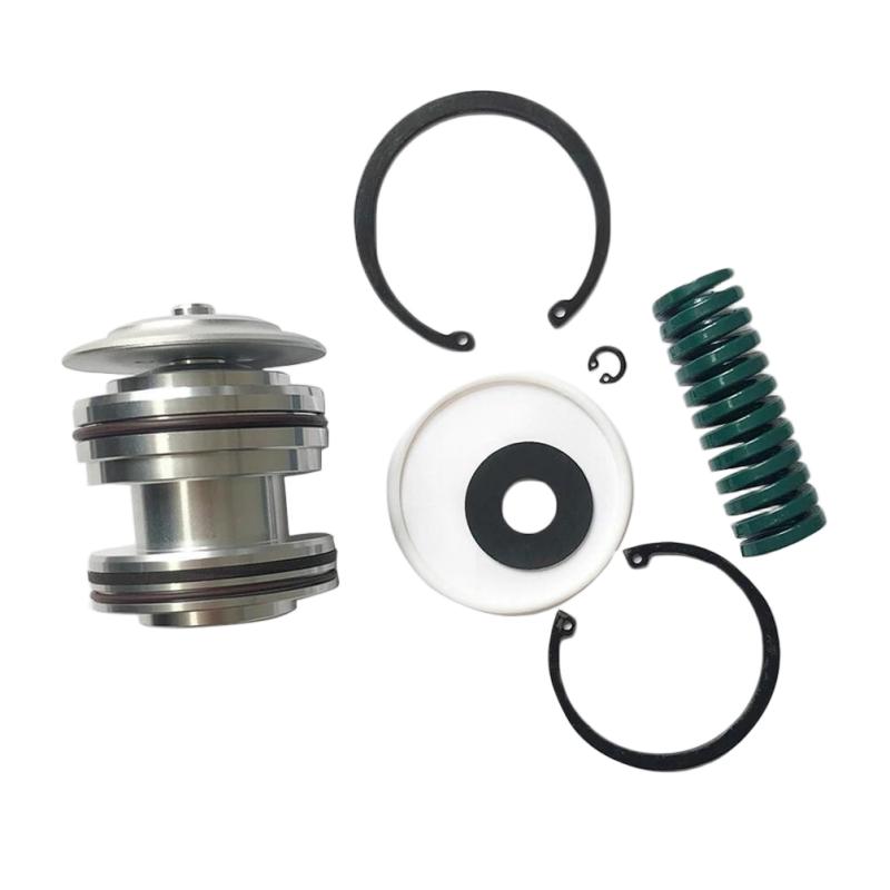
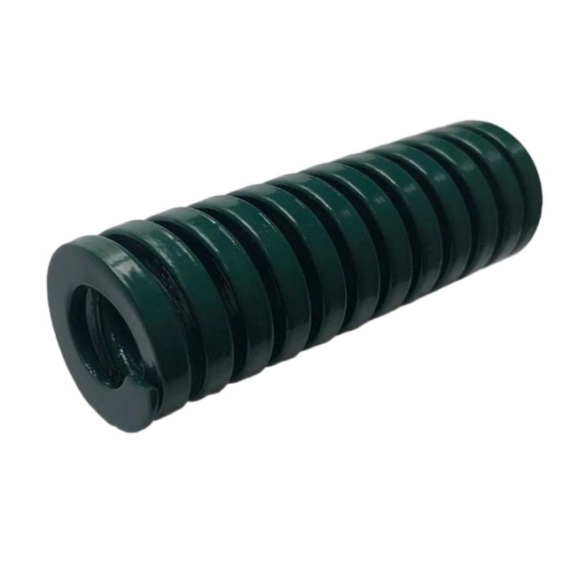
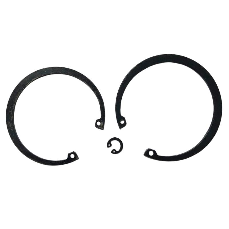
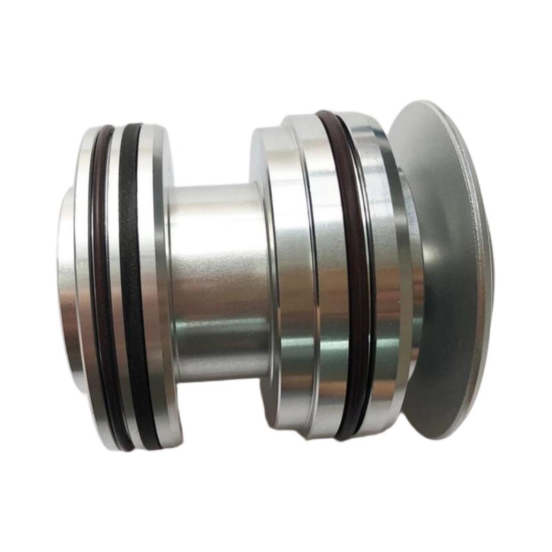
- Ingersoll Rand
- 47704430001 47704440001
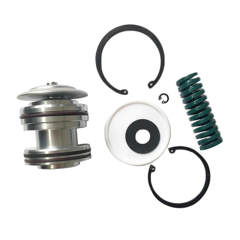
- Intake Valve Maintenance Kit
- USA
- 100 x 15 x 80 mm
- 0.4 kg
- Xiamen, China
- New & In Stock
- T/T, PayPal, Western Union
- 1 Year
- 1-3 Working Days
- DHL, UPS, TNT, FedEx and EMS.
- 24-Hour Service
- COO
- 73
Our advantage

Global Logistics
We have a 10-year logistics and express cooperation agreement, so our products can be shipped to any place in the world.

Brand new and original
Our products are imported in bulk from the place of origin. Because of the cooperative relationship, our products are all original and 100% new.

24-hour service
We provide 7*24 hours service to our customers. We will be there whenever you need us.

Price advantage
All our products are priced very favorably because we have our own warehouse and supply.
| Company Information | |||
| [email protected] | |||
| Mobile | +8615980777398 | ||
| +8615980777398 | |||
| 15980777398 |
Product Overview
The Ingersoll Rand 47704430001 47704440001 Intake Valve Maintenance Kit is a maintenance component intended for servicing compatible Ingersoll Rand industrial air compressor intake valve assemblies. The intake valve is an important part of the compressor air-handling system because it regulates the amount of air entering the compression stage according to the operating condition of the machine.
In a compressor, the intake valve may operate in conjunction with the compressor controller, pressure-control system, unload mechanism, and other pneumatic or mechanical components. Its condition can therefore have a direct influence on compressor loading, unloading, capacity control, starting behavior, and overall operating stability.
A maintenance kit is useful when the existing intake valve remains mechanically serviceable but its wear components, sealing elements, or other maintenance parts require replacement. Proper servicing can help restore valve movement and sealing performance without unnecessarily replacing the entire assembly.
The supplied product information is:
- Manufacturer: Ingersoll Rand
- Reference: 47704430001
- Part Number: 47704440001
- Product Type: Intake Valve Maintenance Kit
- Application: Industrial Air Compressor Maintenance
- Dimensions: 100 × 15 × 80 mm
- Weight: 0.4 kg
- Primary Function: Intake Valve Maintenance
- System Role: Compressor Air Intake and Capacity Control
Because the contents of a maintenance kit can depend on the associated compressor and valve configuration, technicians should confirm the applicable service arrangement before beginning disassembly.
Technical Specifications
| Parameter | Specification |
|---|---|
| Manufacturer | Ingersoll Rand |
| Reference | 47704430001 |
| Part Number | 47704440001 |
| Product Type | Intake Valve Maintenance Kit |
| Application | Industrial Air Compressor |
| Dimensions | 100 × 15 × 80 mm |
| Weight | 0.4 kg |
| System Function | Intake Air Regulation |
| Installation Location | Compressor Intake Valve Assembly |
| Maintenance Type | Valve Service / Overhaul |
| Primary Purpose | Restore Intake Valve Performance |
The supplied dimensions and weight are useful when planning maintenance inventory and preparing replacement components for compressor service.
Function and Working Principle
The intake valve controls the flow of atmospheric air into the compressor’s compression system.
A simplified operating path is:
Atmospheric Air
↓
Air Filter
↓
Intake Valve
↓
Compression Element
↓
Air/Oil Separation System
↓
Compressed Air Outlet
The intake valve changes its operating position according to compressor demand.
During a loaded condition, the valve permits sufficient air to enter the compression element to satisfy the required compressed-air demand.
During an unloaded or reduced-load condition, the valve restricts or controls intake airflow so that the compressor does not continue operating at full capacity unnecessarily.
The intake valve therefore contributes to:
- Capacity control
- Compressor loading
- Compressor unloading
- Starting behavior
- Pressure regulation
- Energy management
- Stable compressor operation
Role in Industrial Compressor Systems
A rotary screw compressor or similar industrial compressor does not always need to operate at maximum air intake.
When compressed-air demand changes, the control system can adjust the intake valve to alter the amount of air entering the compression element.
A simplified control sequence is:
Compressed-Air Demand Increases
↓
Controller Requests Load
↓
Intake Valve Opens
↓
More Air Enters Compressor
↓
Compressor Produces More Compressed Air
Conversely:
Compressed-Air Demand Decreases
↓
Controller Requests Unload
↓
Intake Valve Restricts Airflow
↓
Compressor Reduces Effective Compression Load
This makes the intake valve an important mechanical component within the compressor’s capacity-control system.
Typical Applications
The 47704440001 maintenance kit can be used for service activities involving compatible intake valve assemblies.
Typical maintenance situations include:
- Intake valve leakage
- Valve sticking
- Loading problems
- Unloading problems
- Slow compressor response
- Abnormal compressor starting
- Poor capacity regulation
- Worn seals
- Internal valve wear
- Preventive compressor overhaul
The exact compressor models and intake valve configurations compatible with the maintenance kit should be confirmed before installation.
Installation Guide
1. Verify the Maintenance Kit
Before starting work, confirm:
Ingersoll Rand 47704430001
47704440001 Intake Valve Maintenance Kit
Compare the replacement components with the installed intake valve.
Inspect:
- Part number
- Component quantity
- Seal dimensions
- Mechanical components
- Valve arrangement
- Existing valve configuration
Do not begin disassembly until the correct maintenance components have been identified.
2. Shut Down the Compressor
Stop the compressor using the normal shutdown sequence.
Then isolate the machine according to the site’s approved lockout/tagout procedure.
The compressor should be:
- Shut down
- Electrically isolated
- Depressurized
- Allowed to cool
- Protected against accidental restart
Never service an intake valve on a running or pressurized compressor.
3. Verify Zero Energy Condition
Before opening the intake system, confirm that stored energy has been safely released.
Check for:
- Residual air pressure
- Pneumatic control pressure
- Stored mechanical energy
- Electrical energy
- Hot surfaces
The compressor should be in a safe maintenance state before disassembly.
4. Prepare the Work Area
Use a clean work area and prepare:
- Appropriate hand tools
- Clean cloths
- Approved cleaning materials
- Replacement maintenance components
- Suitable containers
- Torque tools where required
Prevent dust, dirt, and foreign material from entering the compressor air or lubrication system.
5. Record the Existing Valve Arrangement
Before removing the intake valve, document its original configuration.
Record:
- Valve orientation
- Pneumatic connections
- Control tubing
- Mounting position
- Component orientation
- Hose routing
Photos can be useful during reassembly.
6. Disconnect the Valve
Disconnect the control lines and mechanical connections associated with the intake valve.
Protect open connections from:
- Dirt
- Dust
- Moisture
- Foreign objects
Do not pull or bend pneumatic tubing excessively.
7. Remove the Intake Valve
Remove the valve assembly carefully from the compressor.
Inspect the surrounding area for:
- Oil contamination
- Dirt
- Foreign particles
- Damaged fittings
- Cracked tubing
- Abnormal wear
The condition around the valve can provide useful clues about the original fault.
8. Disassemble the Valve
Disassemble the valve in a controlled sequence.
Pay particular attention to:
- Springs
- Valve elements
- Seals
- O-rings
- Retaining components
- Pistons or diaphragms where applicable
Some components may be under spring force. Handle them carefully.
9. Inspect the Existing Components
Inspect the valve body and reusable components for:
- Scratches
- Wear
- Corrosion
- Deformation
- Contamination
- Cracks
- Sticking
- Damaged sealing surfaces
A maintenance kit can replace serviceable wear components, but a severely damaged valve body may require complete replacement.
10. Clean the Valve
Clean reusable components using a suitable maintenance method.
Remove:
- Old lubricant residue
- Dirt
- Deposits
- Foreign material
- Old sealing material
Do not use cleaning methods that could damage precision surfaces or seals.
11. Install Maintenance Components
Install the replacement components from the 47704440001 Intake Valve Maintenance Kit.
Pay special attention to:
- Seal orientation
- O-ring placement
- Spring positioning
- Valve-element orientation
- Retaining components
Do not force components into position.
If a replacement component does not fit correctly, stop and verify the part identification and assembly arrangement.
12. Lubricate Seals Where Required
Where the service procedure requires lubrication, use only a lubricant compatible with the compressor system and sealing material.
Avoid excessive lubricant.
Too much lubricant can potentially interfere with valve movement or contaminate the pneumatic control system.
13. Reassemble the Intake Valve
Reassemble the valve carefully.
Verify:
- Moving components move freely
- Seals are seated correctly
- No seal is pinched
- Springs are correctly positioned
- Retaining components are secure
- No foreign material remains inside the assembly
If specified tightening values are available for the particular valve assembly, use those values.
14. Reinstall the Valve
Install the repaired intake valve into the original position.
Reconnect:
- Pneumatic control lines
- Mechanical connections
- Mounting hardware
- Associated fittings
Ensure that connections are secure but not excessively tightened.
Commissioning Procedure
After installation, perform a controlled commissioning process.
Step 1 — Visual Inspection
Check:
- Valve position
- Pneumatic connections
- Mounting hardware
- Tubing
- Fittings
Step 2 — Leak Inspection
Check the control circuit for air leakage.
A small pneumatic leak can prevent the valve from reaching the required position.
Step 3 — Start the Compressor
Start the compressor according to the normal operating procedure.
Observe the intake valve response during startup.
Step 4 — Verify Loading
When the compressor receives a load command, verify that the intake valve responds correctly.
The valve should move smoothly without abnormal noise or hesitation.
Step 5 — Verify Unloading
When the compressor unloads, verify that the valve changes position appropriately.
Incorrect unloading behavior can cause unnecessary compressor loading and abnormal pressure behavior.
Step 6 — Monitor Compressor Pressure
Observe system pressure and compressor response.
Check for:
- Slow pressure response
- Excessive pressure
- Unstable pressure
- Frequent cycling
Step 7 — Check for Abnormal Noise
Listen for:
- Air leakage
- Valve chatter
- Mechanical impact
- Unusual vibration
Troubleshooting Guide
Problem 1: Compressor Will Not Load
Possible causes:
- Intake valve stuck closed
- Control pressure problem
- Damaged pneumatic tubing
- Incorrect valve assembly
- Internal valve contamination
- Damaged seal
- Controller command problem
Recommended Checks
- Verify the load command.
- Check control pressure.
- Inspect pneumatic tubing.
- Observe valve movement.
- Check internal components.
- Verify assembly orientation.
Problem 2: Compressor Will Not Unload
Possible causes include:
- Intake valve stuck open
- Control circuit problem
- Damaged valve component
- Incorrect spring installation
- Pneumatic control fault
- Controller output problem
An intake valve that remains open when unloading is requested can cause the compressor to continue taking in more air than intended.
Problem 3: Slow Loading Response
Possible causes:
- Restricted control line
- Pneumatic leakage
- Sticking valve
- Contaminated valve
- Weak spring
- Incorrect maintenance assembly
Check the control circuit before replacing the entire valve.
Problem 4: Compressor Loads and Unloads Abnormally
Possible causes:
- Unstable pressure signal
- Intake valve sticking
- Control-system fault
- Incorrect valve response
- Pneumatic leakage
- Incorrect pressure settings
The problem should be investigated across both the mechanical and control sides.
Problem 5: Intake Valve Leaks
Possible causes:
- Damaged seal
- Incorrect O-ring installation
- Worn valve seat
- Damaged valve element
- Foreign material
- Incorrect assembly
Inspect the sealing surfaces and replacement components.
Problem 6: Valve Sticks
Possible causes:
- Contamination
- Corrosion
- Internal wear
- Damaged seal
- Incorrect lubrication
- Mechanical deformation
Disassemble and inspect the valve if movement is not smooth.
Problem 7: Compressor Pressure Is Too High
Potential causes include:
- Intake valve not responding correctly
- Valve remaining too open
- Unloading control problem
- Pressure-control problem
- Incorrect system configuration
Check both the intake valve and the overall compressor control system.
Problem 8: Compressor Pressure Is Too Low
Possible causes:
- Intake valve not fully opening
- Control pressure insufficient
- Valve sticking
- Air filter restriction
- Compressor capacity problem
- Air leakage elsewhere
Do not assume that a low-pressure condition is caused exclusively by the intake valve.
Intake Valve Fault Diagnosis
A systematic troubleshooting sequence is recommended:
Controller Command
↓
Pneumatic Control Signal
↓
Control Tubing
↓
Intake Valve
↓
Valve Position
↓
Compressor Air Intake
↓
Compression Element
↓
Compressed-Air Pressure
This sequence helps technicians determine whether the fault is electrical, pneumatic, mechanical, or process-related.
Preventive Maintenance
| Inspection Item | Recommended Check |
|---|---|
| Intake Valve | Check movement |
| Valve Seals | Inspect for wear |
| O-Rings | Inspect condition |
| Springs | Check for deformation |
| Control Tubing | Inspect for leaks |
| Pneumatic Connections | Check tightness |
| Valve Housing | Check contamination |
| Air Filter | Check restriction |
| Loading Function | Verify response |
| Unloading Function | Verify response |
| Compressor Pressure | Monitor stability |
| Valve Noise | Check for abnormal operation |
Common Maintenance Mistakes
Reusing Damaged Seals
Old seals can harden, deform, or lose elasticity.
Replacing the applicable service components is one of the main purposes of a maintenance kit.
Incorrect Component Orientation
Internal valve components may have a specific orientation.
Incorrect installation can result in:
- Valve sticking
- Poor sealing
- Incorrect loading
- Incorrect unloading
- Air leakage
Contaminating the Valve
Dust and foreign particles can interfere with moving components.
Always work in a clean environment.
Ignoring Pneumatic Leaks
A small control-air leak can prevent the valve from operating correctly.
Always inspect tubing and fittings during maintenance.
Excessive Tightening
Over-tightening fittings can damage threads and sealing surfaces.
Follow the applicable assembly requirements.
Post-Maintenance Inspection Checklist
- Correct 47704440001 maintenance kit confirmed
- Compressor safely isolated
- Residual pressure released
- Existing valve configuration recorded
- Valve removed correctly
- Internal components inspected
- Valve cleaned
- Replacement seals installed
- Internal components correctly positioned
- Valve reassembled
- Pneumatic lines reconnected
- Connections checked
- Pneumatic leakage checked
- Compressor started safely
- Loading operation verified
- Unloading operation verified
- Compressor pressure monitored
- Final inspection completed
Key Advantages
- Designed for intake valve maintenance
- Supports servicing of compatible compressor intake valve assemblies
- Supplied dimensions of 100 × 15 × 80 mm
- Supplied weight of 0.4 kg
- Suitable for planned compressor maintenance
- Helps restore valve sealing and movement
- Can address wear-related intake valve problems
- Supports compressor loading and unloading performance
- Helps reduce unnecessary complete valve replacement
- Useful for preventive maintenance programs
Technical FAQs
What is the Ingersoll Rand 47704440001?
The 47704440001 is an Intake Valve Maintenance Kit associated with the supplied 47704430001 reference.
What is the purpose of an intake valve?
The intake valve regulates the amount of air entering the compressor and contributes to compressor loading, unloading, and capacity control.
What are the supplied dimensions?
The supplied dimensions are 100 × 15 × 80 mm.
What is the supplied weight?
The supplied weight is 0.4 kg.
What causes an intake valve to stick?
Contamination, corrosion, internal wear, damaged seals, mechanical deformation, or incorrect assembly can cause sticking.
Why will a compressor not load?
Possible causes include an intake valve that remains closed, insufficient control pressure, damaged pneumatic tubing, incorrect assembly, contamination, or a control-system problem.
Why will a compressor not unload?
A stuck-open intake valve, control-pressure problem, damaged internal components, or controller fault can prevent normal unloading.
Can a maintenance kit repair a damaged valve body?
Not necessarily. If the main valve body or non-serviceable mechanical components are severely damaged, complete valve replacement may be required.
Why is pneumatic leakage important?
The intake valve may rely on pneumatic control. Leakage can prevent the valve from reaching the commanded position and cause loading or unloading problems.
Why should the compressor be depressurized before maintenance?
The intake and control systems can contain stored energy. Safe isolation and depressurization reduce the risk of unexpected movement and pressure release.
What should be checked after replacing the maintenance components?
Verify valve movement, pneumatic connections, leakage, loading, unloading, compressor pressure, and overall operating stability.
Can low compressor pressure be caused by the intake valve?
Yes. If the valve does not open correctly, insufficient air may enter the compression system. However, other causes such as air-filter restriction, control faults, or system leakage should also be investigated.
Can high compressor pressure be caused by the intake valve?
Potentially. If the intake valve fails to respond correctly during unloading, the compressor may continue accepting excessive intake air. The pressure-control system should also be checked.
How can I determine whether the intake valve itself is defective?
Trace the complete operating chain from the controller command to the pneumatic control signal, valve movement, compressor intake, and resulting system pressure.
Conclusion
The Ingersoll Rand 47704430001 47704440001 Intake Valve Maintenance Kit is a maintenance solution for compatible industrial compressor intake valve assemblies. With supplied dimensions of 100 × 15 × 80 mm and a weight of 0.4 kg, it is suitable for compressor maintenance inventories and planned valve servicing.
The intake valve plays an important role in compressor capacity control by regulating the flow of air entering the compression system. A properly functioning valve helps the compressor respond correctly to load and unload commands, maintain stable pressure, and operate efficiently under changing compressed-air demand.
Successful maintenance requires careful isolation and depressurization of the compressor, clean disassembly, inspection of the valve body and internal components, correct installation of the maintenance-kit components, and careful reconnection of pneumatic control lines.
After servicing, technicians should verify both loading and unloading operation. If problems remain, the diagnostic process should include the controller, pneumatic circuit, intake valve, air filter, compression element, and pressure-control system.
Proper preventive maintenance can identify seal deterioration, contamination, sticking, pneumatic leakage, and mechanical wear before these issues develop into compressor downtime.