

ProductPRODUCT
Featured products






Contact Us

- Schneider
- TM3BCEIP
- I/O Distributed Module
- France
- 125 x 104 x 74 mm
- 0.1 kg
- Xiamen, China
- New & In Stock
- T/T, PayPal, Western Union
- 1 Year
- 1-3 Working Days
- DHL, UPS, TNT, FedEx and EMS.
- 24-Hour Service
- COO
- 2
Our advantage

Global Logistics
We have a 10-year logistics and express cooperation agreement, so our products can be shipped to any place in the world.

Brand new and original
Our products are imported in bulk from the place of origin. Because of the cooperative relationship, our products are all original and 100% new.

24-hour service
We provide 7*24 hours service to our customers. We will be there whenever you need us.

Price advantage
All our products are priced very favorably because we have our own warehouse and supply.
| Company Information | |||
| [email protected] | |||
| Mobile | +8615980777398 | ||
| +8615980777398 | |||
| 15980777398 |
1. Product Overview
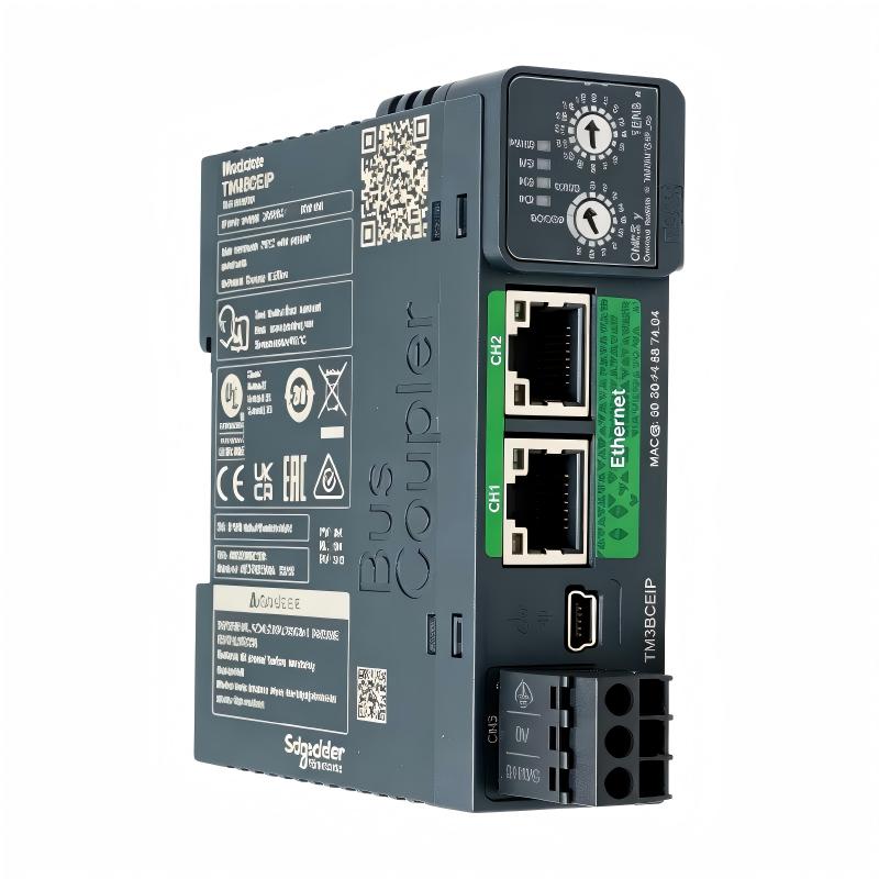
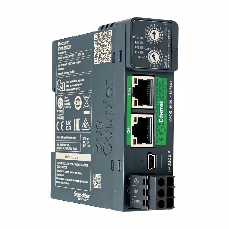
The Schneider Electric TM3BCEIP is a distributed I/O bus coupler module designed for the Modicon TM3 automation system. It provides an Ethernet communication interface that allows compatible controllers to exchange data with distributed I/O modules installed in a remote I/O island.
In modern industrial automation, control equipment and field devices are not always installed in the same cabinet. Distributed I/O architecture allows input and output modules to be located closer to sensors, actuators, and machinery, reducing the need to route every field signal back to a central control panel. The TM3BCEIP supports this architecture by connecting a compatible Ethernet-based control network to a group of TM3 expansion modules.
The module supports EtherNet/IP and Modbus TCP communication. It features two isolated RJ45 Ethernet ports that support daisy-chain network connections, along with a Mini-B USB device port for supported service and configuration functions. Ethernet communication supports 10/100 Mbps transmission, with half-duplex, full-duplex, and auto-negotiation modes.
The TM3BCEIP is designed for use with compatible Modicon M221, M241, M251, and M262 controller systems. It can support distributed I/O configurations that combine a bus coupler, expansion I/O modules, and the associated communication network. The number and type of modules permitted depend on the hardware configuration and applicable Schneider Electric system guidelines.
With its compact design, diagnostic indicators, and support for common industrial Ethernet protocols, the TM3BCEIP provides a practical interface for distributed automation applications in manufacturing, packaging, material handling, and machine control.
2. Technical Specifications
| Parameter | Specification |
|---|---|
| Brand | Schneider Electric |
| Model | TM3BCEIP |
| Product Series | Modicon TM3 |
| Product Type | Distributed I/O Bus Coupler Module |
| Main Function | Ethernet interface for distributed I/O |
| Supported Protocols | EtherNet/IP and Modbus TCP |
| Ethernet Ports | 2 isolated RJ45 ports |
| Ethernet Standard | 10/100BASE-T |
| Transmission Rate | 10/100 Mbps |
| Communication Modes | Half duplex, full duplex, auto-negotiation |
| Network Topology | Daisy chain; RSTP ring support is documented |
| USB Interface | Mini-B USB device port |
| Communication Services | EtherNet/IP adapter, Modbus TCP/IP server, DHCP client, BOOTP, SNMP, FTP server, web server and related services |
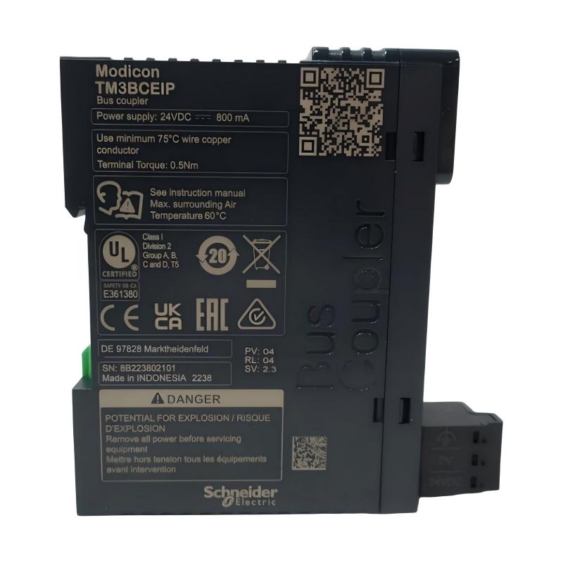
| Rated Internal Supply | 24 V DC |
| Maximum Internal Supply Current Consumption | 0.8 A at 24 V DC, with a maximum of 7 expansion modules under the specified configuration |
| Local Diagnostics | PWR, MS, NS and I/O status LEDs |
| Protection Rating | IP20 |
| Mounting | DIN rail or mounting plate, using the specified fixing method |
| Operating Temperature | -10°C to +60°C |
| Storage Temperature | -25°C to +70°C |
| Operating Altitude | 0–2,000 m |
| Storage Altitude | 0–3,000 m |
| Relative Humidity | 10–95%, non-condensing |
| Dimensions (H × W × D) | Approximately 96.5 × 27 × 70 mm |
| Net Weight | Approximately 0.10 kg |
| Supplied Product Identity | Modicon TM3 distributed I/O bus coupler |
Dimension note: The dimensions above refer to the product itself. The supplied dimensions of 125 × 104 × 74 mm may represent the packaged unit and should be confirmed against the specific shipping label or sales listing.
3. Function and Working Principle
The TM3BCEIP acts as a communication gateway between a compatible industrial Ethernet network and a distributed group of TM3 I/O modules. It enables the controller to exchange I/O data with remote modules without requiring all I/O hardware to be installed directly beside the PLC.
3.1 Distributed I/O Communication
In a distributed I/O arrangement, a controller communicates with a remote I/O station over an industrial Ethernet network. The remote station contains the bus coupler and supported expansion modules.
The TM3BCEIP manages the communication interface for the distributed I/O station. Input data acquired by compatible I/O modules can be transferred to the controller, while output commands from the controller can be delivered to the relevant output modules.
The exact data exchange behavior depends on the selected communication protocol, controller configuration, module arrangement, and application program.
3.2 EtherNet/IP Communication
EtherNet/IP is an industrial communication protocol used to exchange control and device information over Ethernet infrastructure.
The TM3BCEIP supports EtherNet/IP adapter functionality. When configured within a compatible control system, it allows an appropriate EtherNet/IP scanner or controller to communicate with the distributed I/O station.
Network configuration must follow the requirements of the controller, engineering software, and communication architecture. The module should not be assumed to support every feature or configuration available in all EtherNet/IP systems.
3.3 Modbus TCP Communication
The TM3BCEIP also supports Modbus TCP/IP server functionality. This allows compatible Modbus TCP clients to communicate with the distributed I/O station according to the supported data mapping and configuration.
Modbus TCP is commonly used for communication between PLCs, industrial computers, supervisory systems, and automation devices. Its use can simplify integration where the wider control architecture already relies on Modbus TCP.
Before commissioning, engineers should verify the supported register mapping, data representation, update behavior, and communication settings for the selected application.
3.4 Ethernet Daisy-Chain Connectivity
The module includes two isolated RJ45 Ethernet ports intended to support daisy-chain connections. This arrangement can help connect compatible Ethernet devices without requiring a separate switch for every connection point.
Daisy-chain topology can simplify wiring in certain machine layouts. However, the actual network design must account for cable length, network traffic, device compatibility, fault recovery, and the selected protocol.
The product documentation also identifies RSTP ring-topology support. The use of a ring must follow the relevant Schneider Electric network configuration instructions and the capabilities of the other devices in the network.
3.5 Status Monitoring and Diagnostics
The TM3BCEIP includes local status indicators for system power, module status, network status, and I/O status.
These indicators help maintenance personnel identify whether the module is powered, whether the module is operating normally, and whether a communication or I/O condition requires further investigation.
LED status should be interpreted according to the product’s indicator table. A single LED color or state should not be used as the only basis for diagnosing a network fault.
4. Role in Industrial Control Systems
The TM3BCEIP plays an important role in automation architectures that use distributed I/O to connect field devices to a central controller.
4.1 Connecting Remote I/O Stations
A central PLC may control a machine with several physically separated operating sections. Installing compatible I/O modules near each section can reduce the amount of field wiring routed to the main cabinet.
The TM3BCEIP provides the Ethernet interface for a supported distributed TM3 I/O station. This allows the control system to exchange data with remote I/O hardware over the selected industrial network.
4.2 Reducing Field Wiring Complexity
Distributed I/O can help organize machine wiring by grouping signals close to their physical sources and destinations. Instead of routing every sensor and actuator cable to one central location, field signals can terminate at suitable local I/O modules.
The TM3BCEIP supports communication between the remote I/O station and the control network. The overall wiring benefit depends on machine layout, the number of field devices, network topology, and the design of the electrical cabinets.
4.3 Supporting Multiple Communication Architectures
Support for EtherNet/IP and Modbus TCP gives system designers options when integrating the distributed I/O station into an appropriate industrial Ethernet architecture.
Protocol selection should be based on the capabilities of the controller, engineering environment, communication requirements, and the rest of the network. Protocol support does not automatically guarantee compatibility with every controller or device.
4.4 Expanding Modular Automation Systems
The TM3BCEIP supports distributed configurations using compatible TM3 expansion modules and supported system components. This makes it useful when a machine requires additional I/O capacity at a location separate from the main controller.
The permitted module count depends on the selected arrangement, including whether supported transmitter and receiver components are used. Engineers should validate the complete configuration before installation.
4.5 Improving Maintenance Visibility
Local LEDs provide information about power, module operation, network status, and I/O status. Combined with controller diagnostics and network monitoring, these indicators can help maintenance personnel narrow down communication or hardware issues.
The module does not replace a complete diagnostic strategy. Network monitoring, application alarms, and appropriate maintenance procedures remain important for reliable operation.
5. Industrial Applications
5.1 Packaging Machinery
Packaging lines often contain multiple stations, including feeding, filling, sealing, labeling, and inspection. Sensors and actuators may be distributed across the machine.
A TM3BCEIP-based remote I/O station can collect signals from a local group of compatible I/O modules and communicate with the main control system over industrial Ethernet.
5.2 Material Handling and Conveyors
Conveyor systems can extend across long production areas or connect several machine sections. Distributed I/O can simplify signal collection at transfer points, motor-control cabinets, and sensor stations.
The TM3BCEIP can serve as the Ethernet communication interface for a supported remote I/O arrangement, subject to the requirements of the selected network and controller.
5.3 Automated Assembly Lines
Assembly systems may contain multiple workstations with sensors, pneumatic devices, indicators, and other control equipment. A distributed I/O architecture can group signals by station and reduce centralized wiring.
The TM3BCEIP supports the communication link between compatible TM3 I/O modules and the wider control network.
5.4 Machine Tools and Special-Purpose Equipment
Special-purpose machines may use separate control zones for loading, processing, inspection, and unloading. Remote I/O can help organize the hardware around those zones.
The TM3BCEIP may be used where the controller and I/O configuration support the required communication protocol and module arrangement.
5.5 Water and Utility Systems
Pumping stations, treatment skids, and utility equipment may have sensors and control devices spread across several cabinets. Distributed I/O can support organized signal acquisition and output control.
The TM3BCEIP can provide an Ethernet interface for compatible remote I/O modules. Environmental protection, electrical isolation, communication reliability, and process-safety requirements must be evaluated for the actual installation.
5.6 Building and Facility Equipment
Industrial facility systems may combine ventilation equipment, pumps, auxiliary machinery, and local control panels. Where the chosen PLC platform and communication architecture are compatible, distributed I/O can help connect local devices to a supervisory control system.
The TM3BCEIP should be selected only after confirming that the required protocols, I/O modules, and system configuration are supported.
6. Installation and System Integration
Correct installation and configuration are essential for stable communication between the TM3BCEIP, the controller, and the distributed I/O modules.
6.1 Verify Controller Compatibility
The Modicon TM3 product family is designed for supported Modicon M221, M241, M251, and M262 controller systems. Before selecting the TM3BCEIP, verify the exact controller model, firmware, engineering software, communication protocol, and supported distributed I/O architecture.
Compatibility should be confirmed at the system level rather than inferred solely from the fact that two products belong to the Modicon family.
6.2 Mounting and Cabinet Layout
The module supports mounting on a compatible DIN rail or mounting plate using the specified fixing arrangement.
Install the device inside an enclosure suitable for the industrial environment. Its IP20 rating means it is intended for installation where the required protection against dust, moisture, and physical contact is provided by the cabinet or surrounding equipment.
Provide sufficient space for Ethernet cables, the USB connection, module access, and maintenance. Avoid placing the module where excessive heat, vibration, or electrical interference could affect the installation.
6.3 Power Supply Requirements
The product documentation identifies a 24 V DC internal supply and a maximum current consumption of 0.8 A for the specified configuration with up to seven expansion modules.
The actual power arrangement must follow the system documentation. When designing the remote I/O station, account for the bus coupler and the power requirements of the connected modules. Do not assume that one current figure represents every possible module combination.
Verify polarity, supply capacity, wiring, and grounding before energizing the equipment.
6.4 Ethernet Network Wiring
Use suitable Ethernet cabling and connectors for the installation environment. Connect the module’s RJ45 ports according to the planned network topology.
When using a daisy-chain arrangement, confirm the permitted connection sequence and the requirements of all connected devices. When implementing an RSTP ring, follow the supported network design and configuration guidance.
Keep Ethernet cables away from sources of strong electrical interference where practical. Observe applicable cable-length, shielding, grounding, and industrial Ethernet installation requirements.
6.5 Configure the Communication Protocol
Select EtherNet/IP or Modbus TCP according to the intended control architecture and the capabilities of the connected controller or client.
The configuration process may include assigning network parameters, selecting the appropriate device profile or communication mapping, defining the I/O data exchange, and configuring the controller program.
Avoid duplicate IP addresses. Confirm that the subnet, network addressing, communication settings, and required services are consistent across the network.
6.6 Configure the Distributed I/O Station
Install only supported expansion modules and follow the recommended physical arrangement. The TM3BCEIP supports distributed I/O configurations, but the number of permitted modules depends on the selected hardware arrangement.
Schneider Electric documentation describes configurations supporting up to seven TM2/TM3 modules without transmitter and receiver components, and up to fourteen TM3 modules when the supported transmitter and receiver arrangement is used. The precise configuration must be validated against the applicable product documentation and power constraints.
6.7 Commissioning and Functional Testing
After installation, carry out a structured commissioning procedure:
- Verify the model number and physical installation.
- Check the 24 V DC supply and applicable power requirements.
- Confirm Ethernet cable connections and network addressing.
- Verify that the selected protocol is configured correctly.
- Confirm that the controller recognizes the distributed I/O station.
- Check the PWR, MS, NS, and I/O status indicators.
- Test input and output signals using a controlled procedure.
- Confirm that communication loss and recovery are handled appropriately by the application.
- Record the final hardware configuration and network settings for maintenance.
If communication fails, investigate power, cable connections, IP addressing, protocol configuration, module arrangement, and controller diagnostics before replacing hardware.
7. Compatible System Components
The TM3BCEIP is intended to be used as part of a supported distributed automation system.
| Component | Role in the System |
|---|---|
| Modicon M221 Logic Controller | Compatible controller platform for supported automation configurations |
| Modicon M241 Logic Controller | Controller platform for supported machine-control applications |
| Modicon M251 Logic Controller | Compatible controller platform for supported system configurations |
| Modicon M262 Logic Controller | Controller platform for supported automation and communication architectures |
| TM3 Digital Input Modules | Acquire discrete field signals such as switch and sensor states |
| TM3 Digital Output Modules | Provide discrete control signals to compatible field devices |
| TM3 Analog Input Modules | Acquire supported analog signals from field instruments |
| TM3 Analog Output Modules | Generate supported analog control signals |
| TM3 Transmitter and Receiver Modules | Support specific extended distributed I/O configurations |
| Industrial Ethernet Switch | Provides network connectivity where required by the network architecture |
| Ethernet Cables | Carry industrial network communication between supported devices |
| 24 V DC Power Supply | Provides power according to the system’s specified requirements |
| EcoStruxure Engineering Software | Used for supported hardware configuration, programming, and diagnostics |
The final combination of components must be checked for controller compatibility, communication protocol, firmware, power budget, module count, and physical installation requirements.
8. Recommended Alternative Models
The TM3BCEIP is a bus coupler rather than a conventional standalone I/O module. Alternative selection should therefore focus on communication architecture and distributed I/O requirements rather than simply matching the number of input or output channels.
| Model or Product Category | Description | Selection Consideration |
|---|---|---|
| Schneider TM3BCEIP | Ethernet bus coupler for distributed TM3 I/O | Reference model for EtherNet/IP and Modbus TCP distributed I/O |
| Schneider TM3BCSL | TM3 bus coupler for supported Modicon system configurations | Evaluate when a different bus-coupling architecture is required |
| Schneider TM3 Transmitter/Receiver Modules | Components used in supported extended TM3 I/O arrangements | Consider when the required distributed configuration exceeds the direct arrangement’s limits |
| Schneider TM3 Digital Input Modules | Modules for acquiring discrete signals | Suitable for adding input channels, not as a replacement for the bus coupler |
| Schneider TM3 Digital Output Modules | Modules for controlling discrete loads | Suitable for output expansion, not as a direct bus-coupler replacement |
| Schneider TM3 Analog Input Modules | Modules for analog measurement | Select according to signal range, channel count, and accuracy requirements |
| Schneider TM3 Analog Output Modules | Modules for analog control commands | Select according to signal type and output requirements |
These products do not all provide the same function as the TM3BCEIP. Before substituting a component, verify protocol support, controller compatibility, expansion limits, and the intended system architecture.
9. Key Advantages
Industrial Ethernet Connectivity
The TM3BCEIP supports EtherNet/IP and Modbus TCP, providing communication options for compatible industrial automation systems.
Distributed I/O Architecture
It allows supported TM3 I/O modules to be organized in a remote I/O station, helping place signal interfaces closer to field devices.
Two Ethernet Ports
The two isolated RJ45 ports support daisy-chain connectivity and can simplify network wiring in suitable installations.
Diagnostic Indicators
PWR, MS, NS, and I/O status LEDs provide local information that can help engineers identify power, module, network, or I/O conditions.
Compact Design
The module measures approximately 96.5 × 27 × 70 mm and weighs about 0.10 kg, making it suitable for compact control-panel and distributed I/O installations.
Flexible System Expansion
The TM3BCEIP supports distributed I/O arrangements using compatible TM3 expansion modules. The available expansion capacity depends on the chosen configuration and the applicable system limits.
Web and Network Services
The module documentation identifies services including web access, DHCP client, BOOTP, SNMP, FTP server, and other communication functions. Available services and their configuration should be checked against the relevant product documentation and system security requirements.
10. Technical FAQs
Q1: What is the Schneider TM3BCEIP?
The TM3BCEIP is a Schneider Electric Modicon TM3 distributed I/O bus coupler module. It provides an Ethernet interface for compatible remote I/O configurations.
Q2: Which communication protocols does it support?
The module supports EtherNet/IP and Modbus TCP. The selected protocol must be compatible with the controller, client, engineering software, and overall network design.
Q3: What are the Ethernet port specifications?
The TM3BCEIP has two isolated RJ45 Ethernet ports supporting 10/100BASE-T communication at 10/100 Mbps. The ports support daisy-chain connectivity.
Q4: Does the TM3BCEIP support USB?
Yes. It includes a Mini-B USB device port for supported service and configuration functions. Refer to the product documentation for the applicable connection and software requirements.
Q5: Which Modicon controllers can be used with the TM3BCEIP?
The Modicon TM3 range is designed for compatible M221, M241, M251, and M262 controller systems. The exact controller and communication configuration should be verified before installation.
Q6: How many expansion modules can be connected?
The supported module count depends on the configuration. Schneider Electric documentation describes up to seven TM2/TM3 modules without transmitter and receiver components, and up to fourteen TM3 modules with a supported transmitter and receiver arrangement. Power requirements and system limits must also be checked.
Q7: What is the power requirement?
The product documentation identifies a 24 V DC internal supply and maximum current consumption of 0.8 A for the specified configuration with up to seven expansion modules. The power design must account for the actual installed system.
Q8: What are the dimensions and weight?
The product’s documented dimensions are approximately 96.5 mm high, 27 mm wide, and 70 mm deep. Its net weight is approximately 0.10 kg.
Q9: Is the TM3BCEIP an analog input or output module?
No. It is a distributed I/O bus coupler. Analog input and output functions are provided by compatible expansion modules connected within the supported I/O arrangement.
Q10: Can the TM3BCEIP be connected directly to an Ethernet switch?
Its RJ45 Ethernet ports can be incorporated into a compatible Ethernet network. The connection arrangement, network topology, addressing, and protocol configuration must follow the product and system documentation.
Q11: What does the NS LED indicate?
The NS indicator is the network status LED. Its specific colors and flashing patterns should be interpreted using the official indicator table for the TM3BCEIP.
Q12: Is the TM3BCEIP suitable for outdoor installation?
The module has an IP20 protection rating and an operating temperature range of -10°C to +60°C. It should be installed in an enclosure that provides the environmental protection required by the application.
11. Conclusion
The Schneider Electric TM3BCEIP is an Ethernet bus coupler designed to connect compatible Modicon TM3 distributed I/O modules to an industrial automation network. Support for EtherNet/IP and Modbus TCP, two isolated RJ45 Ethernet ports, diagnostic indicators, and compact dimensions make it a useful component in supported distributed control architectures.
By placing I/O modules closer to field devices, a distributed I/O system can help organize machine wiring and support modular equipment layouts. Successful implementation depends on selecting a compatible controller, choosing the appropriate communication protocol, validating the module arrangement, and following the specified power, wiring, and network requirements.
For purchasing and maintenance purposes, confirm the full model number, product dimensions, weight, terminal and port configuration, and compatibility requirements before replacing or integrating the TM3BCEIP.