

ProductPRODUCT
Featured products
Contact Us
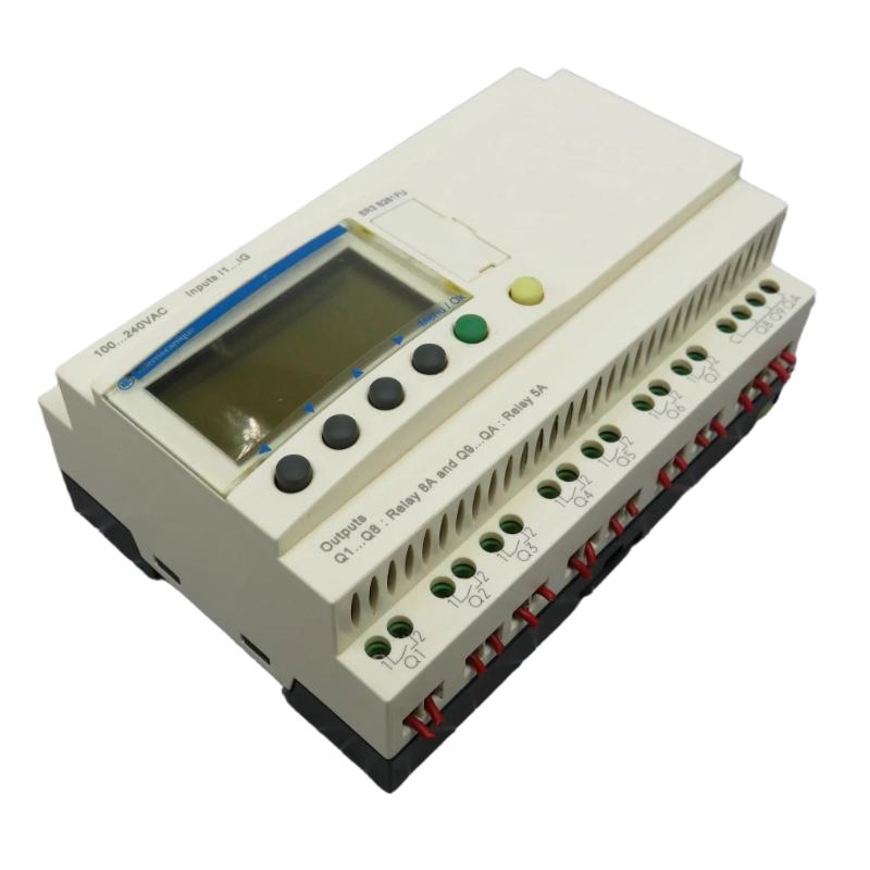
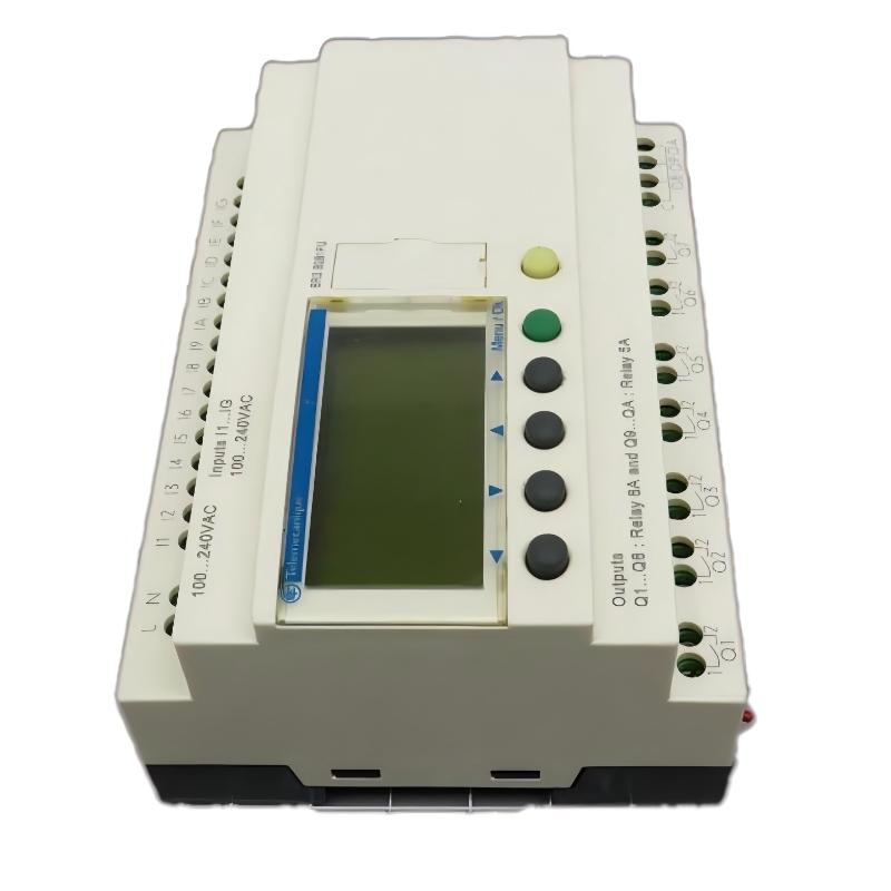
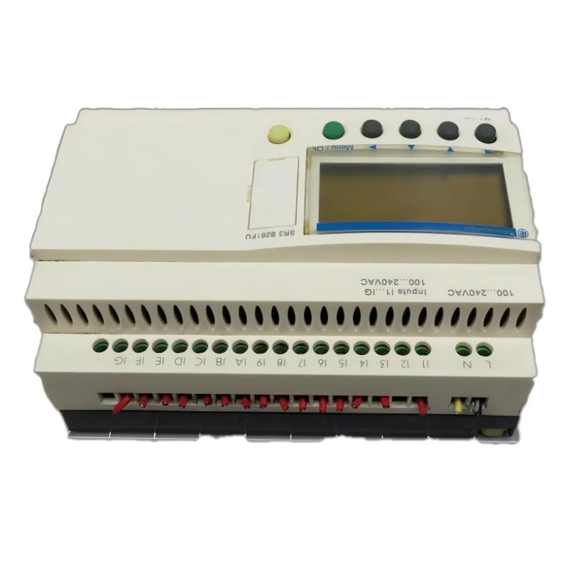
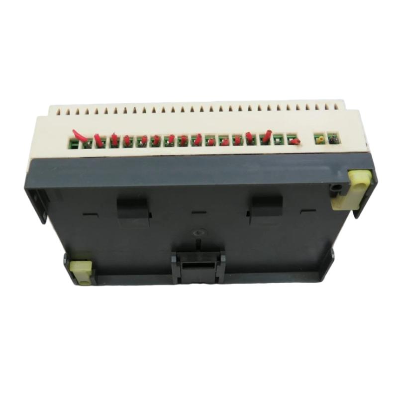
- Schneider
- SR3B261FU
- Modular Smart Relay
- France
- 124.6 x 107.6 x 59.5 mm
- 0.4 kg
- Xiamen, China
- New & In Stock
- T/T, PayPal, Western Union
- 1 Year
- 1-3 Working Days
- DHL, UPS, TNT, FedEx and EMS.
- 24-Hour Service
- COO
- 6
Our advantage

Global Logistics
We have a 10-year logistics and express cooperation agreement, so our products can be shipped to any place in the world.

Brand new and original
Our products are imported in bulk from the place of origin. Because of the cooperative relationship, our products are all original and 100% new.

24-hour service
We provide 7*24 hours service to our customers. We will be there whenever you need us.

Price advantage
All our products are priced very favorably because we have our own warehouse and supply.
| Company Information | |||
| [email protected] | |||
| Mobile | +8615980777398 | ||
| +8615980777398 | |||
| 15980777398 |
Product Overview
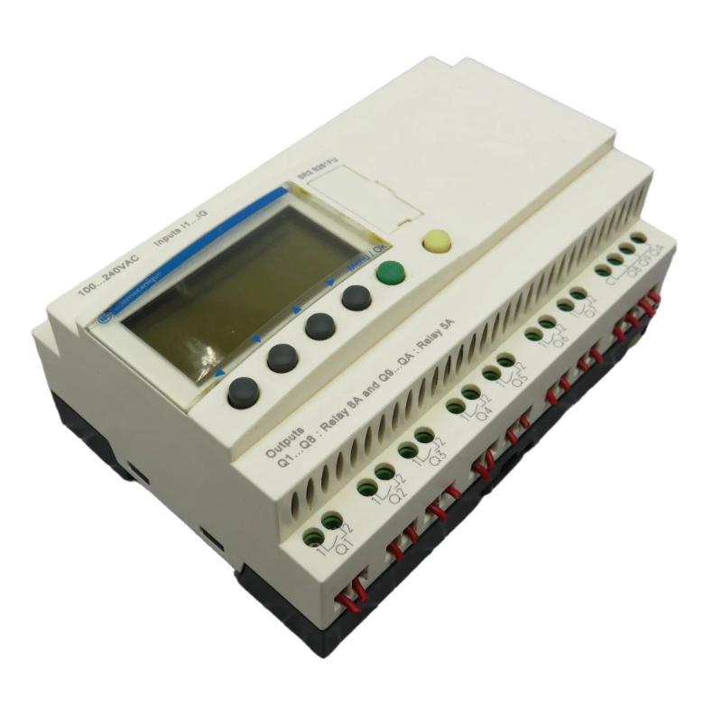
The Schneider Electric SR3B261FU Modular Smart Relay is an industrial control device designed to support compact automation tasks involving discrete signal processing, programmable logic, and equipment sequencing. Modular smart relays are commonly used in applications where a dedicated programmable controller would be more complex than necessary, but conventional relay logic would lack the flexibility required for reliable and adaptable operation.
A smart relay combines control logic with input and output interfaces in a compact unit. It can process signals from switches, sensors, push buttons, and other compatible field devices, then execute a programmed sequence to operate connected equipment. Typical applications include lighting control, pump management, ventilation systems, small machines, access-control logic, and auxiliary equipment automation.
The Schneider Electric SR3B261FU belongs to the SR3 modular smart relay product designation. Its listed dimensions are 124.6 × 107.6 × 59.5 mm, with a listed weight of 0.4 kg. This compact form factor is suitable for control-panel designs where space efficiency and straightforward wiring are important considerations.
Before installation, the exact model suffix and electrical specifications should be checked against the unit’s identification label and applicable technical documentation. Supply voltage, input and output characteristics, communication options, expansion compatibility, and programming requirements should not be inferred from the model name alone.
Technical Specifications
| Parameter | Specification |
|---|---|
| Manufacturer | Schneider Electric |
| Model | SR3B261FU |
| Product Type | Modular Smart Relay |
| Product Category | Programmable Relay / Compact Automation Controller |
| Primary Function | Programmable logic and discrete equipment control |
| Control Method | User-configured logic program |
| Signal Processing | Discrete input and output processing, subject to model specifications |
| Dimensions | 124.6 × 107.6 × 59.5 mm |
| Weight | 0.4 kg |
| Installation | Control-panel installation; confirm the specified mounting method |
| Programming | Compatible programming environment for the verified model |
| Typical Applications | Small machines, lighting, pumps, ventilation, and auxiliary automation |
| Expansion Compatibility | Verify supported expansion modules and configuration limits |
| Electrical Specifications | Confirm the exact supply and I/O ratings before installation |
The physical dimensions and weight above are based on the supplied product information. The exact supply voltage, number and type of inputs and outputs, output ratings, programming interface, and expansion capabilities should be verified for the complete SR3B261FU designation before procurement or commissioning.
What Is the Schneider SR3B261FU Modular Smart Relay?
A modular smart relay is a compact programmable controller intended for relatively straightforward automation tasks. It combines logic processing and field-device interfacing in a single device or a compact modular assembly.
In a traditional relay-control circuit, system behavior is determined by the physical arrangement of relay contacts, timers, and auxiliary devices. Changing the control sequence may require substantial rewiring. A smart relay replaces much of this hardwired logic with a configurable program, allowing supported control functions to be modified without redesigning the entire circuit.
The SR3B261FU is identified as a modular smart relay. Within a compatible control system, its role is to receive input conditions, evaluate the programmed logic, and update outputs according to the application’s requirements.
A simplified control sequence is:
Field Inputs → Smart Relay Logic → Output Commands → Controlled Equipment
For example, a control program may require a pump to operate only when a start command is present and a permissive condition is satisfied. The smart relay evaluates the relevant input states and issues an output command when the programmed conditions are met.
The actual logic, electrical connections, and supported functions depend on the verified model specifications and the application design.
Function and Working Principle
1. Input Signal Acquisition
The smart relay receives electrical signals from compatible field devices. These may include push buttons, selector switches, limit switches, float switches, auxiliary contacts, and discrete sensors.
Input signals communicate the current status of the equipment or provide commands from an operator. For example, a start push button can request operation, while a limit switch can indicate that a mechanism has reached a defined position.
The field-device voltage and wiring arrangement must match the relay’s input specifications. Incorrect wiring or incompatible electrical signals can result in unreliable operation or equipment damage.
2. Programmable Logic Processing
After receiving input states, the smart relay evaluates its configured control program. Depending on the supported programming functions, the program may contain logic operations, timers, counters, interlocks, and sequential conditions.
This allows several input signals to be combined into a single control decision. A motor output, for instance, may be permitted only when a start command is present and the required operating conditions have been satisfied.
The specific instructions and programming features available must be confirmed for the exact model.
3. Output Control
When the programmed conditions are met, the smart relay updates its outputs. Depending on the verified hardware configuration, outputs may be used to operate compatible interface relays, contactors, indicator lamps, or other control devices.
Loads must remain within the output ratings specified for the device. Where a load exceeds the permitted rating or requires electrical isolation, a suitable external interface device should be used.
4. Timing and Sequence Management
Many smart-relay applications involve actions that must occur in a particular order or after a defined delay. Where supported by the model, timers and related logic functions can coordinate these operations.
For example, a ventilation system may require a delayed shutdown, while a pump sequence may require a waiting period between control stages. These functions can reduce the amount of external timing hardware required.
5. Repeated Automatic Operation
Once configured and commissioned, the smart relay repeatedly evaluates input states and updates outputs according to its program. This supports consistent operation without requiring an operator to execute each control step manually.
The controller’s response still depends on correct wiring, suitable programming, reliable field devices, and the operating limits of the connected equipment.
Role in Industrial Control Systems
The SR3B261FU can serve as a compact control element in a broader industrial automation architecture. Its intended role is to handle local control tasks where a programmable relay provides a suitable balance between functionality, installation effort, and system complexity.
In a typical installation, the smart relay receives signals from field devices and controls connected loads through its output interface. An operator may interact with the system through push buttons or selector switches, while auxiliary devices provide feedback about operating conditions.
| System Component | Typical Function |
|---|---|
| Schneider Electric Smart Relay | Executes the configured control logic |
| Push Buttons | Provide manual start, stop, and reset commands |
| Selector Switches | Select operating modes |
| Limit Switches | Detect position or travel limits |
| Compatible Sensors | Provide discrete process or equipment status |
| Interface Relays | Provide suitable switching interfaces where required |
| Contactors | Switch motors and other appropriate power loads |
| Circuit Protection | Protects circuits according to the electrical design |
| Indicator Lamps | Display operating states and fault conditions |
| Control Cabinet | Houses and protects the control equipment |
The specific components required depend on the application. The smart relay should not be assumed to replace dedicated safety controllers, motor protection devices, or other specialized control equipment.
Industrial Applications
Pump Control
A smart relay can support straightforward pump-control sequences when the connected devices and control design are suitable. Inputs may indicate a start request, a float-switch state, or an equipment permissive condition. The programmed logic can then determine when a pump command should be issued.
Additional protection, motor overload handling, and independent safety measures should be provided as required by the installation.
Ventilation and Fan Control
Small ventilation systems may require start/stop control, operating delays, mode selection, or coordination with other equipment. A programmable relay can consolidate these functions into a compact control unit.
The application should account for motor starting equipment, electrical ratings, and the required response to abnormal conditions.
Lighting Automation
Lighting circuits may require scheduled sequences, manual overrides, grouped switching, or operation based on external switches and sensors. A smart relay can provide programmable switching logic when its output characteristics are suitable for the connected loads.
External switching devices may be necessary for loads that exceed the relay’s direct output ratings.
Small Machinery
Compact machinery often uses discrete signals to confirm positions, process operator commands, and coordinate short operating sequences. A smart relay can handle these tasks where the sequence complexity and response requirements fit the capabilities of the device.
Applications involving complex motion, high-speed control, or specialized safety requirements may need a different controller architecture.
Auxiliary Equipment Control
Smart relays are useful for auxiliary equipment such as small utility systems, local ventilation units, indicator circuits, and simple transfer sequences. They can help reduce hardwired logic and make control behavior easier to revise during maintenance or process changes.
Building and Facility Automation
Selected building-control tasks can be implemented with programmable relays, including simple equipment sequencing and discrete status monitoring. The suitability of the SR3B261FU depends on its verified electrical ratings, environmental limits, and available control functions.
Installation and System Integration
Correct installation is essential for reliable operation. Before integrating the SR3B261FU, verify its complete designation, supply requirements, wiring arrangement, and compatibility with the intended application.
Confirm the Model and Supply Requirements
Check the identification label and confirm the complete SR3B261FU model number. Verify the permitted supply voltage and frequency, terminal arrangement, and grounding requirements.
Do not energize the unit until the supply requirements have been confirmed. A similar product designation does not guarantee an identical electrical configuration.
Prepare the Control Panel
Install the smart relay using the mounting method specified for the exact product. Provide adequate space for wiring, inspection, ventilation, and servicing.
The panel should protect the device from excessive dust, moisture, vibration, and temperature. Keep wiring organized and route signal conductors appropriately in relation to power wiring.
Connect Input Devices
Connect switches and sensors according to the correct terminal diagram. Label each input conductor and document the field device associated with each input.
Check signal polarity, common connections, and voltage compatibility before applying power. Never assume that terminal assignments are identical across different smart-relay variants.
Connect Output Loads
Confirm the output type and ratings before connecting a load. Motors, solenoids, contactor coils, and other inductive loads may require external switching devices or suppression components, depending on their characteristics and the relay’s specifications.
Use appropriate overcurrent protection and ensure that wiring, terminals, and external devices are rated for the intended circuit.
Develop and Verify the Program
Create the control logic using the programming environment supported by the verified model. Define the intended operating sequence, input conditions, output actions, timing requirements, and fault responses.
Review the program before commissioning. Where practical, test the logic under controlled conditions before allowing the connected machinery to operate normally.
Commission the System
During commissioning, verify the supply, input states, output actions, and overall sequence. Test normal operation as well as expected abnormal conditions, such as loss of a permissive signal or activation of a stop command.
Record the final program version, wiring information, and relevant configuration details. These records simplify future maintenance and reduce the risk of configuration errors during replacement.
Troubleshooting the SR3B261FU
When the smart relay does not operate as expected, investigate the power supply, input wiring, program logic, output circuit, and connected equipment systematically.
The Smart Relay Does Not Power Up
Possible causes include an incorrect supply, missing power, a loose connection, a damaged conductor, or an internal device fault.
Check the supply against the verified product specification and inspect the wiring. If the correct supply is present but the unit remains inactive, follow the manufacturer’s diagnostic and replacement procedures.
Input Signals Are Not Detected
An input may fail to change state because of a defective field device, open wiring, incorrect terminal assignment, incompatible voltage, or an incorrect common connection.
Check the field device’s operation and verify the electrical signal at the relevant input using an appropriate instrument. Compare the result with the device’s specified input requirements.
Outputs Do Not Operate
If the input states appear correct but the output does not activate, inspect the control program, output assignment, interlock conditions, and output wiring.
Also verify that the connected load is compatible with the output type and rating. An external relay, contactor, fuse, or other component may be responsible for the failure rather than the smart relay itself.
Unexpected Control Sequence
Unexpected behavior may be caused by incorrect logic, an unanticipated input state, unsuitable timer settings, an unintended mode selection, or a wiring error.
Review the program against the intended operating sequence. Test individual conditions in a controlled environment and confirm that the programmed response matches the documented requirements.
Intermittent Operation
Intermittent faults can result from loose terminals, damaged cables, unstable power, electrical interference, failing switches, or loads that exceed the permitted output characteristics.
Inspect the wiring and field devices, check the control-panel environment, and review any available status or diagnostic information. Record when the fault occurs to help identify whether it is related to temperature, vibration, switching events, or a particular sequence.
Maintenance Recommendations
Regular inspection helps maintain dependable operation and makes faults easier to diagnose.
Inspect wiring and terminals. Look for loose connections, damaged insulation, corrosion, and signs of overheating. Tighten terminals according to the specified requirements.
Check field devices. Verify the operation of push buttons, switches, and sensors connected to the smart relay.
Review the control program. Keep a backup of the approved program and document any modifications to logic, timing, or input/output assignments.
Monitor operating conditions. Maintain the panel within the specified environmental limits and address excessive heat, moisture, dust, or vibration.
Check output loads. Confirm that connected devices remain within the relay’s rated output limits and that external interface components are functioning correctly.
Maintain replacement records. Record the complete model number, wiring arrangement, program version, and commissioning results to support future servicing.
Maintenance intervals should reflect the operating environment, application requirements, and equipment manufacturer’s recommendations.
Compatible System Components
The SR3B261FU may be used in an automation arrangement containing several types of control and interface components. The following table identifies general component categories rather than confirming compatibility with every specific model.
| Component Category | Purpose |
|---|---|
| Compatible Schneider Electric Programming Tools | Configure and maintain supported control logic |
| Push Buttons and Selector Switches | Provide operator commands |
| Discrete Sensors | Detect equipment or process conditions |
| Interface Relays | Adapt switching interfaces when required |
| Contactors | Switch suitable power circuits |
| Circuit Protection Devices | Protect wiring and equipment |
| Terminal Blocks | Organize control wiring |
| Indicator Lamps | Display status and alarm conditions |
| Industrial Control Power Supply | Provides the required electrical supply where applicable |
| Enclosure and Mounting Accessories | Support secure panel installation |
Before selecting a programming cable, expansion unit, accessory, or replacement controller, confirm the exact SR3B261FU specifications and supported configuration. Physical similarity or a shared product family does not establish electrical compatibility.
Replacement and Procurement Considerations
When sourcing the Schneider Electric SR3B261FU Modular Smart Relay, verify the full model number against the existing device and the application’s technical requirements.
Important checks include:
- Complete product designation
- Supply voltage and frequency
- Input type and electrical ratings
- Output type and load ratings
- Supported programming method
- Expansion and accessory compatibility
- Terminal layout and mounting requirements
- Product condition and available test records
The supplied physical specifications are 124.6 × 107.6 × 59.5 mm and 0.4 kg. These values are useful for inventory planning, shipping estimates, and preliminary panel-layout preparation, but they are not sufficient to establish electrical interchangeability.
When replacing an installed smart relay, document the original wiring and program before removing the unit. After fitting the replacement, verify the configuration and test all required operating sequences before returning the equipment to service.
Key Advantages
Compact Programmable Control
A smart relay can consolidate multiple simple control functions into a compact device, reducing the need for extensive hardwired relay logic in suitable applications.
Flexible Sequence Configuration
Programmable logic allows supported control sequences to be adjusted through configuration changes rather than requiring every modification to be implemented through physical rewiring.
Simplified Local Automation
For small machines and auxiliary equipment, a smart relay can provide a practical way to coordinate discrete signals and control actions.
Organized Control-Panel Integration
The listed dimensions of 124.6 × 107.6 × 59.5 mm and weight of 0.4 kg support preliminary space and handling assessments when designing or maintaining an appropriate control panel.
Easier Troubleshooting and Documentation
Clear input/output assignments, a backed-up control program, and recorded commissioning tests can make fault diagnosis and maintenance more efficient.
Technical FAQs
What is the Schneider SR3B261FU?
The SR3B261FU is identified as a Schneider Electric modular smart relay intended for programmable control tasks in suitable industrial and building-automation applications.
What is a modular smart relay used for?
A modular smart relay processes discrete inputs and executes configured logic to control connected outputs. Common applications include small machinery, lighting, ventilation, pumps, and auxiliary equipment.
What are the dimensions of the SR3B261FU?
The supplied dimensions are 124.6 × 107.6 × 59.5 mm.
What is the weight of the SR3B261FU?
The supplied weight is 0.4 kg.
Can the SR3B261FU control a motor directly?
That depends on the verified output type and electrical ratings, as well as the motor’s characteristics. Motor circuits commonly require appropriately rated contactors, overload protection, and other protective devices. Confirm the design before connecting any motor load.
Can it be integrated with expansion modules?
Expansion compatibility and configuration limits must be confirmed for the exact product designation. Do not assume that every module in a related product family can be attached.
What causes a smart relay to execute the wrong sequence?
Potential causes include incorrect program logic, unexpected input states, wiring errors, unsuitable timer settings, or faulty field devices. Troubleshooting should begin with the intended sequence and the actual input/output states.
What should be checked before replacing the relay?
Verify the complete model number, electrical supply, input/output specifications, terminal arrangement, program requirements, and compatibility with the existing system. Record the current wiring and program before removing the original device.
Conclusion
The Schneider Electric SR3B261FU Modular Smart Relay is intended to provide compact programmable control for suitable industrial automation and equipment-management tasks. By processing discrete input signals and executing configured logic, a smart relay can coordinate equipment sequences, manage local switching functions, and reduce the complexity of conventional hardwired control circuits.
With supplied dimensions of 124.6 × 107.6 × 59.5 mm and a weight of 0.4 kg, the SR3B261FU can be considered for compact control-panel applications where its verified electrical and functional capabilities meet the system requirements.
Reliable operation depends on correct model identification, compatible field devices, appropriate output-load selection, accurate programming, and systematic commissioning. Before installation or replacement, confirm the exact product specifications and ensure that the control design includes the protection and safety functions required by the application.