

ProductPRODUCT
Featured products
Contact Us
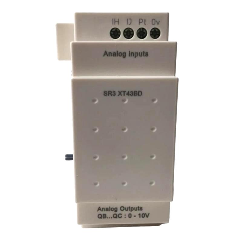
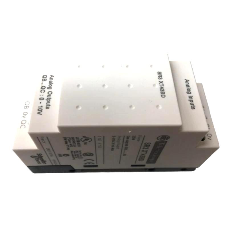
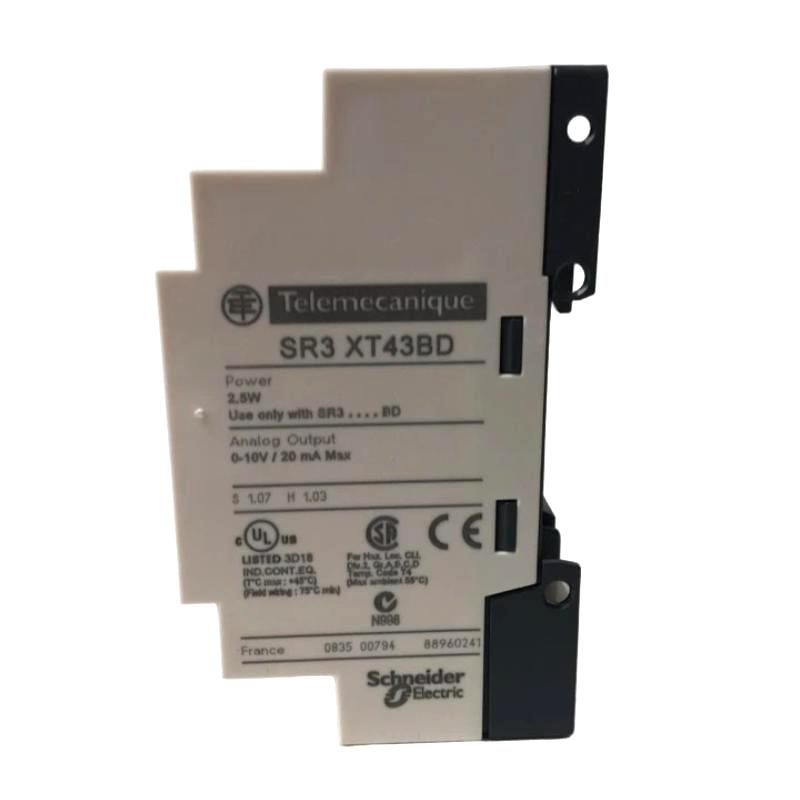
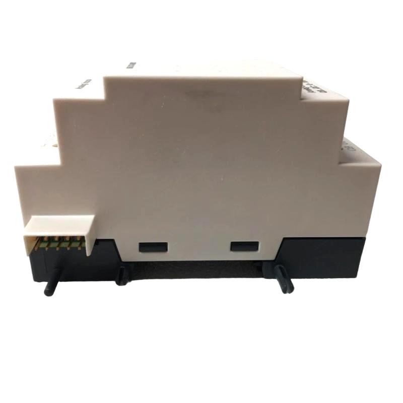
- Schneider
- SR3XT43BD
- Analog I/O Expansion Module
- France
- 107.6 x 35.5 x 59.5 mm
- 0.11 kg
- Xiamen, China
- New & In Stock
- T/T, PayPal, Western Union
- 1 Year
- 1-3 Working Days
- DHL, UPS, TNT, FedEx and EMS.
- 24-Hour Service
- COO
- 2
Our advantage

Global Logistics
We have a 10-year logistics and express cooperation agreement, so our products can be shipped to any place in the world.

Brand new and original
Our products are imported in bulk from the place of origin. Because of the cooperative relationship, our products are all original and 100% new.

24-hour service
We provide 7*24 hours service to our customers. We will be there whenever you need us.

Price advantage
All our products are priced very favorably because we have our own warehouse and supply.
| Company Information | |||
| [email protected] | |||
| Mobile | +8615980777398 | ||
| +8615980777398 | |||
| 15980777398 |
Product Overview
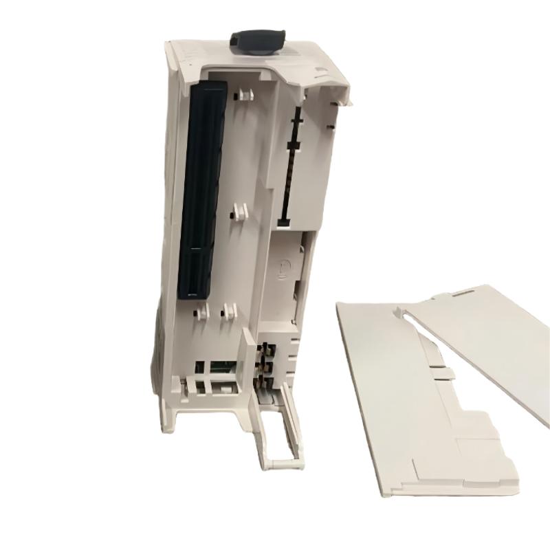
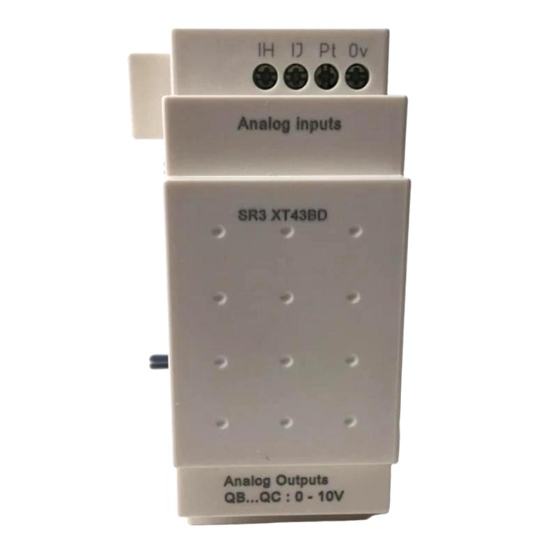
The Schneider Electric SR3XT43BD Analog I/O Expansion Module is an industrial automation expansion component designed to extend the input and output capabilities of a compatible control system. Analog expansion modules are used when an automation application requires additional measurement or control signals beyond the resources available on the main controller or smart relay.
In industrial environments, many process variables change continuously rather than switching between simple ON and OFF states. Examples include temperature, pressure, liquid level, flow rate, and other measured conditions. Analog input interfaces allow compatible controllers to acquire these varying signals, while analog output interfaces can provide control references to suitable external equipment. The exact signal types and electrical ranges depend on the module’s verified specifications.
The SR3XT43BD model is identified in the supplied product description as an analog I/O expansion module within Schneider Electric’s industrial control product range. Its listed dimensions are 107.6 × 35.5 × 59.5 mm, and its listed weight is 0.11 kg. Its compact size can help support space-efficient control-panel layouts.
Before installation, confirm the complete reference and its compatibility with the intended Schneider Electric controller or smart relay. The supported analog channel configuration, signal ranges, connection terminals, power requirements, and software configuration should be verified against the exact product documentation rather than inferred from the model name.
Technical Specifications
| Parameter | Specification |
|---|---|
| Manufacturer | Schneider Electric |
| Model | SR3XT43BD |
| Product Type | Analog I/O Expansion Module, as supplied |
| Product Category | Industrial Automation / Control Expansion |
| Primary Function | Expansion of compatible analog input and output capabilities |
| Signal Type | Analog signals; supported electrical ranges require verification |
| System Role | Additional process-signal interface for a compatible controller |
| Dimensions | 107.6 × 35.5 × 59.5 mm |
| Weight | 0.11 kg |
| Installation | Verify mounting and connection requirements for the exact model |
| Typical Applications | Process monitoring, machine automation, and industrial control |
| Compatibility | Confirm the supported controller family and hardware configuration |
Technical verification note: The model designation and supplied description should be checked against the original product label. The table records the provided product information but does not assume an unverified number of channels, voltage or current ranges, resolution, accuracy, or supported communication functions.
What Is the Schneider SR3XT43BD?
An analog I/O expansion module is intended to add process-signal handling capability to a compatible automation controller. It can support applications where the control system needs to monitor varying process conditions or generate an analog control reference.
A digital signal typically represents a discrete state, such as a switch being open or closed. An analog signal, by contrast, represents a value that can vary over a defined range. For example, a suitable temperature transmitter may provide a signal corresponding to measured temperature, while a compatible pressure transmitter may represent changes in system pressure.
When an analog expansion module is supported by the controller, the acquired signal can be made available to the control program. The program can then compare the measured value with configured limits, display process information, activate alarms, or calculate a control response.
A simplified automation sequence is:
Process Sensor → Analog Input Interface → Controller Logic → Analog Output Interface → Compatible Control Device
This diagram illustrates a general analog control arrangement. The actual signal path depends on the verified capabilities of the SR3XT43BD and the connected hardware.
Function and Working Principle
1. Analog Signal Acquisition
Analog input hardware receives a compatible electrical signal from a field instrument. The signal may represent a measured process variable, such as temperature, pressure, level, or flow.
The module and field instrument must use compatible signal types and electrical ranges. Wiring configuration, signal polarity, grounding, and any required external power supply must be checked before commissioning.
2. Signal Conversion and Processing
In a typical analog input system, electronic circuitry conditions the incoming signal and converts it into numerical data that the controller can process. The implementation, resolution, accuracy, and conversion characteristics vary by product.
The resulting value can be used by the controller program for monitoring, calculations, alarm conditions, or process regulation. Actual conversion specifications for the SR3XT43BD must be confirmed from the correct product documentation.
3. Controller-Level Processing
The controller evaluates the acquired process value according to the configured application logic. For example, a program may compare a measured value with a setpoint or determine whether a process variable has exceeded an operating threshold.
The controller is responsible for executing the configured logic. An expansion module supplies the relevant signal interface but does not independently determine the full process-control strategy.
4. Analog Output Generation
Where the installed expansion hardware provides analog output functionality, the controller may command a compatible output signal for external equipment. Depending on the verified interface and application, an analog reference can be used by a compatible drive, positioning device, or other control interface.
The output signal type, electrical range, loading limits, and isolation characteristics must be checked before connecting an external device. The supplied product description alone does not establish these specific capabilities for the SR3XT43BD.
5. Continuous Process Monitoring
Analog measurements can provide a more detailed view of changing process conditions than simple discrete status signals. When properly configured, the control system can use these measurements to identify trends, monitor operating limits, and coordinate process responses.
Role in Industrial Control Systems
An analog expansion module contributes to the interface between process instrumentation and control logic. In a compact automation system, the main controller may handle sequencing and decision-making, while compatible expansion modules provide additional interfaces for field devices.
The module’s potential role in an automation architecture can be summarized as follows:
- Receive supported process signals.
- Make compatible measurements available to the controller.
- Support application-specific monitoring and control logic.
- Help integrate additional instrumentation into an existing control installation.
- Reduce the need to redesign an entire control panel when more supported I/O capability is required.
The actual functions available depend on the confirmed model, controller family, and installed configuration.
Industrial Applications
Process Monitoring
Analog signal interfaces are commonly used to monitor changing process conditions. Compatible transmitters can provide measurements that the controller uses for display, alarms, calculations, or process supervision.
Temperature Monitoring
In suitable installations, a compatible transmitter can convert temperature measurements into an electrical signal for acquisition by an analog input interface. The controller can use the resulting value to monitor temperature limits or coordinate related equipment.
The sensor or transmitter must provide a signal type supported by the installed module.
Pressure and Flow Systems
Industrial pumping, fluid handling, and utility systems may use pressure and flow transmitters to provide continuous process information. A compatible analog interface allows a controller to process these measurements as part of an automated operating sequence.
Level Monitoring
Tank and vessel applications may use analog level transmitters when continuous level information is required. The controller can use the measured value for status display, threshold monitoring, or control logic.
Machine Automation
Automated machinery sometimes requires more than discrete input and output signals. Where supported by the controller and expansion hardware, analog I/O can help integrate compatible measurement devices and control references into machine operation.
Industrial Equipment Control
Analog interfaces can be useful in applications involving variable references, process measurements, and equipment feedback. The suitability of the SR3XT43BD for a particular installation depends on the confirmed electrical specifications and controller compatibility.
Installation and System Integration
Correct installation begins with confirming the exact product identity and the requirements of the host controller. A module with a similar appearance or product-family designation should not automatically be assumed to have the same electrical or functional characteristics.
Confirm the Product Reference
Check the label on the module and verify the complete SR3XT43BD reference. Compare it with the controller’s hardware records and the applicable product documentation.
Confirm the intended function, supported controller family, mounting arrangement, and any required accessories before proceeding.
Verify Electrical Compatibility
Before wiring, establish the module’s actual analog input and output specifications. Important details include:
- Supported input signal types
- Supported output signal types, if applicable
- Permitted voltage or current ranges
- Channel configuration
- Input and output electrical characteristics
- Terminal assignments
- Power requirements
- Grounding and isolation requirements
- Permitted cable and wiring arrangements
These details should not be assumed from the product category alone. Using an incompatible signal can result in incorrect measurements or damage to connected equipment.
Prepare the Control Panel
Install the module according to the specified mounting instructions. Allow sufficient space for wiring, inspection, and maintenance, and maintain the environmental conditions required by the manufacturer.
Organize signal wiring to reduce exposure to electrical interference. Where required by the system design, separate analog signal cables from motor leads, contactor wiring, and other sources of electrical noise.
Connect Sensors and External Devices
Use the verified terminal diagram to connect field instruments and any compatible output devices. Check conductor identification, polarity, shielding, grounding, and terminal security.
Do not connect a transmitter or external load until its electrical requirements have been compared with the module’s verified specifications.
Configure the Controller
Where required, configure the expansion module in the supported programming or engineering environment. Ensure that the selected hardware entry corresponds to the installed product and that the application uses the correct I/O assignments.
For analog applications, verify any required scaling between the electrical signal and the engineering units used by the process. Incorrect scaling can produce misleading displayed values even when the physical signal is functioning correctly.
Commission the System
After installation, test each connected signal under known conditions. Compare the controller’s displayed or processed value with an appropriate reference measurement.
For analog outputs, where supported, verify the commanded value and the resulting signal using an approved test method. Confirm that the receiving device responds within the expected range and that the system behaves correctly under normal operating conditions.
Document the final wiring, configuration, scaling, and commissioning results for future maintenance.
Troubleshooting the SR3XT43BD Analog I/O Expansion Module
When an analog signal behaves unexpectedly, inspect the complete measurement or control chain before deciding that the module is defective.
No Analog Input Reading
Possible causes include:
- Missing transmitter power
- Open or damaged signal wiring
- Incorrect terminal connections
- Unsupported signal type
- Incorrect hardware configuration
- Incorrect input assignment
- Faulty sensor or transmitter
- A module or connector fault
Check the field instrument and its power supply first. Measure the signal using an appropriate instrument and qualified procedures, then compare it with the verified input specifications. Confirm that the controller is reading the intended input address.
Incorrect or Unstable Measurement
An incorrect or fluctuating value may result from electrical interference, loose terminals, damaged wiring, an unstable transmitter output, incorrect scaling, grounding problems, or a mismatch between the sensor and the input interface.
Inspect the installation and verify the field signal independently where possible. Confirm the configured engineering range and any supported filtering or conversion settings before making changes.
Analog Output Does Not Respond
If the installed module is confirmed to support analog output and the output does not respond, check the controller program, output assignment, configuration, wiring, and connected device.
Verify that the commanded value changes as expected and that the output signal is within the specified electrical range. Also check whether the external device requires a particular signal type or load condition.
Measurement Is Consistently Too High or Too Low
A consistent offset may indicate incorrect scaling, an unsuitable transmitter range, wiring errors, or a calibration problem in the measuring instrument.
Compare the controller’s engineering-unit value with a known reference and verify the configured signal range. Do not attempt calibration or configuration changes until the correct product behavior has been established.
Module Is Not Recognized
If the host controller does not recognize the expansion module, verify the exact model reference, mounting and connection arrangement, controller compatibility, and supported hardware configuration.
Inspect the connector and record any available controller diagnostics. Follow the manufacturer’s isolation and handling instructions before removing or reseating the module.
Maintenance Recommendations
Routine inspection helps maintain reliable signal acquisition and reduces unnecessary module replacement.
Inspect signal wiring: Check for loose terminals, damaged insulation, moisture, corrosion, and poor cable routing.
Check field instruments: Verify sensor and transmitter condition and confirm that their output signals remain within the specified range.
Review scaling and configuration: Keep a record of input assignments, signal ranges, engineering units, and any application settings that affect the displayed value.
Monitor measurement trends: Unexpected drift or repeated fluctuations may indicate a sensor, wiring, grounding, or process issue.
Maintain the control-panel environment: Keep the installation within its specified environmental limits and protect the equipment from contamination and mechanical damage.
Document maintenance work: Record module replacements, wiring changes, test results, and controller configuration updates.
Maintenance should follow the requirements of the actual hardware and the operating conditions of the installation.
Compatible System Components
A control installation involving an analog I/O expansion module may include the following component types. Compatibility with specific products must be confirmed using the complete model references and system documentation.
| Component Type | Typical Role |
|---|---|
| Compatible Schneider Electric Controller or Smart Relay | Executes the application program |
| Analog Sensors and Transmitters | Provide process measurements |
| Analog Signal Wiring | Transfers measurement signals |
| Analog Output Interface | Supplies a supported control reference where available |
| Variable Speed Drive | Controls motor operation when integrated through a compatible interface |
| Interface Relays | Provide switching functions where required |
| Terminal Blocks | Organize field wiring |
| Control Power Supply | Supplies appropriately rated electrical power |
| HMI or Operator Interface | Displays process values, operating status, and alarms |
| Programming Software | Supports controller configuration and maintenance |
This table describes typical system roles rather than confirming compatibility with any particular controller or accessory. Verify the exact supported hardware combination before procurement or installation.
Replacement and Procurement Considerations
When purchasing a replacement for the Schneider Electric SR3XT43BD, verify the complete reference against the installed unit and the system’s configuration records.
Important checks include:
- Full model reference
- Product function and revision
- Supported controller family
- Analog input and output capabilities
- Electrical signal ranges
- Channel arrangement
- Terminal and mounting configuration
- Required accessories
- Environmental and installation requirements
The listed dimensions are 107.6 × 35.5 × 59.5 mm, and the listed weight is 0.11 kg. These physical details can support preliminary cabinet planning, inventory management, and shipping preparation, but they do not establish electrical interchangeability.
If the existing module is being replaced in an operating system, record the original wiring and controller configuration before removal. After installation, verify all affected I/O points and confirm that the application operates as intended.
Key Advantages
Expansion of Control-System I/O
An appropriately matched expansion module can add supported signal interfaces to a compatible control system without requiring a complete redesign of the installation.
Integration of Process Measurements
Analog I/O functionality, when confirmed for the installed hardware, can help integrate continuously varying process measurements into automated monitoring and control logic.
Compact Physical Design
The supplied dimensions of 107.6 × 35.5 × 59.5 mm and weight of 0.11 kg make the module’s physical footprint useful for preliminary panel-layout and inventory planning.
Support for Automated Monitoring
When connected and configured correctly, compatible analog interfaces can help controllers monitor process conditions, evaluate thresholds, and coordinate equipment responses.
Maintainable System Architecture
Clear wiring, accurate I/O assignments, and documented configuration help simplify troubleshooting and future maintenance.
Technical FAQs
What is the Schneider SR3XT43BD?
The SR3XT43BD is identified in the supplied product description as an analog I/O expansion module. Its exact functional capabilities should be verified against the complete product reference and applicable documentation.
What are the dimensions of the SR3XT43BD?
The supplied dimensions are 107.6 × 35.5 × 59.5 mm.
How much does the module weigh?
The supplied weight is 0.11 kg.
What is the purpose of an analog I/O expansion module?
An analog I/O expansion module adds supported interfaces for receiving varying process signals or, where provided, generating analog control signals. A compatible controller processes the data and executes the configured application logic.
Which analog signal ranges does the SR3XT43BD support?
The supported voltage and current ranges must be confirmed from the exact product documentation. They should not be inferred from the general product description.
Can the module be used with any Schneider Electric controller?
No. Compatibility depends on the exact module identity, controller family, hardware configuration, and supported software environment. Verify these requirements before installation.
What can cause an incorrect analog reading?
Possible causes include incorrect scaling, incompatible signal ranges, wiring faults, electrical interference, grounding problems, transmitter faults, and configuration errors.
Can another expansion module replace the SR3XT43BD?
A different module should not be assumed to be interchangeable based only on its manufacturer, dimensions, or general category. Confirm the supported signal types, electrical specifications, terminal arrangement, controller compatibility, and installation requirements.
Conclusion
The Schneider Electric SR3XT43BD Analog I/O Expansion Module is described as an industrial control expansion component for adding analog signal-handling capability to a compatible automation system. Analog interfaces are important in applications that require process measurements or variable control references to be incorporated into PLC logic.
With supplied dimensions of 107.6 × 35.5 × 59.5 mm and a weight of 0.11 kg, the module has a compact physical profile for suitable control-panel installations. Reliable performance depends on correct product identification, compatible electrical signals, proper wiring, accurate configuration, and systematic commissioning.
Before purchasing or installing the SR3XT43BD, verify its complete reference and actual analog I/O specifications against the host system. Correct compatibility checks and documented testing help ensure dependable signal handling and predictable operation in industrial automation applications.