

ProductPRODUCT
Featured products
Contact Us
- Schneider
- EGR-20UFCM
- Protective Relay
- France
- 52 x 70 x 71 mm
- 0.245 kg
- Xiamen, China
- New & In Stock
- T/T, PayPal, Western Union
- 1 Year
- 1-3 Working Days
- DHL, UPS, TNT, FedEx and EMS.
- 24-Hour Service
- COO
- 4
Our advantage

Global Logistics
We have a 10-year logistics and express cooperation agreement, so our products can be shipped to any place in the world.

Brand new and original
Our products are imported in bulk from the place of origin. Because of the cooperative relationship, our products are all original and 100% new.

24-hour service
We provide 7*24 hours service to our customers. We will be there whenever you need us.

Price advantage
All our products are priced very favorably because we have our own warehouse and supply.
| Company Information | |||
| [email protected] | |||
| Mobile | +8615980777398 | ||
| +8615980777398 | |||
| 15980777398 |
Product Overview
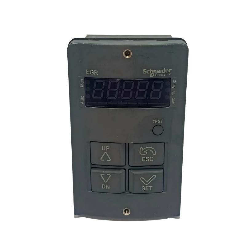
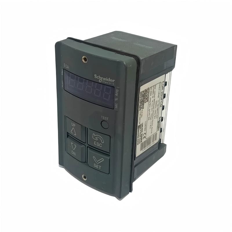
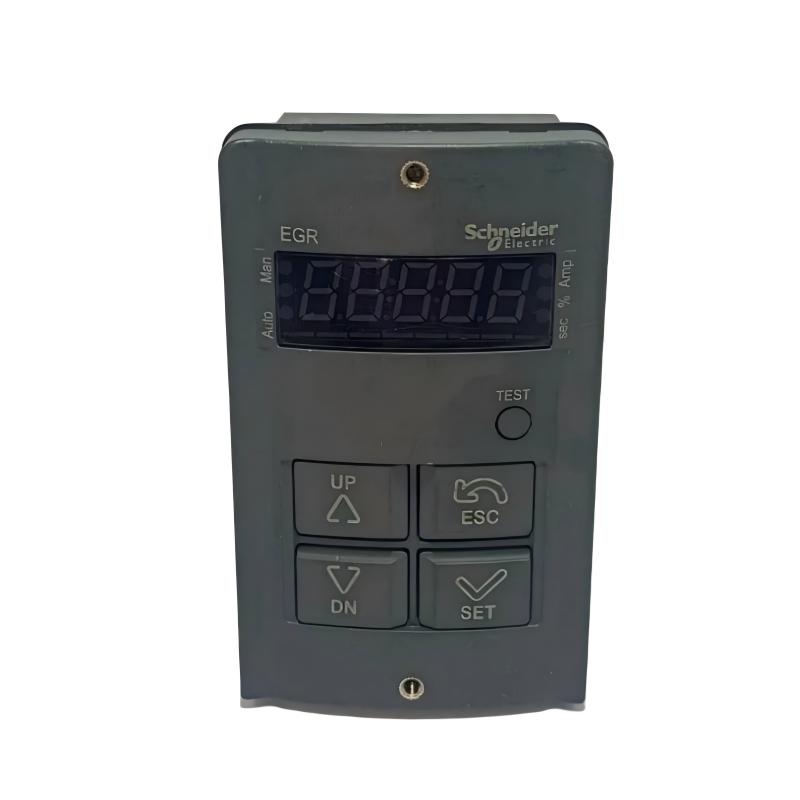
The Schneider Electric EGR-20UFCM Protective Relay is a digital earth leakage and ground fault protection relay designed to monitor residual current in low-voltage electrical systems. It helps detect abnormal current leakage to ground and provides a protective output when the measured current exceeds the configured threshold for the selected operating time.
The EGR-20UFCM is intended for applications where electrical leakage monitoring is important for equipment protection, electrical system reliability, and operational safety. It can be used in motor control panels, industrial distribution boards, and other low-voltage installations that require ground fault detection.
Unlike a conventional electromechanical relay that simply changes contact state, the EGR-20UFCM provides digital measurement and configurable protection settings. Its display allows technicians to view measured leakage current and programmed values. The relay also supports fault-history storage, helping maintenance personnel review recent protection events.
A key feature of this model is its compatibility with both current-output and voltage-output zero-phase current transformers (ZCTs). This allows the relay to work with different residual-current sensing arrangements, provided the selected transformer matches the relay input requirements.
The EGR-20UFCM also supports Modbus RTU communication. This function allows relevant operating information to be integrated into a compatible monitoring or supervisory system, depending on the communication configuration.
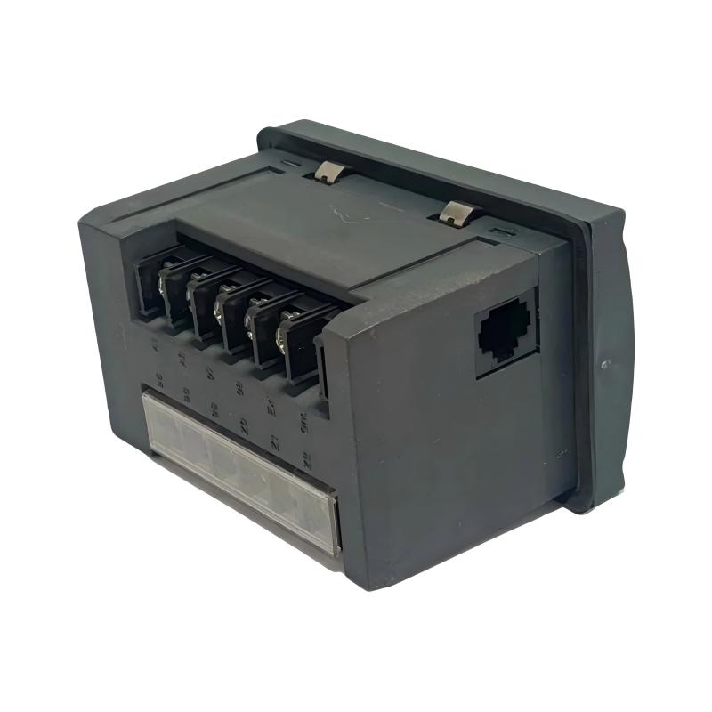
The model is a flush-panel-mounted version. Its full catalog number should be checked when selecting a replacement because related EGR models may use socket mounting or different ZCT input configurations.
Technical Specifications
| Parameter | Specification |
|---|---|
| Brand / Product Range | Schneider Electric EGR |
| Model | EGR-20UFCM |
| Product Type | Digital Earth Leakage / Ground Fault Protection Relay |
| Mounting Type | Flush Panel Mount |
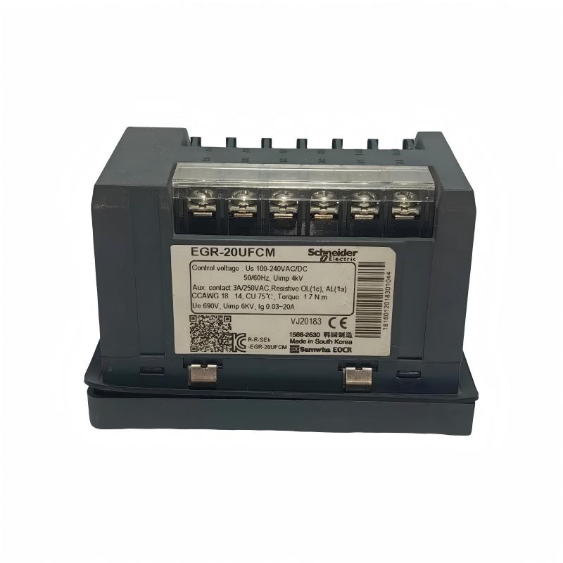
| Detection Range | 0.03–20 A (current-input configuration) |
| Voltage-Input Detection Range | 0.1–10 A |
| ZCT Compatibility | 200 mA / 1.5 mA or 200 mA / 100 mV |
| Operating Voltage | 100–240 V AC/DC |
| Operating Voltage Range | 85–264 V AC/DC |
| Supply Frequency | 50/60 Hz |
| Output Contact | 1 SPDT (1C) |
| Output Contact Rating | 3 A at 250 V AC, resistive load |
| Ground Fault Operating Time | 0.03 s, 0.05 s, 0.1–10 s |
| Ground Fault Delay Setting | 0–30 s |
| Communication | Modbus RTU |
| Display | Digital LED display |
| Fault History | Stores up to five operation records |
| Reset Method | Manual or automatic |
| Noise Filtering | Built-in noise-filter function |
| Protection Rating | IP52 when protective cover is installed |
| Operating Temperature | -20 to +60°C |
| Storage Temperature | -40 to +80°C |
| Mounting | Flush panel mounting |
| Dimensions Provided | 52 × 70 × 71 mm |
| Weight Provided | 0.245 kg |
Note: Specifications should be checked against the exact product revision and installation documentation. The dimensions and weight shown above are the supplied listing values; the manufacturer’s dimensional drawing should be consulted before panel cutout design.
Function and Working Principle
The EGR-20UFCM monitors residual current through an external zero-phase current transformer. Under normal operating conditions, the vector sum of the currents passing through the monitored conductors should be approximately zero. When an insulation fault or unintended current path develops, an imbalance may occur.
The ZCT detects this imbalance and sends a corresponding signal to the relay. The EGR-20UFCM processes the signal, compares the measured value with the configured protection threshold, and determines whether the output relay should operate.
1. Earth Leakage Current Detection
The relay is designed to measure leakage or ground fault current using a compatible ZCT.
For the current-input arrangement, the documented detection range is 0.03–20 A. The voltage-input arrangement supports a different detection range and uses a compatible voltage-output ZCT.
The correct input type must be selected in accordance with the installed transformer. An incorrect ZCT type or wiring arrangement can cause inaccurate measurement or prevent proper protection operation.
2. Adjustable Protection Threshold
The EGR-20UFCM allows the ground fault current threshold to be configured according to the application.
The selected threshold determines the current level at which the relay is expected to initiate its protection response. The setting must be coordinated with the electrical installation, connected equipment, expected leakage current, and applicable protection requirements.
A threshold that is too low may result in unwanted trips, while a threshold that is too high may reduce the effectiveness of the intended protection.
3. Adjustable Operating Time
The relay provides configurable ground fault operating-time settings. This allows engineers to coordinate the protection response with the characteristics of the electrical system.
The documented operating-time settings include 0.03 seconds, 0.05 seconds, and an adjustable range from 0.1 to 10 seconds. A separate ground fault delay setting is available from 0 to 30 seconds.
These settings should be selected by qualified personnel after considering the protection objective and coordination with upstream and downstream devices.
4. Digital Display and Parameter Configuration
The built-in LED display provides access to measurement values and configuration settings.
The front-panel controls allow technicians to navigate through available parameters, change values, and save the selected settings. This simplifies commissioning and routine adjustment without requiring a separate programming device for basic configuration.
5. Fault History Recording
The EGR-20UFCM can store up to five recent operation records. This information can help maintenance personnel review previous protection events and investigate possible causes.
Fault history is useful for troubleshooting recurring leakage conditions, insulation deterioration, wiring problems, or abnormal electrical disturbances. It should be considered a diagnostic aid rather than a substitute for a complete fault investigation.
6. Noise Filtering
Industrial electrical environments may contain electrical noise and harmonics produced by variable frequency drives, UPS equipment, and power converters.
The EGR-20UFCM includes a noise-filter function designed to help improve detection stability in electrically noisy environments. Correct installation, ZCT selection, grounding practices, and cable routing remain necessary for reliable measurement.
Role in Industrial Control Systems
The EGR-20UFCM can serve as a ground fault monitoring and protection component within a low-voltage electrical control system.
It is commonly installed in a control or distribution panel, where it receives a sensing signal from a ZCT and provides an output contact to the associated protection or control circuit.
Motor Protection Systems
In motor installations, insulation deterioration or cable damage can create leakage-current conditions. A ground fault relay can monitor the relevant electrical circuit and provide a protective signal when its configured operating conditions are met.
The EGR-20UFCM can be incorporated into motor protection arrangements when its sensing method, settings, and output interface are appropriate for the application.
Circuit Breaker and Contactor Coordination
The relay’s SPDT output contact can be used in a suitable control circuit to initiate an alarm, operate a trip circuit, or provide a signal to another control device.
The exact wiring depends on the system design. The relay should not be assumed to interrupt the main power circuit directly; its output is a control contact that must be coordinated with the appropriate switching and protective equipment.
PLC and Supervisory Monitoring
The Modbus RTU communication function allows the relay to be incorporated into a compatible monitoring system.
A PLC or supervisory control system may use available communication information to support centralized monitoring and maintenance. Communication wiring, addressing, serial settings, and supported data points must be confirmed from the applicable documentation.
Electrical Distribution Monitoring
The relay can be installed in low-voltage distribution panels where leakage-current monitoring is required. It can provide an additional layer of monitoring alongside circuit breakers, contactors, and other electrical protection devices.
The protection arrangement must be engineered as a complete system. The EGR-20UFCM does not replace all forms of overcurrent, short-circuit, or personnel protection.
Industrial Applications
1. Industrial Motor Control Panels
Motor control centers often contain motors, contactors, overload protection, and associated control equipment. The EGR-20UFCM can be used in an appropriate ground fault monitoring arrangement to detect residual current conditions.
This is particularly relevant where motor insulation condition and electrical reliability are important maintenance considerations.
2. Low-Voltage Distribution Boards
In industrial distribution boards, ground fault monitoring can help identify abnormal leakage conditions in connected circuits.
The relay’s configurable current and time settings allow the protection arrangement to be adapted to the electrical system, subject to correct engineering and coordination.
3. Pumping and Water Treatment Systems
Pumping installations may operate continuously or in environments where electrical equipment is exposed to demanding operating conditions.
A compatible ground fault protection relay can provide additional monitoring for pump motors and related electrical circuits. Installation must account for the electrical enclosure, grounding arrangement, ZCT placement, and environmental conditions.
4. Manufacturing Facilities
Production equipment may contain motors, drives, power converters, and other electrical loads. Leakage-current monitoring can support maintenance programs by helping identify abnormal electrical conditions.
The EGR-20UFCM’s noise-filter function is relevant to installations where electrical interference from power-electronic equipment needs to be considered.
5. HVAC and Auxiliary Equipment
Fans, pumps, and other auxiliary motors in HVAC systems may be included in ground fault monitoring arrangements.
The relay can be used where its current range, sensing configuration, and control output are compatible with the equipment and electrical design.
6. Industrial Electrical Maintenance
The digital display and stored operation history can help technicians investigate ground fault events. By reviewing measured values and recent trips, maintenance teams can narrow down potential issues and plan further inspection.
The relay should be tested periodically in accordance with the applicable maintenance procedure.
Installation and System Integration
Correct installation is essential for accurate residual-current measurement and dependable protection operation.
1. Select the Correct ZCT
The EGR-20UFCM supports current-output and voltage-output ZCT configurations.
The documented ZCT ratings include:
- Current output: 200 mA / 1.5 mA.
- Voltage output: 200 mA / 100 mV.
The relay input configuration must match the connected ZCT. Do not connect an incompatible transformer simply because its physical dimensions or appearance are similar.
2. Install the ZCT Correctly
The monitored conductors must pass through the ZCT according to the wiring arrangement specified for the electrical system.
For a typical three-phase circuit, the relevant live conductors must be routed through the same sensing transformer as required by the design. Incorrect conductor routing can result in measurement errors or failure to detect the intended residual current.
The ZCT secondary circuit should not be grounded unless the manufacturer’s instructions explicitly require otherwise. Shielded cable is recommended for the secondary signal wiring where appropriate.
3. Connect the Relay Power Supply
The documented operating supply is 100–240 V AC/DC, with an operating range of 85–264 V AC/DC.
Confirm the control supply voltage and polarity requirements before connecting the relay. The manufacturer’s wiring guidance recommends using an isolated control power supply.
4. Connect the Output Contact
The relay provides one SPDT output contact, with a documented rating of 3 A at 250 V AC for a resistive load.
The output can be incorporated into a suitable alarm, contactor, or circuit-breaker trip control circuit. Verify the connected load and switching requirements before using the contact.
5. Configure Protection Parameters
After installation, configure the ZCT input type, ground fault current threshold, operating time, delay time, reset method, and other relevant parameters.
The settings must be based on the system’s electrical characteristics and protection requirements. Avoid copying parameter values from another installation without checking whether they are suitable for the present application.
6. Configure Modbus RTU Communication
When remote monitoring is required, configure the communication parameters according to the system design and the relay documentation.
Check the serial wiring, communication address, baud rate, parity, and supported data points. Use suitable communication cable and avoid routing communication wiring alongside high-interference power conductors where possible.
7. Perform Functional Testing
After installation, carry out the manufacturer’s recommended functional checks. Verify that the relay receives the correct ZCT signal, displays plausible measurement values, and operates its output contact under the specified test conditions.
Confirm that the connected trip or alarm circuit responds correctly. Record the final settings and test results for future maintenance.
Compatible System Components
The EGR-20UFCM operates as part of a wider electrical protection arrangement. The following components may be used with it, subject to the exact installation design.
| Component | Function | Compatibility Considerations |
|---|---|---|
| Zero-phase current transformer (ZCT) | Detects residual current in the monitored circuit | Must match the relay’s current or voltage input specification |
| Molded case circuit breaker (MCCB) | Provides circuit isolation and overcurrent protection | Trip circuit must be designed for the relay output |
| Magnetic contactor | Switches the motor or electrical load | Coil voltage and control wiring must match the system |
| PLC | Coordinates alarms and control actions | Confirm Modbus RTU settings and supported data points |
| HMI | Displays electrical status and alarms | Usually connected through a PLC or compatible communication system |
| Isolated control power supply | Supplies the relay control circuit | Must meet the specified voltage requirements |
| RS-485 communication cable | Supports Modbus RTU communication | Use appropriate cable and correct polarity |
| Control cabinet | Houses the relay and associated equipment | Panel cutout, mounting depth, and environmental conditions must be checked |
These are examples of system components, not a statement that they are supplied with the relay.
Alternative Models and Replacement Considerations
The EGR product family includes models with different current ranges, mounting arrangements, and ZCT input types. Replacement selection must be based on the complete model designation.
| Model | General Configuration | Replacement Considerations |
|---|---|---|
| EGR-20UFCM | 0.03–20 A, flush panel mount, current/voltage ZCT input, Modbus RTU | Reference model |
| EGR-20USAM | 0.03–20 A, socket mounting, current-input ZCT configuration, Modbus RTU | Different mounting and sensing configuration |
| EGR-10USVM | 0.1–10 A, socket mounting, voltage-input ZCT configuration, Modbus RTU | Different detection range and input type |
A replacement should be checked against:
- Detection current range.
- ZCT output type and rated secondary signal.
- Operating supply voltage.
- Output contact arrangement and rating.
- Ground fault operating-time settings.
- Delay-time requirements.
- Mounting style and panel cutout.
- Communication requirements.
- Wiring and terminal assignments.
A related model from the same product family should not be treated as a direct replacement without checking these details.
Key Advantages
Wide Ground Fault Detection Range
The EGR-20UFCM provides a current-input detection range of 0.03–20 A, supporting a range of industrial leakage-monitoring requirements.
Dual ZCT Input Compatibility
Its compatibility with current-output and voltage-output ZCT configurations offers flexibility when designing or maintaining ground fault monitoring systems.
Digital Measurement Display
The LED display provides access to measured leakage current and configured protection values, helping technicians review relay operation.
Adjustable Protection Timing
Configurable operating and delay times allow the relay to be coordinated with the requirements of the electrical installation.
Modbus RTU Communication
The communication function supports integration with compatible PLC and supervisory monitoring systems.
Fault History Storage
The relay can retain up to five recent operation records, providing useful information for troubleshooting and maintenance.
Noise-Filter Function
The built-in filtering function is designed to improve measurement stability in electrical environments containing interference from power converters and similar equipment.
Flexible Reset Options
Manual and automatic reset methods allow the relay’s recovery behavior to be configured according to the protection design.
Technical FAQs
1. What is the Schneider Electric EGR-20UFCM?
The EGR-20UFCM is a digital earth leakage and ground fault protection relay. It monitors residual current through an external ZCT and operates its output contact when configured protection conditions are met.
2. What is the current detection range?
The current-input configuration has a documented detection range of 0.03–20 A. The voltage-input configuration supports a different range of 0.1–10 A.
3. What power supply does the EGR-20UFCM require?
Its rated operating supply is 100–240 V AC/DC, with a documented operating range of 85–264 V AC/DC.
4. Does the relay support Modbus communication?
Yes. The EGR-20UFCM supports Modbus RTU communication, allowing integration with compatible monitoring and automation systems.
5. What type of ZCT can be used?
The relay supports current-output ZCTs rated 200 mA / 1.5 mA and voltage-output ZCTs rated 200 mA / 100 mV. The relay’s selected input type must match the installed transformer.
6. How many output contacts does it provide?
The relay has one SPDT (1C) output contact, rated at 3 A / 250 V AC for a resistive load.
7. Can it be used for motor protection?
It can be incorporated into a motor ground fault protection arrangement when the ZCT, current threshold, timing, output circuit, and protection coordination are correctly selected.
8. Does the relay store fault records?
Yes. It can store up to five recent operation records, which can assist maintenance personnel when investigating recurring ground fault events.
9. What is the mounting type?
The EGR-20UFCM is a flush-panel-mounted model. It should not be confused with related socket-mounted EGR models.
10. Can it replace an EGR-20USAM?
Not automatically. Although both models have a 0.03–20 A current range, their mounting and ZCT input configurations differ. Verify the sensing method, terminal arrangement, and panel installation requirements before replacement.
Procurement and Maintenance Recommendations
When purchasing the EGR-20UFCM, verify the complete model designation and confirm that the unit is the flush-panel-mounted version. Check the ZCT input requirements, operating supply, output contact rating, and communication needs against the existing installation.
For replacement projects, inspect the original wiring diagram and record the relay’s parameter settings before removing the existing unit. Confirm that the new relay is compatible with the installed ZCT and that the panel cutout and mounting depth are suitable.
For used or surplus equipment, request clear photographs of the front display, terminals, model label, and housing. Ask about the unit’s condition and whether it has been functionally tested. Confirm the included accessories and warranty terms before placing an order.
During routine maintenance, inspect terminal connections, ZCT wiring, control power, and communication wiring. Check that the relay’s displayed measurements are plausible and perform the recommended functional test at the maintenance interval specified by the installation procedure.
If repeated ground fault trips occur, investigate the electrical circuit, motor insulation, cables, moisture exposure, and connected equipment. Do not simply increase the trip threshold or delay time without identifying the cause and confirming that the revised settings remain appropriate for the protection design.
Conclusion
The Schneider Electric EGR-20UFCM Protective Relay is a digital earth leakage and ground fault protection device designed for low-voltage industrial electrical systems. It provides configurable residual-current monitoring, adjustable operating and delay times, a digital display, fault-history storage, noise filtering, and Modbus RTU communication.
Its compatibility with current-output and voltage-output ZCTs makes it suitable for different ground fault sensing arrangements when correctly configured. For installation and replacement projects, the most important considerations are ZCT compatibility, protection settings, output contact wiring, communication requirements, and flush-panel mounting dimensions.
Accurate model identification and correct system integration help ensure that the EGR-20UFCM performs its intended monitoring and protection role in industrial electrical installations.